1
V76MSE.book Page 1 Wednesday, May 19, 1999 1:25 PM
User’s Guide
V76MSE.book Page 2 Wednesday, May 19, 1999 1:25 PM
'(((!
%
%)*+,
% #-(........
&/#"
'(((
!
%)*+,
" #$$$$$$$$$$$$$$$$$$$$$$$$$$$$$$$$$
#$$$$$$$$$$$$$$$$$$$$$$$$$$$$$$$$$
%&
#$$$$$$$$$$$$$$$$$$$$$$$$$$$$$$$$$
%%
#$$$$$$$$$$$$$$$$$$$$$$$$$$$$$$$$$
0
V76MSE.book Page iii Wednesday, May 19, 1999 1:25 PM
iii
Notices. . . . . . . . . . . . . . . . . . . . . . . . . . . . . . . . . . . . . . . . . . . . . . . . . v
Chapter 1 Getting Started . . . . . . . . . . . . . . . . . . . . . . . . . . . . . . 1
Overview . . . . . . . . . . . . . . . . . . . . . . . . . . . . . . . . . . . . . . . . . . . . . . . . . . 3
Preinstallation . . . . . . . . . . . . . . . . . . . . . . . . . . . . . . . . . . . . . . . . . . . . . . 4
Selecting a Site . . . . . . . . . . . . . . . . . . . . . . . . . . . . . . . . . . . . . . . . . . 4
Unpacking Components. . . . . . . . . . . . . . . . . . . . . . . . . . . . . . . . . . . . 4
Features . . . . . . . . . . . . . . . . . . . . . . . . . . . . . . . . . . . . . . . . . . . . . . . . . . . 5
Front Panel. . . . . . . . . . . . . . . . . . . . . . . . . . . . . . . . . . . . . . . . . . . . . . 5
Rear Panel . . . . . . . . . . . . . . . . . . . . . . . . . . . . . . . . . . . . . . . . . . . . . . 6
Connecting System Components . . . . . . . . . . . . . . . . . . . . . . . . . . . . . . . . 8
Connecting the Keyboard. . . . . . . . . . . . . . . . . . . . . . . . . . . . . . . . . . . 8
Connecting the Monitor . . . . . . . . . . . . . . . . . . . . . . . . . . . . . . . . . . . . 9
Connecting the Mouse . . . . . . . . . . . . . . . . . . . . . . . . . . . . . . . . . . . . . 9
Connecting the Printer (optional). . . . . . . . . . . . . . . . . . . . . . . . . . . . 10
Connecting Multimedia Components . . . . . . . . . . . . . . . . . . . . . . . . . 10
Connecting to the Network (optional) . . . . . . . . . . . . . . . . . . . . . . . . 11
Connecting the Fax/Modem (optional) . . . . . . . . . . . . . . . . . . . . . . . . 11
Connecting USB Devices (optional) . . . . . . . . . . . . . . . . . . . . . . . . . . 12
Turning On Your Computer . . . . . . . . . . . . . . . . . . . . . . . . . . . . . . . . . . . 13
Turning Off Your Computer . . . . . . . . . . . . . . . . . . . . . . . . . . . . . . . . . . . 14
Troubleshooting . . . . . . . . . . . . . . . . . . . . . . . . . . . . . . . . . . . . . . . . . . . . 15
Error Messages . . . . . . . . . . . . . . . . . . . . . . . . . . . . . . . . . . . . . . . . . . . . 17
Software Error Messages. . . . . . . . . . . . . . . . . . . . . . . . . . . . . . . . . . 17
System Error Messages. . . . . . . . . . . . . . . . . . . . . . . . . . . . . . . . . . . 17
Correcting Error Conditions . . . . . . . . . . . . . . . . . . . . . . . . . . . . . . . . 19
Chapter 2 System Board Information. . . . . . . . . . . . . . . . . . . . . . 21
Features . . . . . . . . . . . . . . . . . . . . . . . . . . . . . . . . . . . . . . . . . . . . . . . . . . 23
Board Layout . . . . . . . . . . . . . . . . . . . . . . . . . . . . . . . . . . . . . . . . . . . . . . 25
Jumpers and Connectors . . . . . . . . . . . . . . . . . . . . . . . . . . . . . . . . . . . . . 28
Floppy Disk / Hard Disk Support . . . . . . . . . . . . . . . . . . . . . . . . . . . . . . . 31
Video Function . . . . . . . . . . . . . . . . . . . . . . . . . . . . . . . . . . . . . . . . . . . . . 32
Audio Function . . . . . . . . . . . . . . . . . . . . . . . . . . . . . . . . . . . . . . . . . . . . . 33
USB Support . . . . . . . . . . . . . . . . . . . . . . . . . . . . . . . . . . . . . . . . . . . . . . 34
Hardware Monitoring Function. . . . . . . . . . . . . . . . . . . . . . . . . . . . . . . . . 35
Modem Ring-in Function . . . . . . . . . . . . . . . . . . . . . . . . . . . . . . . . . . . . . 36
Wake-on LAN . . . . . . . . . . . . . . . . . . . . . . . . . . . . . . . . . . . . . . . . . . . . . . 37
V76MSE.book Page iv Wednesday, May 19, 1999 1:25 PM
iv
Table of Contents
Chapter 3 `BIOS Information . . . . . . . . . . . . . . . . . . . . . . . . . . . 39
Entering Setup . . . . . . . . . . . . . . . . . . . . . . . . . . . . . . . . . . . . . . . . . . . . . 42
System Information . . . . . . . . . . . . . . . . . . . . . . . . . . . . . . . . . . . . . . . . . 44
Product Information . . . . . . . . . . . . . . . . . . . . . . . . . . . . . . . . . . . . . . . . . 48
Disk Drives . . . . . . . . . . . . . . . . . . . . . . . . . . . . . . . . . . . . . . . . . . . . . . . . 50
Onboard Peripherals. . . . . . . . . . . . . . . . . . . . . . . . . . . . . . . . . . . . . . . . . 54
Onboard Device Settings . . . . . . . . . . . . . . . . . . . . . . . . . . . . . . . . . . 56
Power Management . . . . . . . . . . . . . . . . . . . . . . . . . . . . . . . . . . . . . . . . . 58
Boot Options . . . . . . . . . . . . . . . . . . . . . . . . . . . . . . . . . . . . . . . . . . . . . . 60
Date and Time . . . . . . . . . . . . . . . . . . . . . . . . . . . . . . . . . . . . . . . . . . . . . 63
System Security . . . . . . . . . . . . . . . . . . . . . . . . . . . . . . . . . . . . . . . . . . . 64
Setting a Password . . . . . . . . . . . . . . . . . . . . . . . . . . . . . . . . . . . . . . 66
Changing or Removing the Password . . . . . . . . . . . . . . . . . . . . . . . . 67
Bypassing the Password . . . . . . . . . . . . . . . . . . . . . . . . . . . . . . . . . . 68
Advanced Options . . . . . . . . . . . . . . . . . . . . . . . . . . . . . . . . . . . . . . . . . . 69
Memory/Cache Options . . . . . . . . . . . . . . . . . . . . . . . . . . . . . . . . . . . 70
PnP/PCI Options . . . . . . . . . . . . . . . . . . . . . . . . . . . . . . . . . . . . . . . . 72
Load Default Settings . . . . . . . . . . . . . . . . . . . . . . . . . . . . . . . . . . . . . . . . 74
Abort Settings Change . . . . . . . . . . . . . . . . . . . . . . . . . . . . . . . . . . . . . . . 75
Exiting Setup . . . . . . . . . . . . . . . . . . . . . . . . . . . . . . . . . . . . . . . . . . . . . . 76
Chapter 4 Upgrading the System . . . . . . . . . . . . . . . . . . . . . . . . 77
Installation Precautions . . . . . . . . . . . . . . . . . . . . . . . . . . . . . . . . . . . . . . 79
ESD Precautions . . . . . . . . . . . . . . . . . . . . . . . . . . . . . . . . . . . . . . . . 79
Preinstallation Instructions . . . . . . . . . . . . . . . . . . . . . . . . . . . . . . . . 79
Post-installation Instructions . . . . . . . . . . . . . . . . . . . . . . . . . . . . . . . 80
Opening the System . . . . . . . . . . . . . . . . . . . . . . . . . . . . . . . . . . . . . . . . . 81
Removing the Housing Cover . . . . . . . . . . . . . . . . . . . . . . . . . . . . . . 81
Replacing the Housing Cover. . . . . . . . . . . . . . . . . . . . . . . . . . . . . . . 82
Installing Additional Memory . . . . . . . . . . . . . . . . . . . . . . . . . . . . . . . . . . 84
Installing a DIMM . . . . . . . . . . . . . . . . . . . . . . . . . . . . . . . . . . . . . . . 86
Removing a DIMM. . . . . . . . . . . . . . . . . . . . . . . . . . . . . . . . . . . . . . . 87
Reconfiguring the System . . . . . . . . . . . . . . . . . . . . . . . . . . . . . . . . . 87
Upgrading the CPU. . . . . . . . . . . . . . . . . . . . . . . . . . . . . . . . . . . . . . . . . . 88
Removing the CPU. . . . . . . . . . . . . . . . . . . . . . . . . . . . . . . . . . . . . . . 88
Installing the Upgrade CPU . . . . . . . . . . . . . . . . . . . . . . . . . . . . . . . . 90
Replacing the Hard Disk . . . . . . . . . . . . . . . . . . . . . . . . . . . . . . . . . . . . . . 92
Installing and Removing a PCI Card . . . . . . . . . . . . . . . . . . . . . . . . . . . . . 95
Installing a PCI Card . . . . . . . . . . . . . . . . . . . . . . . . . . . . . . . . . . . . . 95
Removing a PCI Card. . . . . . . . . . . . . . . . . . . . . . . . . . . . . . . . . . . . . 95
Index . . . . . . . . . . . . . . . . . . . . . . . . . . . . . . . . . . . . . . . . . . . . . . . . . . 97
V76MSE.book Page v Wednesday, May 19, 1999 1:25 PM
v
FCC Notice
1
%'23
4
5
!
#
❑
❑
!
❑
❑
0
Notice: Shield Cables
3
Notice: Peripheral Devices
6
708
1
46
9
/
Caution
+
3
V76MSE.book Page vi Wednesday, May 19, 1999 1:25 PM
vi
Notices
Use Conditions
%'236:
#7'8
7;8
Notice: Canadian Users
14
!9)4
Remarque à l’intention des utilisateurs canadiens
<41
=<
Important Safety Instructions
3
*&
4*
&
&
>
9
!
&
&
!
4
V76MSE.book Page vii Wednesday, May 19, 1999 1:25 PM
vii
:
4
&
4
*
4#
?
!4
!
!
:
:
4
4
!
!
@
*
4
?A1
&
B
*
7
8!
#
*C0
%9;D';2/
/&)4"'27-E
8
V76MSE.book Page viii Wednesday, May 19, 1999 1:25 PM
viii
Notices
Year 2000 Compliance Statement
F;GGG9H C5
F;GGGI
+ C C+F"B;GGG
;GGG
3F;GGG#00
00
;0
Laser Compliance Statement
C'C)%6&*
! /!!1C)C)&!!6 ?5) 6%) /6!&).%6*)61)"
%%)!CC)&)C)'%6&*!
&!!6 &*3!)*C)
! /!!1C)) &+6*/)*))/!)6*)
).%6!!6 *.F6 C*6B 'C)C!)C)BC)'
* !51)C)5C* ,?)
1&)B* ,,)J33 ) !5&)"5CC*)K)
%6&*6CL)&)CC)!
&!!M CL)! /!!1C)C)
1!)6)/!)).%6 ))C6F6
C)NC! ,/)&N1 ! ,)!BB)! &!
NC) V76MSE.book Page ix Wednesday, May 19, 1999 1:25 PM
ix
/6AC/)6C)C! C)N)!CFCC)
C)NC ! , N&)
&)CNJ%% &
NCN*!O6N)))) !)O! !NC)
C)NC ! , &)
J%% &!)O! !NC)
&)CN
C)NC! , &)B)CN% )!!BB)
!
!NC)
Lithium Battery Statement
&
4
&
+
C9):P*P
C<
Q
):1
1
:
)
R
B
R
%SS:SSS:/
:
5SSS
::
)ST1)U
5S
)15
V76MSE.book Page x Wednesday, May 19, 1999 1:25 PM
x
Notices
V76MSE.book Page 1 Wednesday, May 19, 1999 1:25 PM
Chapter 1
V76MSE.book Page 2 Wednesday, May 19, 1999 1:25 PM
V76MSE.book Page 3 Wednesday, May 19, 1999 1:25 PM
3
Overview
!"#$%
&$&
'!&!& (!
(!$)$
%*$%
&+&+
**!"+,-%*
%.").")*
*/*/*
(+
&&
&$&
%
%% (!*
*00++
-
%-$%"
$*-/ 1*$*.")*
$*
,
2*%%
""34*"+
,*".1&4*56751$%
V76MSE.book Page 4 Wednesday, May 19, 1999 1:25 PM
4
Chapter 1
Getting Started
Preinstallation
$8
❑
"$
❑
.-$
Selecting a Site
$$%8
❑
%%
9$$
9%**
%*$$9
❑
%9
❑
%0%
Unpacking Components
.-0%"-$
%%
-$%
%%$$$
V76MSE.book Page 5 Wednesday, May 19, 1999 1:25 PM
5
Features
$%*-%*
*%-*-
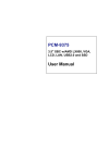
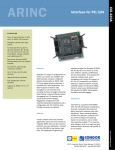
Front Panel
$%
No.
Component
1
Headphone/Earphone port
2
CD-ROM tray
3
Stop/Eject button
4
Skip/Forward button
5
CD-ROM LED
V76MSE.book Page 6 Wednesday, May 19, 1999 1:25 PM
6
Chapter 1
Getting Started
No.
Component
6
Increase Volume button
7
Decrease Volume button
8
Turbo LED
9
Power LED
10
Hard disk drive LED
11
Power button
12
3.5-inch floppy disk drive eject button
13
3.5-inch floppy disk drive
14
3.5-inch floppy disk drive LED
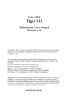
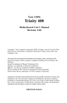
Rear Panel
$%
V76MSE.book Page 7 Wednesday, May 19, 1999 1:25 PM
7
No.
Component
1
Fan
2
System main power switch
3
Voltage selector
4
System power socket
5
USB ports
6
PS/2 mouse port
7
PS/2 keyboard port
8
Serial port 2
9
Parallel port
10
VGA/Monitor port
11
Speaker-out/Line-out port
12
Line-in port
13
Game/MIDI portt
14
Microphone-in port
15
Add-on card brackets
V76MSE.book Page 8 Wednesday, May 19, 1999 1:25 PM
8
Chapter 1
Getting Started
Connecting System Components
Caution: Do not turn on the system main power switch on the rear panel of
the system or plug the system in until you finish connecting all system
components.
$
%8
Connecting the Keyboard
!$-%-%-
V76MSE.book Page 9 Wednesday, May 19, 1999 1:25 PM
9
Connecting the Monitor
!$$:( Connecting the Mouse
!$
V76MSE.book Page 10 Wednesday, May 19, 1999 1:25 PM
10
Chapter 1
Getting Started
Connecting the Printer (optional)
-%%%%&%
*
&%*
;"<!=$3
Connecting Multimedia Components
>%
8
V76MSE.book Page 11 Wednesday, May 19, 1999 1:25 PM
11
Connecting to the Network (optional)
>%%/ 1/ 1-
-%%-*$
--
Connecting the Fax/Modem (optional)
>%%0+*
0+
8
V76MSE.book Page 12 Wednesday, May 19, 1999 1:25 PM
12
Chapter 1
Getting Started
Connecting USB Devices (optional)
.")%
$%%
.")*%$.")
Note: Most USB devices have a built-in USB port which allows you to
daisy-chain other devices.
V76MSE.book Page 13 Wednesday, May 19, 1999 1:25 PM
13
Turning On Your Computer
%*
%8
%
**0*-*
/%-%
!%
5%$*%
V76MSE.book Page 14 Wednesday, May 19, 1999 1:25 PM
14
Chapter 1
Getting Started
Turning Off Your Computer
%
**0*-*
!%
?-%$
%"%
Note: You do not need to turn off the system main power switch on the rear
panel every time you turn off your computer.
Turn off the system main power switch only:
- if you will not use your system for a long period of time.
- if you need to open your system for any purpose, such as troubleshooting
or upgrading.
If the system main power switch is not available, you must unplug the
system.
V76MSE.book Page 15 Wednesday, May 19, 1999 1:25 PM
15
Troubleshooting
&%*%
$$$$8
General failure
❑
%$$@
❑
%@
❑
&%@
❑
&@>%-%
$$$$9
❑
%$@ %%@
#%$
Front panel light doesn’t work
❑
$*-%
-/#/#
-$%$$<A
=$,7%/#
“Garbage” or nothing appears on the screen
❑
&@&$B
%@
Warning! Never open the monitor case. The CRT monitor retains very high
voltage levels even after the power is turned off. Refer all monitor service to
qualified service technicians.
Keyboard is dead
❑
&-%$$@%$
-%
Caution: Do not plug or unplug the keyboard while the power is on.
Printer doesn’t work
❑
&@
V76MSE.book Page 16 Wednesday, May 19, 1999 1:25 PM
16
Chapter 1
Getting Started
❑
&
@
❑
%$
$@)%
2*-
%
❑
&B@-
$
❑
$@$*
%0$
Add-on card fails intermittently
❑
$@<!!+!&
=$C,%
".% "<#$"=
$D,$ /
)&".%
If you receive an error message
❑
<#
$=$
;C
V76MSE.book Page 17 Wednesday, May 19, 1999 1:25 PM
17
Error Messages
&%$*$
1$-
%%
$$$
$%$8
❑
"
❑
"%
Software Error Messages
"$%%$%
$%%%
$%%%&%
%$*%$%
System Error Messages
%$
$%$*
$%
%$
Error Message
Corrective Action
Memory Error at
MMMM:SSSS:OOOOh
(R:xxxxh, W:xxxxh)
Replace the DIMMs.
System Management Memory
Bad
Replace the DIMMs.
Keyboard Interface Error
Check the keyboard interface circuit or
change the keyboard.
Keyboard Error or Keyboard
Not Connected
Reconnect or replace the keyboard.
V76MSE.book Page 18 Wednesday, May 19, 1999 1:25 PM
18
Chapter 1
Getting Started
Error Message
Corrective Action
Pointing Device Error
Reconnect or replace the pointing
device.
Pointing Device Interface Error
Check the pointing device interface
circuit.
Pointing Device IRQ Conflict
Enter Setup and change the IRQ setting
of the PS/2 mouse.
IDE Drive 0 Error
IDE Drive 1 Error
IDE Drive 2 Error
IDE Drive 3 Error
Replace the disk drive or the HDD
(hard disk drive) controller. Check the
HDD cable connections and IDE
settings in Setup.
IDE Drive 0 / 1 / 2 / 3 Auto
Detection Failed
Replace the disk drive or the hard disk
drive controller. Check the HDD cable
connections and IDE settings in Setup.
Floppy Drive A Error
Floppy Drive B Error
Check if there is no floppy disk in the
drive. If there is, turn off the system
and check the cable connections. If the
connections are okay and the error
message continues to show, replace
the floppy drive.
Floppy Disk Controller Error
Check the floppy drive cable and its
connections. If the cable is good and
properly connected, the floppy disk
controller may be the problem.
Change the floppy disk controller or
disable the onboard controller by
installing another add-on card with a
controller.
CPU Clock Mismatch
When the user changes the CPU
frequency, this message will be shown
once. Then the BIOS will adjust the
CPU clock automatically.
Serial Port Conflict
Change the onboard serial port
address in Setup or change the add-on
card serial port address.
V76MSE.book Page 19 Wednesday, May 19, 1999 1:25 PM
19
Error Message
Corrective Action
Parallel Port Conflict
Change the onboard parallel port
address in Setup or the parallel port
address of the add-on card.
Real-time Clock error
Check the RTC circuit or replace the
battery.
CMOS Battery Bad
Replace the onboard lithium battery.
CMOS Checksum Error
Run Setup again and reconfigure the
system.
Onboard XXX... Conflicts
Try to reassign or disable onboard
device resources.
PCI Device Error
Check the PCI card. Replace it if bad.
System Resource Conflict
Run Setup to reconfigure the system.
IRQ Setting Error
Run Setup to reconfigure the system.
Expansion ROM Address
Allocation Fail
Change the I/O expansion ROM
address.
Correcting Error Conditions
$*E!2;E$
%$% 9-%**
%
F8
">-$
%%%"*%%
%%$
"$B
$*%%
%$
%$$-%
%0%
V76MSE.book Page 20 Wednesday, May 19, 1999 1:25 PM
20
Chapter 1
Getting Started
-
%$$
&%-%
$*%%
-%%!%%-$
2&"G2
Caution: These commands are performed in DOS environment. We
recommend that you familiarize yourself with the DOS commands first
before you format your hard disk.
&%
$*%9
&%%$%
%$*%$
'
Note: If you do not know how to contact an authorized service center, call
your distributor.
V76MSE.book Page 21 Wednesday, May 19, 1999 1:25 PM
Chapter 2
V76MSE.book Page 22 Wednesday, May 19, 1999 1:25 PM
V76MSE.book Page 23 Wednesday, May 19, 1999 1:25 PM
23
Features
$%$
8
Components
❑
&;,7G)
$H33
F'
❑
%&
-
7*;3*H,*3D*;,7
)"%%
%" *$%
$,I3
)
❑
!&!&&$
#&#
❑
H" (!7
)
*1)$
❑
❑
5-/ 15/
❑
$
❑
!&&#&#
❑
#0
❑
❑
!"+,-%
❑
❑
"!!
"!!+#0!#!+#
!!#!!
❑
.").")
!&
V76MSE.book Page 24 Wednesday, May 19, 1999 1:25 PM
24
Chapter 2
System Board Information
Features
❑
!$!%
❑
-
$&
&
❑
$!& !&
)&"
❑
""567
❑
!
$
❑
.")
❑
F
$
V76MSE.book Page 25 Wednesday, May 19, 1999 1:25 PM
25
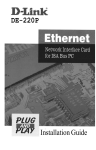
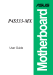
Board Layout
>%-B-$$8
$%
%8
No.
Component
1
USB ports
2
CPU temperature sensor connector
3
CPU socket
4
DIMM sockets
5
Turbo LED connector
6
Battery
7
Reset button connector
8
Power LED connector
V76MSE.book Page 26 Wednesday, May 19, 1999 1:25 PM
26
Chapter 2
System Board Information
No.
Component
9
ATX power supply connector
10
HDD LED connector
11
Floppy disk drive connector
12
IDE 1 connector
13
IDE 2 connector
14
Intrusion alarm connector
15
Super I/O controller
16
System BIOS chip
17
Power button connector
18
South bridge controller
19
Wake-on LAN connector
20
Modem ring-in connector
21
PCI slots
22
Voice modem connector
23
Audio controller
24
CD-in connector
25
Microphone-in connector
26
Line-in connector
27
Line-out connector
28
Game/MIDI port
29
VGA port
30
Parallel port
V76MSE.book Page 27 Wednesday, May 19, 1999 1:25 PM
27
No.
Component
31
COM 2 port
32
PS/2 keyboard port
33
PS/2 mouse port
34
COM 1 connector
35
Speaker connector
36
PC speaker connector
37
3-pin CPU fan connector
38
2-pin CPU fan connector
39
North bridge controller
V76MSE.book Page 28 Wednesday, May 19, 1999 1:25 PM
28
Chapter 2
System Board Information
Jumpers and Connectors
$$B
%8
$B*
$8
Jumper
Function and Settings
JP2
CPU/DRAM Frequency
1-2, 4-5
100/100 MHz
2-3, 5-6
66/100 MHz (default)
JP6
Password Check
1-2
Check password
2-3
Bypass password (default)
V76MSE.book Page 29 Wednesday, May 19, 1999 1:25 PM
29
$
8
Connector
Function
CN2
USB
CN3
Upper port: mouse; Lower port: keyboard
CN4
COM 1
CN5
Upper: parallel/printer; Lower left: COM 2; Lower
right: VGA
CN6
ATX power
CN7
Speaker
CN8
Hard disk drive (HDD) light emitting diode (LED)
CN9
PC speaker
CN10
Upper: game/MIDI; Lower left: line-out ; Lower
center: line-in, Lower right: microphone-in
CN11
IDE 2
CN12
IDE 1
CN13
Floppy disk drive (FDD)
CN17
CPU temperature sensor
CN18
Intrusion alam
CN19
Voice modem
CN20
Modem ring-in
CN21
CD-in
CN22
Wake-on LAN (WOL)
CN23
Power button
V76MSE.book Page 30 Wednesday, May 19, 1999 1:25 PM
30
Chapter 2
System Board Information
Connector
Function
CN24
Reset button
CN25
Turbo LED
DIMM 1,
DIMM 2
Memory module sockets
FN1
3-pin CPU fan
FN2
2-pin CPU fan
JP5
Power LED
V76MSE.book Page 31 Wednesday, May 19, 1999 1:25 PM
31
Floppy Disk / Hard Disk Support
!&&#
!&D.
% !&&#
%0&#-*%
&#"<A=$,7
&#
$&#-$
2$
-%
IDE Connector
Master
Slave
IDE 1 (CN12)
Hard disk 0
Hard disk 1
IDE 2 (CN11)
Hard disk 2/IDE CD-ROM
Hard disk 3
V76MSE.book Page 32 Wednesday, May 19, 1999 1:25 PM
32
Chapter 2
System Board Information
Video Function
%H (!
1$ (!
H
$*$:( 9H
V76MSE.book Page 33 Wednesday, May 19, 1999 1:25 PM
33
Audio Function
2*!&
$1;J8
❑
❑
"
❑
"
❑
(+
&&
%0
20
*<$
=$;J
V76MSE.book Page 34 Wednesday, May 19, 1999 1:25 PM
34
Chapter 2
System Board Information
USB Support
.")$$
;,
-%*
*B%-**+&"15.")*
0-%!
.")1,"<A
=$,7
V76MSE.book Page 35 Wednesday, May 19, 1999 1:25 PM
35
Hardware Monitoring Function
F
$%-%
*%-*%$
-
$ -$$"
"%
$ %$$%-$
-%&*!
"$%
F
$*% %%
F
$
V76MSE.book Page 36 Wednesday, May 19, 1999 1:25 PM
36
Chapter 2
System Board Information
Modem Ring-in Function
$%
%$0+%
% %$%
$
%%
<A=$,7
$1,J%
V76MSE.book Page 37 Wednesday, May 19, 1999 1:25 PM
37
Wake-on LAN
5-/ 15/
%%-5/
1,, 5/*-
*$*
<A=$,7
5/1,,%
V76MSE.book Page 38 Wednesday, May 19, 1999 1:25 PM
38
Chapter 2
System Board Information
V76MSE.book Page 39 Wednesday, May 19, 1999 1:25 PM
Chapter 3
V76MSE.book Page 40 Wednesday, May 19, 1999 1:25 PM
!"
V76MSE.book Page 41 Wednesday, May 19, 1999 1:25 PM
41
)&".%$$%
%)&+"%)&"
"%%%$'*
%F*%
$$<"=$*%
%
)%"*-%
%%%0"
Note: If you repeatedly receive Run Setup messages, the battery may be
bad. In this case, the system cannot retain configuration values in CMOS.
Ask a qualified technician for assistance.
V76MSE.book Page 42 Wednesday, May 19, 1999 1:25 PM
42
Chapter 3
`BIOS Information
Entering Setup
"*-%
Important! You must press Ctrl-Alt-Esc simultaneously while the system is
booting. This key combination does not work during any other time.
".%8
%)&".%8)
)&".%)/
&%$%
$%%
&%*%%-
$%%%$
/ /*
-%
V76MSE.book Page 43 Wednesday, May 19, 1999 1:25 PM
43
$".% /
8
Note: The F8 key works only when you are in the main menu. This means
that you can activate the Advanced Level only when you are in the main
menu. Also, items marked by an (*) are only visible in the Advanced Level.
%
❑
*$$%$↓
↓ ↑
↑
❑
!0$ !
$
❑
$$*←
← →
→ $
❑
!&%%
*$0"
%
%%
$%0$
$
V76MSE.book Page 44 Wednesday, May 19, 1999 1:25 PM
44
Chapter 3
`BIOS Information
System Information
$%System Information
8
$$,"%&
8
$$%%
V76MSE.book Page 45 Wednesday, May 19, 1999 1:25 PM
45
$"%
&$8
Parameter
Description
Format
Processor
Specifies the type of
processor currently installed
in your system.
Processor
Speed
Specifies the speed of the
processor currently installed
in your system.
Speed in MHz
Internal Cache
Size
Specifies the first-level or the
internal memory (i.e., the
memory integrated into the
CPU) size, and whether it is
enabled or disabled.
Cache size in KB
External Cache
Size
Specifies the second-level
cache memory size currently
supported by the system.
Cache size in KB
Floppy Drive A
Shows the floppy drive A type.
Capacity,
dimension
Floppy Drive B
Shows the floppy drive B type.
Capacity,
dimension
IDE Primary
Channel Master
Specifies the current
configuration of the IDE
device connected to the
master port of the primary IDE
channel.
Drive type,
capacity
IDE Primary
Channel Slave
Specifies the current
configuration of the IDE
device connected to the slave
port of the primary IDE
channel.
Drive type,
capacity
V76MSE.book Page 46 Wednesday, May 19, 1999 1:25 PM
46
Chapter 3
`BIOS Information
Parameter
Description
Format
IDE Secondary
Channel Master
Specifies the current
configuration of the IDE
device connected to the
master port of the secondary
IDE channel.
Drive type,
capacity
IDE Secondary
Channel Slave
Specifies the current
configuration of the IDE
device connected to the slave
port of the secondary IDE
channel.
Drive type,
capacity
Total Memory
Specifies the total amount of
onboard memory. The
memory size is automatically
detected by BIOS during the
POST. If you install additional
memory, the system
automatically adjusts this
parameter to display the new
memory size.
Memory size in
MB
1st Bank
Indicates the type of DRAM
installed in the DIMM 1
socket. The None setting
indicates that there is no
DRAM installed.
DIMM type,
capacity in MB
2nd Bank
Indicates the type of DRAM
installed in the DIMM 2
socket. The None setting
indicates that there is no
DRAM installed.
DIMM type,
capacity in MB
Serial Port 1
Shows the serial port 1
address and IRQ settings.
Address, IRQ
Serial Port 2
Shows the serial port 2
address and IRQ settings.
Address, IRQ
Parallel Port
Shows the parallel port
address and IRQ settings.
Address, IRQ
V76MSE.book Page 47 Wednesday, May 19, 1999 1:25 PM
47
Parameter
Description
Format
PS/2 Mouse
Indicates if there is a mouse
connected to your system.
This is automatically detected
by BIOS.
Displays Installed
if there is a mouse
detected;
otherwise, it
displays None.
V76MSE.book Page 48 Wednesday, May 19, 1999 1:25 PM
48
Chapter 3
`BIOS Information
Product Information
%Product Information
8
!&$
%***)&"*
%$%
9-$
$8
Parameter
Description
Product Name
Displays the model name of your system
System S/N
Displays your system’s serial number
Main Board ID
Displays the system board’s identification
number
Main Board S/N
Displays your system board’s serial number
System BIOS
Version
Specifies the version of your BIOS utility
V76MSE.book Page 49 Wednesday, May 19, 1999 1:25 PM
49
Parameter
Description
DMI BIOS version
Specifies the version of the DMI BIOS utility
installed in your system. The Desktop
Management Interface (DMI) BIOS allows you
to check your system hardware components
without actually opening your system.
Hardware checking is done via software during
start up.
V76MSE.book Page 50 Wednesday, May 19, 1999 1:25 PM
50
Chapter 3
`BIOS Information
Disk Drives
"Disk Drives$
%%
$-8
$
"$"$$$
Parameter
Description
Options
Floppy Drive A / B
Allows you to configure
your floppy drive
None
360 KB, 5.25-inch
1.2 MB, 5.25-inch
720 KB, 3.5-inch
1.44 MB, 3.5-inch
2.88 MB, 3.5-inch
LS-120 drive as
Allows you to enable the
LS-120 device installed in
your system and to specify
the function of the device.
The setting affects how
BIOS will detect the device.
Normal
Drive A
Drive B
Hard Disk
IDE Primary
Channel Master
Lets you configure the hard
disk drive connected to the
master port of IDE channel
1.
V76MSE.book Page 51 Wednesday, May 19, 1999 1:25 PM
51
Parameter
Description
IDE Primary
Channel Slave
Lets you configure the hard
disk drive connected to the
slave port of IDE channel 1.
IDE Secondary
Channel Master
Lets you configure the hard
disk drive connected to the
master port of IDE channel
2.
IDE Secondary
Channel Slave
Lets you configure the hard
disk drive connected to the
slave port of IDE channel 2.
Options
$%%&#
8
V76MSE.book Page 52 Wednesday, May 19, 1999 1:25 PM
52
Chapter 3
`BIOS Information
$
"$"$$$
Parameter
Description
Options
Type
Lets you specify the type of hard
disk installed in your system. If
you want BIOS to automatically
configure your hard disk, select
Auto. If you know your hard
disk type, you can enter the
setting manually.
Setting this parameter also sets
the Cylinder, Head, Sector, and
Size parameters.
Auto, None, or
User. The User
setting allows you
to enter your
settings manually
if you know your
hard disk type.
The Auto setting
also sets the
Cylinder, Head,
Sector, and Size
parameters.
Cylinder
Specifies your hard disk’s
number of cylinders, and is
automatically set depending on
your Type parameter setting.
Head
Specifies your hard disk’s
number of heads, and is
automatically set depending on
your Type parameter setting.
Sector
Specifies your hard disk’s
number of sectors, and is
automatically set depending on
your Type parameter setting.
Size
Specifies the size of your hard
disk, in MB, and is automatically
set depending on your type
parameter setting.
Hard Disk
Size > 504
MB
Enables your system to support
hard disks with capacities more
than 504 MB.
Auto or Disabled
V76MSE.book Page 53 Wednesday, May 19, 1999 1:25 PM
53
Parameter
Description
Options
Hard Disk
Block Mode
Enhances your hard disk
performance by allowing data
transfer in blocks (multiple
sectors) at a rate of 256 bytes per
cycle. This parameter appears
only in the Advanced Level.
Auto or Disabled
Advanced
PIO Mode
Improves your hard disk
performance by allowing faster
data recovery and read/write
timing; thus, it reduces the hard
disk’s activity time. This
parameter appears only in the
Advanced Level.
Auto or
Mode 0 to 4
Hard Disk 32bit Access
Improves your hard disk
performance by allowing the use
of the 32-bit hard disk access.
This parameter appears only in
the Advanced Level.
Enabled or
Disabled
DMA Transfer
Mode
Lets you enable the Ultra DMA
and Multi-DMA modes to
enhance your hard disk
performance. This parameter
appears only in the Advanced
Level.
Auto,
Multi Mode 0 to 2,
or
Ultra Mode 0 to 2
V76MSE.book Page 54 Wednesday, May 19, 1999 1:25 PM
54
Chapter 3
`BIOS Information
Onboard Peripherals
!%$
"$%
$8
$
"$"$$$
Parameter
Description
Options
Serial Port 1 / 2
Let you enable or disable
the serial ports.
Enabled or Disabled
Base Address
Lets you set a logical base
address for each serial
port. This parameter is
configurable only if the
Serial Port parameter is
enabled.
3F8h (for serial port
1), 2F8h (for serial
port 2), 2E8h, 3E8h
IRQ
Lets you assign an
interrupt for each serial
port. This parameter is
configurable only if the
Serial Port parameter is
enabled.
4 or 11 (for serial port
1), 3 or 10 (for serial
port 2)
V76MSE.book Page 55 Wednesday, May 19, 1999 1:25 PM
55
Parameter
Description
Options
Parallel Port
Lets you enable or disable
the parallel port.
Enabled or Disabled
Base Address
Lets you set a logical base
address for the parallel
port. This parameter is
configurable only if the
Parallel Port parameter is
enabled.
3BCh, 378h, 278h
IRQ
Lets you assign an
interrupt for the parallel
port. This parameter is
configurable only if the
Parallel Port parameter is
enabled.
5 or 7
Operation Mode
Lets you set your parallel
port’s operation mode.
This parameter is
configurable only if the
Parallel Port parameter is
enabled.
Standard Parallel Port
(SPP), Bidirectional,
Enhanced Parallel
Port (EPP), Extended
Capabilities Port
(ECP)
ECP DMA
Channel
Allows you to assign a
DMA channel for the ECP
parallel port function. This
parameter is configurable
only if you select the
Extended Capabilities Port
(ECP) as the operation
mode.
1 or 3
Onboard Device
Settings
Allows you to configure the
device controllers available
on board. Selecting this
option displays the
Onboard Device Settings
sub-menu.
V76MSE.book Page 56 Wednesday, May 19, 1999 1:25 PM
56
Chapter 3
`BIOS Information
Onboard Device Settings
$"$8
$
"$"$$$
Parameter
Description
Options
Floppy Disk
Controller
Lets you enable or disable
the onboard floppy disk
controller.
Enabled or Disabled
IDE Controller
Lets you enable or disable
the onboard primary,
secondary or both IDE
interfaces.
Primary, Both, or
Disabled
PS/2 Mouse
Controller
Lets you enable or disable
the onboard PS/2 mouse
controller.
Enabled or Disabled
USB Host
Controller
Lets you enable or disable
the onboard USB host
controller.
Enabled or Disabled
V76MSE.book Page 57 Wednesday, May 19, 1999 1:25 PM
57
Parameter
Description
Options
USB Legacy
Mode
Lets you activate or
deactivate the USB
keyboard connected to
your system. When
activated, the USB
keyboard functions in a
DOS environment.
Enabled or Disabled
Onboard Audio
Chip
Lets you activate or
deactivate the audio
controller on board.
Enabled or Disabled
V76MSE.book Page 58 Wednesday, May 19, 1999 1:25 PM
58
Chapter 3
`BIOS Information
Power Management
!
$%$%
$
$!
$
$8
$
"$"$$$
Parameter
Description
Options
Power
Management Mode
Allows you to reduce the
system’s power consumption.
When enabled, the IDE hard
disk and system timers
become configurable.
Enabled or
Disabled
IDE Hard Disk
Standby Timer
Allows the hard disk to enter
Standby mode after inactivity
of 1 to 15 minutes, depending
on your setting.
1 to 15 minutes,
or Off
V76MSE.book Page 59 Wednesday, May 19, 1999 1:25 PM
59
Parameter
Description
Options
System Sleep
Timer
Automatically puts the system
to power-saving mode after a
specified period of inactivity.
Any keyboard or mouse
action, or any activity detected
from the IRQ channels
resumes system operation.
2, 5, 10, 15, 20,
30, 40, 50...120
minutes, or Off
Sleep Mode
Lets you specify the powersaving mode that the system
will enter after a specified
period of inactivity. This
parameter is configurable only
if the System Sleep Timer is
enabled.
Standby or
Suspend
Power Switch < 4
sec.
Lets you specify whether to
automatically turn off the
machine or put the system to
Suspend mode when the
power switch is pressed for
less than 4 seconds.
Power Off or
Suspend
System Wake-up
Event
Lets you specify the activity
that will resume the system to
normal operation.
Modem Ring
Indicator
Wakes the system from Sleep
mode once any fax/modem
activity is detected.
Enabled or
Disabled
V76MSE.book Page 60 Wednesday, May 19, 1999 1:25 PM
60
Chapter 3
`BIOS Information
Boot Options
%%%$
$%Boot Options
8
$
"$"$$$
Parameter
Description
Options
Boot Sequence
Allows you to specify the
boot search sequence.
Floppy Disk, Hard
Disk, IDECD-ROM
First Hard Disk
Drive
Specifies whether the BIOS
utility will boot from an IDE
hard disk or a SCSI hard
disk drive.
IDE or SCSI
Primary Display
Adapter
Lets you activate the
onboard video controller as
your primary display
adapter, or automatically
disable it once BIOS
detects that there is a video
card installed in your
system.
Onboard or Auto
V76MSE.book Page 61 Wednesday, May 19, 1999 1:25 PM
61
Parameter
Description
Options
Fast Boot
Allows you to define your
system’s booting process,
whether to skip some POST
routines or proceed with
the normal booting
process.
Auto or Disabled
Silent Boot
When enabled, BIOS is in
graphical mode and
displays only an
identification logo during
POST and while booting.
Then, the screen displays
the operating system
prompt (as in DOS) or logo
(as in Windows 95). If any
error occurs while booting,
the system automatically
switches to the text mode.
You may also switch to the
text mode while booting by
pressing F9 after you hear
a beep that indicates the
activation of the keyboard.
Enabled or
Disabled
Num Lock After
Boot
Allows you to activate or
deactivate the Num Lock
function upon booting.
Enabled or
Disabled
Memory Test
Lets you specify whether
you want BIOS to perform
or bypass the RAM test
during POST.
Enabled or
Disabled
V76MSE.book Page 62 Wednesday, May 19, 1999 1:25 PM
62
Chapter 3
`BIOS Information
Parameter
Description
Options
Configuration Table
Allows you to enable or
disable the display of the
configuration table after
POST but before booting.
The configuration table
gives a summary of the
hardware devices and
settings that BIOS detected
during POST. This
parameter appears only
when you are in the
Advanced Level.
Enabled or
Disabled
Update BIOS with
Boot Block
When enabled, it allows
you to replace the existing
BIOS in the Flash ROM by
simply inserting the floppy
disk containing the new
BIOS into the floppy drive
then resetting the system.
After reset, the system will
automatically read the BIOS
file contained in the floppy
disk (i.e., the first file in the
disk) and replace the BIOS
in the Flash ROM. If the
update is successful, the
system will automatically
disable this parameter then
shut down.
This parameter appears
only when you are in the
Advanced Level.
Enabled or
Disabled
V76MSE.book Page 63 Wednesday, May 19, 1999 1:25 PM
63
Date and Time
$%Date and Time
8
$8
Parameter
Description
Options
Date
Lets you set the date
following the weekdaymonth-day-year format.
Weekday: Sun, Mon,
Tue, Wed, Thu, Fri, Sat
Month: Jan, Feb...Dec
Day: 1 to 31
Year: 1980 to 2079
Time
Lets you set the time
following the hour-minutesecond format.
Hour: 0 to 23
Minute: 0 to 59
Second: 0 to 59
V76MSE.book Page 64 Wednesday, May 19, 1999 1:25 PM
64
Chapter 3
`BIOS Information
System Security
"$%
'%
$%System Security
8
$
"$"$$$
Parameter
Description
Options
Setup Password
Prevents unauthorized
access to the BIOS utility.
None or Present. The
Present setting allows
you to set a Setup
password. For
instructions on how
to set a Setup
password, refer to
“Setting a Password”
on page 66.
V76MSE.book Page 65 Wednesday, May 19, 1999 1:25 PM
65
Parameter
Description
Options
Power-on
Password
Secures your system
against unauthorized use.
Once you set this
password, you have to type
it whenever you boot the
system.
None or Present. The
Present settings
allows you to set a
Power-on password.
For instructions on
how to set a Setup
password, refer to
“Setting a Password”
on page 66.
Operation Mode
Lets you enable or disable
the password prompt
display. When set to
Normal, the password
prompt appears before
system boot. When set to
Keyboard Lock, the
password prompt does not
appear; however, your
system will not respond to
any keyboard or mouse
input until you enter the
correct password.
Normal or Keyboard
Lock
Disk Drive
Control
Allows you to protect your
system’s floppy drive and
hard disk data from being
modified (possible under
DOS mode only).
Floppy Drive
Protects your floppy drive
data from being modified.
Normal, Write
Protect All Sectors,
Write Protect Boot
Sectors
Hard Disk Drive
Protects your hard disk
data from being modified.
Normal, Write
Protect All Sectors,
Write Protect Boot
Sectors
V76MSE.book Page 66 Wednesday, May 19, 1999 1:25 PM
66
Chapter 3
`BIOS Information
Setting a Password
-# %
You cannot enter the BIOS utility if a Setup password does not exist and JP6
is set to 1-2 (password check enabled). By default, JP6 is set to 2-3
(bypass password).
#)&"%System Security F$$Setup Password"
*Power-on Password!
←
← →
→$8
%%
Note: Be very careful when typing your password because the characters
do not appear on the screen.
%
$*$$Set or Change
Password
!"%"%
!
V76MSE.book Page 67 Wednesday, May 19, 1999 1:25 PM
67
!0)&"% $0
-$%
"
"Yes$%
$*%$
"#
&%"*0%
)&"%*%-%%"
&%!*%
%%%%
Changing or Removing the Password
"%"$""%"&!'"*
$8
#)&"%System Security.
F$$Setup Password"
Power-on Password!
←
← →
→!
2!*$$Set or Change Password
#
!"%"%
!
!0)&"% $0-$
%
"
"Yes$
(")"*$!'"*%Setup Password
"Power-on Password
!"%"%
None
V76MSE.book Page 68 Wednesday, May 19, 1999 1:25 PM
68
Chapter 3
`BIOS Information
Bypassing the Password
&%$%*%%%
%2%8
$%
%$#%
%)&"%*
%9%%
>$0$%
$None<$$$!=
$3C
V76MSE.book Page 69 Wednesday, May 19, 1999 1:25 PM
69
Advanced Options
Note: The Advanced Options selection is available only in the Advanced
Level.
%$%
%!&$
$ 8
Caution: Do not change any settings in the Advanced Options menu if you
are not a qualified technician to avoid damaging the system.
V76MSE.book Page 70 Wednesday, May 19, 1999 1:25 PM
70
Chapter 3
`BIOS Information
Memory/Cache Options
"$Memory/Cache Options %$8
%$%%
$
"$"$$$
Parameter
Description
Options
Internal Cache
(CPU Cache)
Lets you enable or disable
the primary cache memory,
i.e., the CPU memory
Enabled or
Disabled
External Cache
Lets you enable or disable
the secondary cache
memory.
Enabled or
Disabled
Cache Scheme
This parameter is nonconfigurable and is always
set to Write-back. The
Write-back mode updates
the cache but not the
memory (write-back mode)
when there is a write
instruction.
Write-back
V76MSE.book Page 71 Wednesday, May 19, 1999 1:25 PM
71
Parameter
Description
Options
Memory at 15MB16MB Reserved for
To prevent memory
address conflicts between
the system and expansion
boards, reserve this
memory range for the use
of either the system or an
expansion board. Some
VGA cards have required
settings for this feature.
Check your VGA card
manual before setting this
parameter.
System
or Add-on card
C8000 - DFFFFh
Shadow
Allows you to shadow an
expansion card to ROM.
For some legacy ISA LAN
cards, you might need to
disable shadowing for
proper operation. In such
case, we recommend that
you set this parameter to
Disabled.
Enabled or
Disabled
V76MSE.book Page 72 Wednesday, May 19, 1999 1:25 PM
72
Chapter 3
`BIOS Information
PnP/PCI Options
!!+!&%%$%!&
"$%$8
$
"$"$$$
Parameter
Description
Options
PCI IRQ Setting
Allows you to automatically or
manually configure the Plugand-Play (PnP) devices
installed in your system.
Refer to your device manual
for technical information
about the PCI card.
Auto or Manual
PCI Slot 1 / 2 /
3
Allow you to manually assign
an interrupt for each PCI
device installed in your
system. When the PCI IRQ
Settings is set to Auto, BIOS
automatically assigns the
available IRQs to the PCI
devices.
PCI IRQ Sharing
Allows you to assign the same
IRQ to two different devices.
Yes or No
V76MSE.book Page 73 Wednesday, May 19, 1999 1:25 PM
73
Parameter
Description
Options
VGA Palette
Snoop
Enables the palette snooping
feature if you installed more
than one VGA card in the
system, allowing the control
palette register (CPR) to
manage and update the VGA
RAM DAC (Digital Analog
Converter, a color data
storage) of each VGA card
installed in the system. The
snooping process lets the
CPR send a signal to all the
VGA cards so that they can
update their individual RAM
DACs. The signal goes
through the cards
continuously until all RAM
DAC data has been updated.
This allows the display of
multiple images on the screen.
Some VGA cards have
required settings for this
feature. Check your VGA card
manual before setting this
parameter.
Enabled or
Disabled
Plug and Play
OS
Lets you specify whether BIOS
will initialize only PnP boot
devices such as SCSI cards,
or all PnP boot and non-boot
devices such as sound cards.
Yes or No
Reset Resource
Assignments
When enabled, avoids IRQ
conflict when installing nonPnP and PnP ISA cards. This
clears all resource
assignments and allows BIOS
to reassign resources to all
installed PnP devices the next
time the system boots.
Yes or No
After clearing the
resource data, it is
recommended that
you reset the
parameter to its
default, i.e., No.
V76MSE.book Page 74 Wednesday, May 19, 1999 1:25 PM
74
Chapter 3
`BIOS Information
Load Default Settings
>)&"$%%-
$%%$%'*
!.%*-%*K*)&"-
"$"$%$$
08
$Yes)&"%
$%%%
%$
$ No%$
$
V76MSE.book Page 75 Wednesday, May 19, 1999 1:25 PM
75
Abort Settings Change
"$Abort Settings Change
%$$08
$Yes$%
%$
$No%)&"
$%
V76MSE.book Page 76 Wednesday, May 19, 1999 1:25 PM
76
Chapter 3
`BIOS Information
Exiting Setup
0)&"%*%$$
08
"Yes0""No&
%$$*$
$08
"Yes%$%0""No
$0"
V76MSE.book Page 77 Wednesday, May 19, 1999 1:25 PM
Chapter 4
V76MSE.book Page 78 Wednesday, May 19, 1999 1:25 PM
V76MSE.book Page 79 Wednesday, May 19, 1999 1:25 PM
79
Installation Precautions
)%%%*%
$#"
*
ESD Precautions
#$#"$%*-*
0* %
$%%
-$$
%%
5$$
%$&
*%$%
9$#"
Preinstallation Instructions
%$%%8
%
$
%$$
2#"$C6$
%
%0-
&
-!.
"$
%
V76MSE.book Page 80 Wednesday, May 19, 1999 1:25 PM
80
Chapter 4
Upgrading the System
Warning! Not turning off the system properly before you start installing the
components may damage your system.
Do not attempt the procedures described in the following sections unless
you are a qualified service technician.
Post-installation Instructions
$$%8
"$
%
-%9B
<A=$,7
%B$
%0%
%
%%
V76MSE.book Page 81 Wednesday, May 19, 1999 1:25 PM
81
Opening the System
Caution: Before you proceed, make sure that you have turned off the
system and all peripherals connected to it. Read the preinstallation
instructions on page 79.
%$%
%
Removing the Housing Cover
%$
!%*%
"
>$$
V76MSE.book Page 82 Wednesday, May 19, 1999 1:25 PM
82
Chapter 4
Upgrading the System
!$$%-*
Replacing the Housing Cover
$
V76MSE.book Page 83 Wednesday, May 19, 1999 1:25 PM
83
"$%
V76MSE.book Page 84 Wednesday, May 19, 1999 1:25 PM
84
Chapter 4
Upgrading the System
Installing Additional Memory
%%$0,I3
)
;37&
-&
-!
;JJ&
7*;3*H,*3D*;,7
)
"<)/%=$,I&
-
2&
*<&$
&
=$73
$%$8
DIMM 1
DIMM 2
Total Memory
8 MB
None
8 MB
16 MB
None
16 MB
32 MB
None
32 MB
64 MB
None
64 MB
128 MB
None
128 MB
None
8 MB
8 MB
None
16 MB
16 MB
None
32 MB
32 MB
None
64 MB
64 MB
None
128 MB
128 MB
8 MB
8 MB
16 MB
8 MB
16 MB
24 MB
8 MB
32 MB
40 MB
8 MB
64 MB
72 MB
8 MB
128 MB
136 MB
16 MB
8 MB
24 MB
V76MSE.book Page 85 Wednesday, May 19, 1999 1:25 PM
85
DIMM 1
DIMM 2
Total Memory
16 MB
16 MB
32 MB
16 MB
32 MB
48 MB
16 MB
64 MB
80 MB
16 MB
128 MB
144 MB
32 MB
8 MB
40 MB
32 MB
16 MB
48 MB
32 MB
32 MB
64 MB
32 MB
64 MB
96 MB
32 MB
128 MB
160 MB
64 MB
8 MB
72 MB
64 MB
16 MB
80 MB
64 MB
32 MB
96 MB
64 MB
64 MB
128 MB
64 MB
128 MB
192 MB
128 MB
8 MB
136 MB
128 MB
16 MB
144 MB
128 MB
32 MB
160 MB
128 MB
64 MB
192 MB
128 MB
128 MB
256 MB
V76MSE.book Page 86 Wednesday, May 19, 1999 1:25 PM
86
Chapter 4
Upgrading the System
Installing a DIMM
&$&
-
$&
-
!&
--
&
Note: The DIMM socket is slotted to ensure proper installation. If you
insert a DIMM but it does not fit easily into the socket, you may have
inserted it incorrectly. Turn the DIMM around and try to insert it again.
V76MSE.book Page 87 Wednesday, May 19, 1999 1:25 PM
87
Removing a DIMM
!$-
&
(%&
-
Reconfiguring the System
%%%
"%%-
V76MSE.book Page 88 Wednesday, May 19, 1999 1:25 PM
88
Chapter 4
Upgrading the System
Upgrading the CPU
Removing the CPU
Note: Observe the ESD precautions on page 79 when installing or
removing a system component.
)%$%*%
%%
2!.8
%*!.-
+-
+-!.
!-!.%
-
V76MSE.book Page 89 Wednesday, May 19, 1999 1:25 PM
89
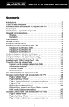
!!.-
STEP 3
STEP 4
STEP 5
V76MSE.book Page 90 Wednesday, May 19, 1999 1:25 PM
90
Chapter 4
Upgrading the System
Installing the Upgrade CPU
Note: Observe the ESD precautions on page 79 when installing or removing
a system component.
)%*-!.
!.-
2$!.8
!-
&!.*-$;%
!.;-
!--!.-
V76MSE.book Page 91 Wednesday, May 19, 1999 1:25 PM
91
-!.
!$+--21;
H21,,"
<A=$,7
%
Warning! The heatsink becomes very hot when the system is on. Never
touch the heatsink with any metal or with your hands.
V76MSE.book Page 92 Wednesday, May 19, 1999 1:25 PM
92
Chapter 4
Upgrading the System
Replacing the Hard Disk
2-8
-HI
%-
HI$%$
$
-
V76MSE.book Page 93 Wednesday, May 19, 1999 1:25 PM
93
!-
&HI-
%%
$$$8
$
V76MSE.book Page 94 Wednesday, May 19, 1999 1:25 PM
94
Chapter 4
Upgrading the System
!$-
-
Make sure that the other ends of the floppy disk drive cables are connected
to their corresponding connectors on the system board.
V76MSE.book Page 95 Wednesday, May 19, 1999 1:25 PM
95
Installing and Removing a PCI Card
Installing a PCI Card
/%!&%
-$%
!&
!&-$$
$!&
-
%
"$
5%%*)&"%$
!&
Removing a PCI Card
!&*%
<&$!&=
V76MSE.book Page 96 Wednesday, May 19, 1999 1:25 PM
96
Chapter 4
Upgrading the System
V76MSE.book Page 97 Wednesday, May 19, 1999 1:25 PM
97
Symbols
DH
A
CI
%!,D
D,
636
%%0%!C,
,%H
HH
HH
HH
B
1D,
1!6
D;LC3
,I
163J
43J
3,
3;
3J
3;
C3;
3J
3;
1!63,
C
VGGG9&333C;
,H
7
;;
7
;;
6
6
;;
;J
,7*,6
%*77
6J
77
D
&3H
DH
&"!,D
&!"",H
&!""73
&!""7C
&&
I,
&&IJ
%!6IH
I,
&"IH
01IJ
5W;9IH
5IH
5UX2G-"1I,
I,
!&)
IJ
!&)
I;
!&)
I;
!&)
I;
C9';GIJ
UI,
I,
&"!,D
E
D,
;C
;6
;C
;C
;C
)&C6
C3
,H
F
3VDH
3&&0H;
I
I
3
H
5"HI
5,D
V76MSE.book Page 98 Wednesday, May 19, 1999 1:25 PM
98
3C
3C
33
I
C6
97J
C6
9
%!6I
J
:,7
:,7
K
DH
L
CCD
M
D,
"
'2"19'E"1C;
"
6
CJ
CJ
CJ
"!&!H
9H3
O
6&II
I3
!&)I3
IC
%0;I3
*1I3
*1
IC
6%ID
ID*II
)%&"II
!YID*II
II
II
'0;ID
7;
7;
7,
H
P
%%,H
%
37
%!H
%"I7
!&)I7
I6
I7
X-I6
I6
I6
9I6
,D
;H
D
%!D7
&"!1!6D6
!&D7
D7
1!6D7
D7
R
5&&6,
S
&",H
,D
!DD
'D3
;D3
UDI
DI
1DI
!&)
DI
!&)
DI
!&)
D3
!&)
D3
UDI
D3
DI
DI
%0;DC
'D3
;D3
D3
H
7C
V76MSE.book Page 99 Wednesday, May 19, 1999 1:25 PM
99
3D
3I
3I
3I
3I
%93I
3D
T
;I
;D
;H
U
*1H*,D*HD
V
H,
,%H,
H,
9H,
W
?9C HC
?6CHC