1
More
More
More
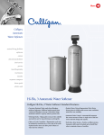
HI-FLO® 52
AUTOMATIC WATER SOFTENERS
SPECIFICATIONS
AND
OPERATING DATA
MODELS
Model 180 Model 300 Model 450 Model 600 Model 750 Model 900
1
Capacity ,
grains @
Maximum
pounds
@ Salt Dosage
1
Capacity ,
Minimum
2
Service Flow,
Continuous
Service Flow,
34
Peak
Pipe Size, NPTI
Resin Volume
Media Tank, dia. x ht.
Steel
Fiberglass
Brine Tank,
dia. x ht.
Ship. Wt., approx.
Fiberglass
300,000
450,000
600,000
750,000
900,000
90
150
225
300
375
450
grams @
11,664
19,440
29,160
38,879
48,599
58,320
kilograms
41
68
102
136
170
204
grains @
120,000
200,000
300,000
400,000
500,000
600,000
36
60
90
120
150
180
grams @
7,776
12,960
19,440
25,920
32,400
38,880
kilograms
16
27
41
54
68
82
gpm
67
78
90
97
95
104
m /hr
15
18
20
22
22
24
gpm
95
108
120
125
123
125
m /hr
22
25
27
28
28
28
in
2
2
2
2
2
2
cu. ft.
6
10
15
20
25
30
liters
170
283
425
566
708
850
in
20 x 54
24 x 54
30 x 54
36 x 60
36 x 60
42 x 60
cm
51 x 137
61 x 137
76 x 137
91 x 152
91 x 152
107 x 152
in
21 x 69
24 x 72
30 x 72
36 x 72
NA
NA
cm
53 x 175
61 x 183
76 x 183
91 x 183
NA
NA
in
24 x 48
30 x 48
30 x 48
36 x 48
42 x 48
42 x 48
cm
61 x 122
76 x 122
76 x 122
91 x 122
107 x 122
107 x 122
pounds
730
1050
1580
2050
2400
2750
kilograms
330
480
720
940
1090
1195
pounds
570
860
1250
1600
NA
NA
kilograms
260
390
570
730
NA
NA
pounds
@ Salt Dosage
Steel
180,000
3
3
1 Exchange capacities based on treating water containing 10 grains per gallon of hardness (expressed as calcium carbonate), free of color, oil, turbidity and at
a continuous flow rate of approximately 50 percent of the peak flow rate. These are nominal capacities and will vary with influent water characteristics, water
temperature, and other factors.
2 Continuous flow at 15 psi (103 kPa) pressure drop.
3 Peak flow at 25 psi (172 kPa) pressure drop.
4 Operation of a softener at peak flow rate for extended periods of time may result in a slight reduction of softening capacity. This is due to premature
hardness breakthrough.
NOTE: Operational, maintenance and replacement requirements are essential for this product as advertised.
Commercial Systems
©2000 Culligan
1-800-CULLIGAN
www.culligan.com
Printed in USA Rev. 4/00
DCO 992587
SL-0075
Moore Part No.46945
Hi-Flo 52
More
CAD File: Soft_HF52_stl.dwg
Hi-Flo 52
CAD File: Soft_HF52_frp.dwg
More
ENGINEER’S SPECIFICATION
AUTOMATIC WATER SOFTENER
HI-FLO® 52
1.0
1.1
1.2
1.2
2.0
2.1
CUSTOMER:
DATE:
SCOPE
Provide as indicated a vertical pressure type water softener system complete with pressure vessel, softening
resin, control valve, brine maker and electronic controller. The system will be of an approved design as
fabricated by a manufacturer regularly engaged in the production of water treatment equipment. All equipment
and material will be supplied in compliance with the specifications as intended for a complete and operational
system.
¨ (Open Bidding Arrangement)
Qualified manufacturers of water treatment equipment of the type specified are Culligan International Company
or the Engineer’s approved equal.
¨ (Closed Bidding Arrangement)
Qualified manufacturers of water softener equipment must be engaged in the manufacture of this equipment for
a period of not less than fifteen (15) years. Acceptable manufacturers are Culligan International Company or the
Engineer’s approved equal.
GENERAL DESCRIPTION
¨ (Selection for statement of specific model)
The system specifications are based on Culligan International model ________________________________.
The purpose of the Culligan International Series Hi-Flo® 52 automatic water softener will be to remove mineral
hardness from a known water supply to a level not to exceed ________ mg/l, as determined by an accepted
ASTM or EDTA test method, when the system is operated at ________ gpm and in accordance with the
operating instructions. The system will be capable of supplying ________ gallons of softened water between
regenerations based on the influent water analysis listed in Section 3.1 of this equipment specification.
The systems performance is rated at a design flow rate of ______ gpm with a rated pressure drop of ______
psi, and will be capable of a peak flow rate of ______ gpm for sustained periods of 90 minutes with a pressure
drop of ______ psi.
There shall be a quantity of ________ of the above described systems.
2.1
¨ (Selection for general statement)
The system, in compliance with the equipment specification, is described as an automatic _______________
water softener system meeting the performance and design data requirements as hereinafter specified.
3.0
PERFORMANCE AND DESIGN DATA
3.1
INFLUENT WATER ANALYSIS
Calcium, Ca:
Magnesium, Mg:
Total Hardness:
(Constituents above are expressed in ppm or mg/l as CaCO3 or as otherwise specified.)
Iron, Fe:
Manganese, Mn:
Total Dissolved Solids, TDS:
(Constituents above are expressed in ppm or mg/l.)
Turbidity, NTU:
Color:
pH:
More
3.2
DESIGN PARAMETERS
Normal System Flow & Pressure Drop:
gpm @ 15 PSI
Maximum System Flow & Pressure Drop:
gpm @ 25 PSI
Backwash/Rinse Flow:
gpm
Backwash Volume:
gallons nominal
Daily Water Usage:
gallons per day (gpd)
Daily Hours of Water Demand:
Operating Temperature Range:
40°–120°F
Operating Pressure Range (System):
30–100 PSI
Electrical Requirements:
120 Volt, 60 Hz, 1 phase (receptacle required)
”W x
”H
System Dimension (L x W x H):
”L x
3.3
¨ (ASTM soap test method)
EFFLUENT WATER QUALITY
3.3
¨ (Hardness EDTA test method)
EFFLUENT WATER QUALITY
4.0
EQUIPMENT SPECIFICATIONS
4.1
SOFTENER TANK(S)
Each system shall include _____ tank(s). Each softener tank shall be _____ inches in diameter. The sideshell
height shall be _____ inches, sufficient to allow for proper freeboard space above the resin bed for adequate
expansion of the resin during backwashing.
ZERO GPG HARDNESS
MG/L HARDNESS
4.1.0 Tank Construction
¨ (Standard vessel)
Tank(s) shall be electrical welded pressure vessel quality low carbon steel construction rated for 100 psig
working pressure.
¨ (ASME vessel)
Tank(s) shall be electrical welded pressure vessel quality low carbon steel construction rated for 125 psig
working pressure and hydrostatically tested at 50% in excess of the working pressure. Tank construction shall
conform to the latest edition of Section VIII for ASME Code pressure vessels and shall be so stamped and
certified.
¨ (Fiberglass vessel)
Tank(s) shall be manufactured of polyester reinforced by a continuous roving glass filament overwrap. The top
opening will be 4”-8 UN threaded and the tank bottom will be supported on a molded structural base.
4.1.1 Access Openings
¨ (Steel and ASME vessel)
Each tank will be equipped with openings for mineral filling and periodic inspection.
4.1.2 Tank Supports
¨ (Steel and ASME vessel)
Tank supports shall be structural steel legs that permit skid mounting and comply with Seismic Zone 4 loading
requirements, UBC importance factor 1.0.
¨ (Steel vessel)
4.1.3 Tank Finish – Exterior
Tank finish on the exterior shall be a high solids polyurethane monochromatic gloss enamel applied to a 1.25 to
1.50 mils DFT over a 1.00 to 1.25 mil DFT prime coat.
Culligan Hi-Flo® 52 Softener Engineer’s Specification
Page 2
More
¨ (Steel vessel)
4.1.4 Tank Finish – Interior
Tank interior shall have near white sandblast and be coated to 8 to 10 mil DFT with an epoxy phenolic designed
specifically as a high chemical resistant, non toxic, odorless protective coating. The lining shall meet the
requirements of the US Federal Register, Food and Drug Regulations, Title 21, Chapter 1, Paragraph 175.300.
4.2
INTERNAL DISTRIBUTION
4.2.1 The upper distribution system shall be of the baffle type to dispense water laterally to avoid channeling within
the resin bed.
¨ (20” models, 24” FG models)
4.2.2 The lower distribution system shall be of the single point distributor type, constructed of PVC pipe and a fine
slotted strainer to provide even flow distribution through the resin bed. The distribution system shall be
embedded in a two layer subfill of washed inorganic material to support the resin bed.
¨ (24” steel models, 30” and larger models)
4.2.2 The lower distribution system shall be of the hub and radial arm type, constructed of PVC pipe, a hub radial and
individual distributors arranged for even flow distribution through the resin bed. No distributor slots will face
upwards to minimize the opportunity for channeling. The distribution system shall be embedded in a single layer
subfill of washed inorganic material to support the resin bed.
4.3
MAIN OPERATING VALVE
The main operating valve shall be of a top mount design constructed of corrosion resistant alloy material and
sized with 2 inch NPTI inlet and outlet connections. The main operating valve will have provision for either left-to
right or right-to-left plumbing flow to simplify installation while maintaining a forward facing timer for ease of
service.
Hard-coat anodization of the valve shall be mandatory. The hard-anodized layer will be 2 mil in thickness or
greater and shall be final coated with a flouroplate polymer to further enhance corrosion resistance. The valve
shall be capable of passing a 1000 hour/5 percent salt spray test without signs of corrosion. The valve finishing
process shall be considered by the USEPA to be an environmentally friendly process. The valve body material
shall be considered as generally safe by the USFDA.
The main operating valve will provide water to service through two smooth-port diaphragm valves. The
diaphragm valves shall be slow opening and closing, free of water hammer. Regeneration will be controlled
through two (2) plastic pistons operating through Teflon® seals.
The main operating valve shall incorporate self adjusting flow regulators to control the rate of flow and prevent
resin loss during backwash, brine/rinse and fast rinse/refill steps of regeneration, regardless of system pressure
fluctuations between 30 and 100 psi.
The main operating valve shall be designed and manufactured by the same manufacturer as the water softener
system.
¨ (Single units only – hard water bypass)
The unit shall be supplied so that the valve will allow automatic bypass of untreated water during regeneration.
The bypass shall be integral to the main operating valve body and be capable of being easily modified to
prevent hard water bypass.
¨ (Single units only – NO hard water bypass)
The unit shall be supplied so that the valve will not allow automatic bypass of untreated water during
regeneration. The bypass shall be integral to the main operating valve body and be capable of being easily
modified to allow hard water bypass.
Culligan Hi-Flo® 52 Softener Engineer’s Specification
Page 3
More
4.4
CONTROLS
A fully integrated programmable micro-processor driven electronic controller shall be provided to automatically
cycle the main operating valve through the regeneration sequence.
The electronic controller shall be designed and manufactured by the same manufacturer as the water treatment
equipment.
The controller shall sequence all steps of an automatic regeneration and automatically return the softener to a
service or stand-by mode. The initiating time and/or volume setpoints shall automatically reset upon initiation of
the regeneration sequence.
The controller shall allow for a manual initiation of the automatic regeneration sequence by utilizing a
regeneration button on the face of the controller.
The controller shall be housed in an enclosure constructed to NEMA 3 enclosure standards. The controller shall
include a keypad, capable of programming all controller functions, located inside the enclosure. Also included
with the keypad shall be a fluorescent alpha-numeric display capable of showing all information necessary for
programming the controller and operating the softener.
4.4.1 System control options
¨ (Time Clock, Single Unit)
An operator selected program of a time-initiated regeneration for single units shall be available. The controller
shall be capable of being entirely programmed in the field without additional interface devices. The operator
shall be able to select regeneration to occur after a specified number of days. The electronic controller shall
indicate various functions that include time of day, time of regeneration, number of regenerations in the last
fourteen (14) days, number of days since the last regeneration and unit in regeneration.
¨ (Meter Initiated, Single Unit)
An operator selected program of immediate or delayed volume initiated regeneration for single units shall be
available. The controller shall be capable of being entirely programmed in the field without additional interface
devices. The electronic controller shall indicate various functions that include time of day, time of delayed
regeneration, instantaneous flow rate, volume remaining before next regeneration, number of regenerations in
the last fourteen (14) days, number of days since the last regeneration and unit in regeneration.
¨ (Aqua-Sensor® Initiated, Single Unit)
An operator selected program of immediate or delayed hardness initiated regeneration for single units shall be
available. An Aqua-Sensor® control probe will be inserted into the resin bed and will sense the need for
regeneration based on the differential water hardness reading and will signal the circuit board to initiate
regeneration. The system will compensate for variations in water hardness and temperature and will require no
field adjustments when operated within the normal temperature range of the softener. The controller shall be
capable of being entirely programmed in the field without additional interface devices. The electronic controller
shall indicate various functions that include time of day, time of delayed regeneration, number of regenerations
in the last fourteen (14) days, number of days since the last regeneration and unit in regeneration.
¨ (Time Clock, Parallel Twin Unit)
An operator selected program of a time initiated regeneration for parallel twin configurations shall be available.
The controller shall be capable of being programmed in the field without additional interface devices. The
electronic controller shall indicate various functions that include time of day, time of regeneration, number of
regenerations in the last fourteen (14) days, number of days since the last regeneration and unit in
regeneration. The controller must communicate via a single pre-wired cable assembly, simultaneous
regenerations shall not be possible.
¨ (Meter Initiated, Parallel Twin Unit)
An operator selected program of immediate or delayed volume initiated regeneration for parallel twin
configurations shall be available. The controller shall be capable of being programmed in the field without
additional interface devices. The controller shall indicate various functions that include time of day, time of
delayed regeneration, instantaneous flow rate display, volume remaining before next regeneration, number of
regenerations in the last fourteen (14) days, the days since the last regeneration and indication if the softener is
in regeneration. The controller must communicate via a single pre-wired cable assembly, simultaneous
regenerations shall not be possible.
Culligan Hi-Flo® 52 Softener Engineer’s Specification
Page 4
More
¨ (Meter Initiated, Alternating Twin Unit)
An operator selected program of immediate volume initiated regeneration for alternating twin configurations
shall be available. The controller shall be capable of being programmed in the field without additional interface
devices. The controller shall indicate various functions that include time of day, instantaneous flow rate display,
volume remaining before next regeneration, number of regenerations in the last fourteen (14) days, the days
since the last regeneration and indication if the softener is in stand-by or regeneration. No external alternating
devices will be acceptable. The alternating function must be contained in the sequencing controller and each
controller must communicate via a single pre-wired cable assembly, simultaneous regenerations shall not be
possible.
¨ (Aqua-Sensor® Initiated, Parallel Twin Unit)
An operator selected program of immediate or delayed hardness initiated regeneration for parallel twin
configurations shall be available. An Aqua-Sensor® control probe will be inserted into the resin bed and will
sense the need for regeneration based on the differential water hardness reading and will signal the circuit
board to initiate regeneration. The system will compensate for variations in water hardness and temperature
and will require no field adjustments when operated within the normal temperature range of the softener. The
controller shall be capable of being programmed in the field without additional interface devices. The controller
shall indicate various functions that include time of day, time of delayed regeneration, number of regenerations
in the last fourteen (14) days, the days since the last regeneration and indication if the softener is in
regeneration. The controller must communicate via a single pre-wired cable assembly, simultaneous
regenerations shall not be possible.
¨ (Aqua-Sensor® Initiated, Alternating Twin Unit
An operator selected program of immediate hardness initiated regeneration for alternating twin configurations
shall be available. An Aqua-Sensor® control probe will be inserted into the resin bed and will sense the need for
regeneration based on the differential water hardness reading and will signal the circuit board to initiate
regeneration. The system will compensate for variations in water hardness and temperature and will require no
field adjustments when operated within the normal temperature range of the softener. The controller shall be
capable of being programmed in the field without additional interface devices. The controller shall indicate
various functions that include time of day, number of regenerations in the last fourteen (14) days, the days since
the last regeneration and indication if the softener is in stand-by or regeneration. No external alternating devices
will be acceptable. The alternating function must be contained in the sequencing controller and each controller
must communicate via a single pre-wired cable assembly, simultaneous regenerations shall not be possible.
4.4.2 In addition the following functions shall be provided as part of the system controller:
Memory back-up protection: The controller shall have memory back-up protection via at least two methods,
each capable of retaining the selected operating program and its default settings indefinitely.
Regeneration sequence timers: The controller shall allow control of up to three individual regeneration cycles,
each programmable from 0 - 99 minutes.
Lockout function: The controller shall include a lockout to prevent unauthorized personnel from altering program
data.
Regeneration override: The controller shall include a function to direct pre-programmed regeneration after 3
days without input signal (European requirement).
¨ (Included with metered unit and flow sensor selection – following two options)
Flow rate indication: The controller shall include a flow rate indicator. The flow rate shall be displayed through
the controller display.
Totalizer: The controller shall include a totalizer function. The totalizer value shall be displayed through the
controller display.
Culligan Hi-Flo® 52 Softener Engineer’s Specification
Page 5
More
¨ (Meter Initiated systems ONLY)
4.4.3 Flow Sensor(s)
¨ (1.5” Plastic Turbine Meter)
A flow sensor package shall be provided consisting of an turbine-type Hall Effect; the package shall include a
total of _____ flow sensors with fittings.
The fitting provided shall be a 1-1/2 inch threaded Noryl housing. A 4-foot length of cable shall be provided for
direct connection to the system controller.
The flow sensor package provided shall be functional within the flow range of 1 to 60 gpm.
The operating temperature/pressure range of flow sensor fittings shall be 34°F - 100°F at 140 psi max.
The wetted surfaces of the flow sensor shall be constructed of non-corroding materials.
The flow sensor shall have an accuracy to 2% over full range.
¨ (2.0” Meter)
A flow sensor package shall be provided consisting of an insertion-type Hall Effect flow transducer with an
appropriately sized installation fitting; the package shall include a total of _____ flow sensors with fittings.
The fitting provided shall be 2.0 inches, compatible with the specified piping. It will be designed to allow ease of
removal of the sensor for inspection without modification of the piping system. A 25-foot length of cable shall be
provided for direct connection to the system controller.
The flow sensor package provided shall be functional within the flow range of 3 to 275 gpm and will be provided
with a threaded tee flow sensor installation fitting.
The operating temperature/pressure range of flow sensor fittings shall be 34°F - 100°F at 140 psi max.
The wetted surfaces of the flow sensor shall be constructed of non-corroding materials such as polypropylene,
black Polyvinylidene (PVDF) and titanium.
The flow sensor shall have an accuracy to 1.5% over full range.
4.5
EXCHANGE RESIN
The ion exchange resin shall be virgin high capacity “standard mesh” of sulfonated polystyrene type stable over
the entire pH range with good resistance to bead fracture from attrition or osmotic shock. Each cubic foot of
resin will be capable of removing 30,000 grains of hardness as calcium carbonate when regenerated with 15
lbs. of salt. The resin shall be solid, of the proper particle size of 20-50 mesh, U.S. standard screen and will
contain no agglomerates, shells, plates or other shapes that might interfere with the normal function of the water
softener. The resin shall be manufactured to comply with the food additive regulation 21 CFR 173.25 as set
forth by the USFDA.
The system shall include _____ cubic feet of exchange resin per vessel and a total of _____ cubic feet of resin
for the system.
4.6
BRINE SYSTEM
Provide a complete brine system consisting of a plastic tank, salt platform, brine well, an automatic brine valve
and all necessary fittings for operation with the water softening system. The system shall consist of a combined
brine measuring and salt storage tank with salt platform. The tank will be sized ____ inches x _____ inches; the
system will include a total of _____ brine tank(s).
The brine tank will be equipped with a float operated non-corrosive field serviceable brine float valve for
automatic control of brine withdrawal and fresh water refill.
The brine valve will automatically open to admit brine to the resin tank during eduction and close automatically
providing positive shut-off to prevent air from entering the system. The brine valve will also regulate the flow of
soft water into the brine tank during refill. The brine valve works with the timed fill feature of the main operating
Culligan Hi-Flo® 52 Softener Engineer’s Specification
Page 6
valve controls to admit the correct volume of fresh water to the brine tank in accordance with the salt dosage
setting on the controls. The brine valve will include a float operated safety shut-off valve as a back up to the
timed refill from the main operating valve control to prevent brine tank overflow.
4.7
4.7.1
4.7.2
4.7.3
4.7.4
ACCESSORIES
(All Optional selections)
¨ Water test kits for hardness tests will be supplied.
¨ Pressure Gauges for hard water inlet and soft water outlet.
¨ Sampling Cocks for hard water inlet.
¨ Vacuum Breaker for protecting Fiberglass tanks from vacuum.
5.0
INSTRUCTIONS
_____ complete sets of installation, operating and maintenance manuals shall be provided.
6.0
FIELD SERVICE
The services of a factory authorized service representative can be made available to supervise, inspect and
provide operator training as required for initial start-up and system operation. Contact your local Culligan dealer
for service rates and scheduling.
7.0
WARRANTY
A single written warranty must be provided from the manufacturer of the water softener system covering
workmanship and materials.
Rev. 10/01
Culligan Hi-Flo® 52 Softener Engineer’s Specification
Page 7