1
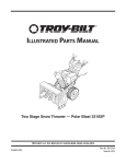
Operator’s Manual
45” SNOW THROWER
Model No. 247.88845
CAUTION: Before using
this product, read this
manual and follow all
safety rules and operating
instructions.
• SAFETY
• ASSEMBLY
• OPERATION
• MAINTENANCE
• PARTS LIST
• ESPAÑOL
Sears, Roebuck and Co., Hoffman Estates, IL 60179, U.S.A.
Visit our website: www.craftsman.com
FORM NO. 769-04062
5/30/2008
TABLE OF CONTENTS
Warranty Statement................................... Page 2
Safe Operation Practices........................... Pages 3-6
Safety Labels............................................. Page 7
Assembly................................................... Pages 8-11
Operation................................................... Pages 12-15
Service and Maintenance.......................... Pages 16-23
Off-Season Storage................................... Page 24
Troubleshooting......................................... Page 25
Parts List.................................................... Page 26-32
Repair Protection Agreement.................... Page 38
Español...................................................... Page 39
Service Numbers....................................... Back Cover
WARRANTY STATEMENT
Two -Year Limited Warranty on Craftsman Snow Thrower
When assembled, operated and maintained according to all supplied instructions, if this Craftsman product fails due to a defect in material or
workmanship within two years from the date of purchase, return it to any Sears store, Sears Parts & Repair Service Center or other Craftsman
outlet in the United States for free repair. In-home warranty service is available, but you will have to pay a trip charge.
This warranty covers only defects in material and workmanship. Sears will NOT pay for:
• Expendable items which become worn during normal use, such as skid shoes, shave plate and spark plugs.
• Repairs necessary because of operator negligence, including but not limited to, electrical and mechanical damage caused by improper
storage, bent crankshafts, failure to use the proper grade and amount of engine oil, or failure to maintain the equipment according to all
instructions contained supplied with the product.
• Engine (fuel system) cleaning or repairs caused by fuel determined to be contaminated or oxidized (stale). In general, fuel should be used
within 30 days of its purchase date.
This warranty applies for only 90 days if this product is ever used for commercial or rental purposes.
This warranty applies only while this product is used in the United States.
This warranty gives you specific legal rights, and you may also have other rights which vary from state to state.
Sears, Roebuck and Co., Hoffman Estates, IL 60179
PRODUCT SPECIFICATIONS
Engine Oil Type:
Engine Oil Capacity:
Fuel Capacity:
Spark Plug:
Spark Plug Gap:
MODEL NUMBER
Model Number..................................................................
Serial Number..................................................................
Date of Purchase..............................................................
SAE 5W-30
28 ounces
4 Quarts
Champion® RC12YC
.030”
Record the model number, serial number
and date of purchase above
© Sears Brands, LLC
2
SAFETY INSTRUCTIONS
WARNING
DANGER
This machine was built to be operated according to the safe operation practices in this manual. As with any type of power equipment,
carelessness or error on the part of the operator can result in serious
injury. This machine is capable of amputating fingers, hands, toes
and feet and throwing debris. Failure to observe the following safety
instructions could result in serious injury or death.
This symbol points out important safety instructions which, if not
followed, could endanger the personal safety and/or property of
yourself and others. Read and follow all instructions in this manual
before attempting to operate this machine. Failure to comply with
these instructions may result in personal injury. When you see this
symbol, HEED ITS WARNING!
WARNING
WARNING
California Proposition 65
Your Responsibility—Restrict the use of this power machine to
persons who read, understand and follow the warnings and instructions in this manual and on the machine.
Engine Exhaust, some of its constituents, and certain vehicle
components contain or emit chemicals known to State of California
to cause cancer and birth defects or other reproductive harm.
SAVE THESE INSTRUCTIONS!
Training
Preparation
•
Thoroughly inspect the area where the equipment is to be used.
Remove all doormats, newspapers, sleds, boards, wires and other
foreign objects, which could be tripped over or thrown by the auger/
impeller.
• Always wear safety glasses or eye shields during operation and
while performing an adjustment or repair to protect your eyes.
Thrown objects which ricochet can cause serious injury to the
eyes.
• Do not operate without wearing adequate winter outer garments.
Do not wear jewelry, long scarves or other loose clothing, which
could become entangled in moving parts. Wear footwear which
will improve footing on slippery surfaces.
• Use a grounded three-wire extension cord and receptacle for all
machines with electric start engines.
• Adjust collector housing height to clear gravel or crushed rock
surfaces.
• Disengage all control levers before starting the engine.
• Never attempt to make any adjustments while engine is running,
except where specifically recommended in the operator’s manual.
• Let engine and machine adjust to outdoor temperature before
starting to clear snow.
•
•
•
•
•
•
Read, understand, and follow all instructions on the machine and
in the manual(s) before attempting to assemble and operate.
Keep this manual in a safe place for future and regular reference
and for ordering replacement parts.
Be familiar with all controls and their proper operation. Know how
to stop the machine and disengage them quickly.
Never allow children under 14 years of age to operate this
machine. Children 14 and over should read and understand the
instructions and safe operation practices in this manual and on
the machine and be trained and supervised by an adult.
Never allow adults to operate this machine without proper
instruction.
Thrown objects can cause serious personal injury. Plan your
snow-throwing pattern to avoid discharge of material toward
roads, bystanders and the like.
Keep bystanders, pets and children at least 75 feet from the
machine while it is in operation. Stop machine if anyone enters
the area.
Exercise caution to avoid slipping or falling, especially when
operating in reverse.
3
SAFETY INSTRUCTIONS
Safe Handling of Gasoline
To avoid personal injury or property damage use extreme care in
handling gasoline. Gasoline is extremely flammable and the vapors are
explosive. Serious personal injury can occur when gasoline is spilled
on yourself or your clothes which can ignite. Wash your skin and
change clothes immediately.
• Use only an approved gasoline container.
• Extinguish all cigarettes, cigars, pipes and other sources
of ignition.
• Never fuel machine indoors.
• Never remove gas cap or add fuel while the engine is hot
or running.
• Allow engine to cool at least two minutes before refueling.
• Never over fill fuel tank. Fill tank to no more than ½ inch
below bottom of filler neck to provide space for fuel
expansion.
• Replace gasoline cap and tighten securely.
• If gasoline is spilled, wipe it off the engine and equipment.
Move machine to another area. Wait 5 minutes before
starting the engine.
• Never store the machine or fuel container inside where
there is an open flame, spark or pilot light (e.g. furnace,
water heater, space heater, clothes dryer etc.).
• Allow machine to cool at least 5 minutes before storing.
• Never fill containers inside a vehicle or on a truck or trailer
bed with a plastic liner. Always place containers on the
ground away from your vehicle before filling.
• If possible, remove gas-powered equipment from the truck
or trailer and refuel it on the ground. If this is not possible,
then refuel such equipment on a trailer with a portable
container, rather than from a gasoline dispenser nozzle.
• Keep the nozzle in contact with the rim of the fuel tank or
container opening at all times until fueling is complete. Do
not use a nozzle lock-open device.
•
•
•
•
•
•
•
•
•
•
•
•
•
Operation
•
•
•
•
•
•
•
Do not put hands or feet near rotating parts, in the auger/impeller
housing or chute assembly. Contact with the rotating parts can
amputate hands and feet.
The auger/impeller control lever is a safety device. Never bypass
its operation. Doing so makes the machine unsafe and may cause
personal injury.
The control levers must operate easily in both directions and
automatically return to the disengaged position when released.
Never operate with a missing or damaged chute assembly. Keep
all safety devices in place and working.
Never run an engine indoors or in a poorly ventilated area. Engine
exhaust contains carbon monoxide, an odorless and deadly gas.
Do not operate machine while under the influence of alcohol or
drugs.
Muffler and engine become hot and can cause a burn. Do not
touch. Keep children away.
•
4
Exercise extreme caution when operating on or crossing gravel
surfaces. Stay alert for hidden hazards or traffic.
Exercise caution when changing direction and while operating on
slopes.
Plan your snow-throwing pattern to avoid discharge towards
windows, walls, cars etc. Thus, avoiding possible property
damage or personal injury caused by a ricochet.
Never direct discharge at children, bystanders and pets or allow
anyone in front of the machine.
Do not overload machine capacity by attempting to clear snow at
too fast of a rate.
Never operate this machine without good visibility or light. Always
be sure of your footing and keep a firm hold on the handles. Walk,
never run.
Disengage power to the auger/impeller when transporting or not
in use.
Never operate machine at high transport speeds on slippery
surfaces. Look down and behind and use care when backing up.
If the machine should start to vibrate abnormally, stop the engine,
disconnect the spark plug wire and ground it against the engine.
Inspect thoroughly for damage. Repair any damage before
starting and operating.
Disengage all control levers and stop engine before you leave
the operating position (behind the handles). Wait until the auger/
impeller comes to a complete stop before unclogging the chute
assembly, making any adjustments, or inspections.
Never put your hand in the discharge or collector openings.
Always use the clean-out tool provided to unclog the discharge
opening. Do not unclog chute assembly while engine is running.
Shut off engine and remain behind handles until all moving parts
have stopped before unclogging.
Use only attachments and accessories approved by the manufacturer (e.g. wheel weights, tire chains, cabs etc.).
When starting engine, pull cord slowly until resistance is felt, then
pull rapidly. Rapid retraction of starter cord (kickback) will pull
hand and arm toward engine faster than you can let go. Broken
bones, fractures, bruises or sprains could result.
If situations occur which are not covered in this manual, use care
and good judgment. Contact Customer Support for assistance
and the name of your nearest servicing dealer.
SAFETY INSTRUCTIONS
Maintenance & Storage
Do not modify engine
•
To avoid serious injury or death, do not modify engine in any way.
Tampering with the governor setting can lead to a runaway engine and
cause it to operate at unsafe speeds. Never tamper with factory setting
of engine governor.
•
•
•
•
•
•
•
•
•
•
•
•
•
Never tamper with safety devices. Check their proper operation
regularly. Refer to the maintenance and adjustment sections of
this manual.
Before cleaning, repairing, or inspecting machine disengage all
control levers and stop the engine. Wait until the auger/impeller
come to a complete stop. Disconnect the spark plug wire and
ground against the engine to prevent unintended starting.
Check bolts and screws for proper tightness at frequent intervals
to keep the machine in safe working condition. Also, visually
inspect machine for any damage.
Do not change the engine governor setting or over-speed the
engine. The governor controls the maximum safe operating speed
of the engine.
Snow thrower shave plates and skid shoes are subject to wear
and damage. For your safety protection, frequently check all
components and replace with original equipment manufacturer’s
(OEM) parts only. “Use of parts which do not meet the original
equipment specifications may lead to improper performance and
compromise safety!”
Check control levers periodically to verify they engage and disengage properly and adjust, if necessary. Refer to the adjustment
section in this operator’s manual for instructions.
Maintain or replace safety and instruction labels, as necessary.
Observe proper disposal laws and regulations for gas, oil, etc. to
protect the environment.
Prior to storing, run machine a few minutes to clear snow from
machine and prevent freeze up of auger/impeller.
Never store the machine or fuel container inside where there is an
open flame, spark or pilot light such as a water heater, furnace,
clothes dryer etc.
Always refer to the operator’s manual for proper instructions on
off-season storage.
Check fuel line, tank, cap, and fittings frequently for cracks or
leaks. Replace if necessary.
Do not crank engine with spark plug removed.
According to the Consumer Products Safety Commission (CPSC)
and the U.S. Environmental Protection Agency (EPA), this product
has an Average Useful Life of seven (7) years, or 60 hours of
operation. At the end of the Average Useful Life have the machine
inspected annually by an authorized service dealer to ensure that
all mechanical and safety systems are working properly and not
worn excessively. Failure to do so can result in accidents, injuries
or death.
Notice Regarding Emissions
Engines which are certified to comply with California and federal
EPA emission regulations for SORE (Small Off Road Equipment) are
certified to operate on regular unleaded gasoline, and may include
the following emission control systems: Engine Modification (EM),
Oxidizing Catalyst (OC), Secondary Air Injection (SAI) and Three Way
Catalyst (TWC) if so equipped.
Spark Arrestor
WARNING
This machine is equipped with an internal combustion engine and
should not be used on or near any unimproved forest-covered,
brushcovered or grass-covered land unless the engine’s exhaust
system is equipped with a spark arrester meeting applicable local or
state laws (if any)
If a spark arrester is used, it should be maintained in effective working
order by the operator. In the State of California the above is required
by law (Section 4442 of the California Public Resources Code). Other
states may have similar laws. Federal laws apply on federal lands.
A spark arrester for the muffler is available through your nearest Sears
Parts and Repair Service Center.
5
SAFETY INSTRUCTIONS
Safety Symbols
This page depicts and describes safety symbols that may appear on this product. Read, understand, and follow all instructions on the machine
before attempting to assemble and operate.
Symbol
Description
READ THE OPERATOR’S MANUAL(S)
Read, understand, and follow all instructions in the manual(s) before attempting to assemble and
operate
WARNING— ROTATING BLADES
Keep hands out of inlet and discharge openings while machine is running. There are rotating blades
inside
WARNING— ROTATING BLADES
Keep hands out of inlet and discharge openings while machine is running. There are rotating blades
inside
WARNING— ROTATING AUGER
Do not put hands or feet near rotating parts, in the auger/impeller housing or chute assembly.
Contact with the rotating parts can amputate hands and feet.
WARNING—THROWN OBJECTS
This machine may pick up and throw and objects which can cause serious personal injury.
WARNING—GASOLINE IS FLAMMABLE
Allow the engine to cool at least two minutes before refueling.
WARNING— CARBON MONOXIDE
Never run an engine indoors or in a poorly ventilated area. Engine exhaust contains carbon
monoxide, an odorless and deadly gas.
WARNING— ELECTRICAL SHOCK
Do not use the engine’s electric starter in the rain
6
SAFETY LABELS
DANGER
1. KEEP AWAY FROM ROTATING IMPELLER
AND AUGER. CONTACT WITH IMPELLER OR
AUGER CAN AMPUTATE HANDS AND FEET.
2. USE CLEAN-OUT TOOL TO UNCLOG
DISCHARGE CHUTE.
3. DISENGAGE CLUTCH LEVERS, STOP ENGINE ,
AND REMAIN BEHIND HANDLES UNTIL ALL
MOVING PARTS HAVE STOPPED BEFORE
UNCLOGGING OR SERVICING MACHINE.
4. TO AVOID THROWN OBJECTS INJURIES,
NEVER DIRECT DISCHARGE AT BYSTANDERS.
USE EXTRA CAUTION WHEN OPERATING ON
GRAVEL SURFACES.
5. READ OPERATOR'S MANUAL.
CLEAN-OUT TOOL
DANGER
aVoiD injUrY froM
roTaTing aUger keeP HanDS, feeT
anD CLoTHing aWaY.
DANGER
NEVER PUT HAND IN CHUTE. CONTACT WITH
ROTATING PARTS CAN AMPUTATE FINGERS
AND HANDS.
SHUT OFF ENGINE AND WAIT UNTIL AL L
MOVING PARTS HA VE STOPPED BEFORE
UNCLOGGING.
USE CLEAN-OUT TOOL OR WOODEN STICK TO
UNCLOG DISCHARGE CHUTE.
7
ASSEMBLY
NOTE: References to right or left side of the snow thrower are
determined from behind the unit in the operating position (standing
directly behind the snow thrower, facing the handle panel).
Removing From Crate
1. Remove screws from the bottom of the crate securing the sides,
and ends of the shipping crate.
2. Lift off the top off of the crate and set out of the way of the
assembly area.
3. Remove and discard plastic bag that covers unit.
4. Remove any loose parts included with unit (e.g., Operator’s
Manual, etc.).
5. Push down on the lower handle and pull unit back out of crate.
6. Make certain the crate has been completely emptied before
discarding it.
assembly
Figure 1
1. Make certain the springs at the lower end of the auger and drive cables are securely hooked into their respective actuator
bracket before pivoting the handle upward. Refer to Fig. 10.
a. Place the shift lever in the F6 position.
b. Remove the lower wing knob and carriage bolt from each side of the upper handle. Pull up on upper handle as shown
in Fig. 1. Align upper handle with the lower handle. Again, make certain the springs at the lower end of the auger and drive cables are securely hooked into their respective
actuator bracket. Also, remove any rubber bands securing the cables to the wing nuts.
2. a. Secure the upper handle and lower handle with the two wing knobs and carriage bolts removed earlier.
b. Tighten the two wing knobs already installed in the upper holes to firmly secure the upper handle and support tubes.
3. Align the upper and lower shift rods, then slide the shift rod connector down over the end of the lower shift rod. Tap the
connector until the lower rod is completely through the connector. See Fig. 2.
Figure 2
NOTE: If the connector is not properly assembled, the shift rod will
pivot and you will not be able to properly change speeds or direction.
NOTE: If the full range of speeds (forward and reverse) can not be
achieved, refer to the “Making Adjustments” section.
4.
a. Cut the cable tie securing the chute assembly to the lower chute crank rod for shipping purposes.
b. Remove the internal cotter pin from the upper chute crank. Slide the upper chute crank into the sleeve on the lower
chute crank. See Fig. 3.
c. Align the hole in the upper chute crank with the hole in the sleeve (If necessary, use a pair of pliers to assist in aligning holes). Insert the internal cotter pin through the holes to
secure the chute crank. See Fig. 3.
5. Remove lock nuts and screws securing one of the flange keepers
to the chute assembly.
a
b
Figure 3
8
ASSEMBLY
6. Place chute assembly onto chute base as shown in Fig. 4, making sure that the notches engage with the spiral end of chute directional control.
7. Secure flange keeper removed earlier with lock nuts and screws. Tighten down nuts securing the other two flange keepers. See Fig. 5.
8. If not already done, slip the cables that run from the handle panel to the discharge chute into the cable guide extending over
the top of the engine. See Fig. 4.
9. Normally the cable ties holding the steering cables against the
handle are loosely installed on each side of the lower handle at the factory. Pull the cable ties tight to secure. Cut the excess from the ends of cable ties.
The extension cord is fastened with a cable tie to the rear of the auger
housing for shipping purposes. Cut the cable tie and remove it before
operating the snow thrower.
Set-Up
Chute Clean-Out Tool
Figure 4
A chute clean-out tool is fastened to the top of the auger housing
with a mounting clip. See Fig. 6. The tool is designed to clear a chute
assembly of ice and snow. This item, along with the extension cord, is
fastened with a cable tie at the factory, which you were instructed to
cut in the previous section.
Drift Cutters
1. Remove the two screws and lock nuts that secure each drift
cutter, and remove them from the sides of the auger housing.
WARNING
Never use your hands to clear a clogged chute assembly. Shut
off engine and remain behind handles until all moving parts have
stopped before using the clean-out tool to clear the chute assembly.
2. Turn the drift cutters around and position them as shown in Fig. 7
to the outside of the auger housing.
3. Attach the drift cutters with the screws and lock nuts removed
earlier.
Figure 5
Chute Clean-out Tool
Figure 7
Figure 6
9
ASSEMBLY
Tire Pressure
Before operating, check tire pressure. Refer to the tire sidewall for
exact tire manufacturer’s recommended or maximum psi.
NOTE: If the tire pressure is not equal in both tires, the unit may not
travel in a straight path and the shave plate may wear unevenly.
Adjustments
Skid Shoes
The snow thrower skid shoes are adjusted upward at the factory for
shipping purposes. Adjust them downward, if desired, prior to operating the snow thrower.
• For close snow removal on a smooth surface, raise skid shoes
higher on the auger housing.
CAUTION
It is not recommended that you operate this snow thrower on gravel
as it can easily pick up and throw loose gravel, causing personal
injury or damage to the snow thrower and surrounding property.
•
Figure 8
Use a middle or lower position when the area to be cleared is
uneven.
NOTE: If you choose to operate the snow thrower on a gravel surface,
keep the skid shoes in position for maximum clearance between the
ground and the shave plate.
To adjust the skid shoes:
1. Loosen the six hex nuts (three on each side) and carriage bolts.
Move skid shoes to desired position. See Fig. 8.
2. Make certain the entire bottom surface of skid shoe is against the
ground to avoid uneven wear on the skid shoes.
3. Retighten nuts and bolts securely.
Chute Tilt Control
Shift Lever
Auger
Control
Drive
Control
Auger
Control
Cable
Drive
Control
Cable
Figure 9
10
ASSEMBLY
Testing Auger Drive Control
When the auger control is released and in the disengaged “up” position, the cable should have very little slack, but should NOT be tight.
Refer to Fig. 9 for location of controls.
WARNING
Prior to operating your snow thrower, carefully read and follow all
instructions below. Perform all adjustments to verify your snow
thrower is operating safely and properly.
1. In a well-ventilated area, start the snow thrower engine as
instructed in the Operation section.
2. While standing in the operator’s position (behind the snow
thrower), engage the auger control and allow the auger to remain
engaged for approximately ten seconds before releasing the
auger control. Repeat this several times.
3. With the engine running and the auger control in the disengaged
“up” position, walk to the front of the machine. C
onfirm that the
auger has completely stopped rotating and shows no signs of
motion.
4. If the auger shows any signs of rotating, immediately return to the
operator’s position and shut off the engine. Wait for all moving
parts to stop before readjusting the auger control cable.
Figure 10
Testing Wheel Drive Control & Speed Selector
Shift Lever
Refer to Fig. 9 for location of controls.
1. Move the shift lever into sixth (6) position.
2. With the wheel drive control released, push the snow thrower
forward, then pull it back. The machine should move freely.
3. Engage the drive control and attempt to move the machine both
forward and back, resistance should be felt.
4. Move the shift lever into the fast reverse (R2) position and repeat
the previous two steps.
If you experienced resistance rolling the unit, either when repositioning
the shift lever from 6 to R2 or when attempting to move the machine
with the drive control released, adjust the drive control immediately.
See Adjusting Drive and Auger Controls.
Figure 11
Adjusting Wheel Drive & Auger Controls
1. From beneath the handle, pull downward on the appropriate cable
and unhook the spring found on the end of the cable from its
respective actuator bracket. Refer to Fig. 9 and 10.
2. Slide the spring up the cable to expose the cable coupler threads
and lock nut. Refer to Fig. 11.
3. If adjusting the drive cable, thread the lock nut outward (down the
coupler towards the end fo the thread) to lengthen the cable and
allow the unit to move freely when the control is released. Thread
the lock nut inward (up the coupler towards the cable) to shorten
the cable to reduce slippage and prevent the machine from being
easily moved with the drive control engaged.
WARNING
Do not over-tighten the cable. Over-tightening may prevent the auger
from disengaging and compromise the safety of the snow thrower.
4. If adjusting the auger cable, thread the lock nut down the coupler
towards the end of the thread to lengthen the cable as necessary
to stop the auger from turning when the control is released.
5. Reattach the spring to the rearmost hole in the actuator bracket.
6. Repeat the wheel drive and auger control tests to verify proper
adjustment. Repeat previous steps if necessary to attain proper
adjustment of each cable.
11
OPERATION
Drive Control
Shift Lever
Two-Way Chute Control™
Headlight
Auger Control
Drift
Cutters
Wheel Steering
Control
Chute
Assembly
Chute Directional
Control
Fuel Cap
Choke
Primer
Oil Fill
Ignition
Key
Clean-Out Tool
Augers
Recoil Starter
Handle
Skid Shoe
Starter
Button
Oil Drain
Electric Starter Outlet
Figure 11
NOTE: Do not turn the ignition key in an attempt to start the engine.
Now that you have setup your snow thrower, it’s important to become
Doing so may cause it to break.
acquainted with its controls and features. Refer to Figure 11.
Speed Selector Shift Lever
The shift lever is located on the right side of the handle panel.
Place the shift lever into any of eight positions to control the
direction of travel and ground speed.
Forward
Your snow thrower has six forward (F) speeds. Position one (1) is
the slowest and position six (6) is the fastest.
Reverse
Your snow thrower has two reverse (R) speeds. One (1) is the
slower and two (2) is the faster.
Choke Control
The choke control is found on the rear of the
engine and is activated by rotating the knob
clockwise. Activating the choke control closes the
choke plate on the carburetor and aids in starting
the engine.
Primer
Depressing the primer forces fuel directly into the engine’s carburetor
to aid in cold-weather starting.
Oil Fill
Ignition Key
The ignition key is a safety device. It must be fully inserted in order for
the engine to start. Remove the ignition key when the snow thrower is
not in use.
Engine oil level can be checked and oil added through the oil fill.
Meets ANSI Safety Standards
Craftsman Snow Throwers conform to the safety standard of the American National Standards Institute (ANSI).
12
OPERATION
On / Off switch
DRIVE
CONTROL
Press into the ON position when starting the engine and will shut off
the engine when moved into the OFF position.
Recoil Starter Handle
This handle is used to manually start the engine.
Electric Starter Button
Pressing the electric starter button engages the engine’s electric
starter when plugged into a 120V power source.
Electric Starter Outlet
GO
Requires the use of a three-prong outdoor extension cord (included)
and a 120V power source/wall outlet.
NOTE: Always release the wheel drive control before changing
speeds. Failure to do so will result in increased wear on your machine’s
drive system.
Augers
Two-way chute Control™
When engaged, the augers rotate and draw snow into the auger
housing.
Chute Assembly
Snow drawn into the auger housing is discharged out the chute
assembly.
Gas Cap
Unthread the gas cap to add gasoline to the fuel tank.
The distance snow is thrown can be changed by adjusting the angle
of the chute assembly. Move the chute control forward to decrease the
distance, toward the rear to increase.
Chute Directional Control
The chute directional control is located on the left side of the snow
thrower.
• To change the direction in which snow is thrown, crank clockwise to
discharge to the left and counterclockwise to discharge to the right.
Skid Shoes
Position the skid shoes based on surface conditions. Adjust upward
for hard-packed snow. Adjust downward when operating on gravel or
crushed rock surfaces.
Auger Control
AUGER
CONTROL
Wheel Steering Controls
GO
The left and right wheel steering controls are located on the underside
of the handles. Squeeze the right control to turn right; squeeze the left
control to turn left.
NOTE: Operate the snow thrower in open areas until you are familiar
with these controls.
Headlight
The auger control is located on the left handle. Squeeze the control
grip against the handle to engage the augers and start snow throwing
action. Release to stop.
The headlight is located on top of the handle panel. It may be adjusted
by loosening the screws on each side of the light housing, pivoting the
light up or down, and retightening the screws.
Wheel Drive Control /Auger Control
Lock
Drift cutters
The wheel drive control is located on the right handle. Squeeze the
control grip against the handle to engage the wheel drive. Release
to stop. The Wheel drive control also locks the auger control so you
can operate the chute directional control without interrupting the snow
throwing process. If the auger control is engaged simultaneously with
the wheel drive control, the operator can release the auger control (on
the left handle) and the augers will remain engaged. Release both
controls to stop the augers and wheel drive.
The drift cutters are designed for use in deep snow. Their use is
optional for normal snow conditions.
Clean-Out Tool
The chute clean-out tool is conveniently fastened to the rear of the
auger housing with a mounting clip. Should snow and ice become
lodged in the chute assembly during operation, proceed as follows to
safely clean the chute assembly and chute opening.
13
OPERATION
Clean-Out Tool
WARNING
Never use your hands to clear a clogged chute assembly. Shut
off engine and remain behind handles until all moving parts have
stopped before unclogging.
The chute clean-out tool is conveniently fastened to the rear of the
auger housing with a mounting clip. Should snow and ice become
lodged in the chute assembly during operation, proceed as follows to
safely clean the chute assembly and chute opening:
1. Release both the Auger Control and the Wheel drive control.
2. Stop the engine by removing the ignition key.
3. Remove the clean-out tool from the clip which secures it to the
rear of the auger housing.
4. Use the shovel-shaped end of the clean-out tool to dislodge and
scoop any snow and ice which has formed in and near the chute
assembly.
5. Refasten the clean-out tool to the mounting clip on the rear of
the auger housing, reinsert the ignition key and start the snow
thrower’s engine.
6. While standing in the operator’s position (behind the snow
thrower), engage the auger control for a few seconds to clear any
remaining snow and ice from the chute assembly.
•
•
•
•
Starting The Engine
1. Make certain both the auger control and wheel drive control are in
the disengaged (released) position.
2. Insert ignition key into slot. Make sure it snaps into place. Do not
attempt to turn the key.
NOTE: The engine cannot start without the key is fully inserted into the
ignition switch.
Electric Starter
Determine that your home’s wiring is a three-wire grounded system.
Ask a licensed electrician if you are not certain.
WARNING
Before Starting Engine
The optional electric starter is equipped with a grounded three-wire
power cord and plug, and is designed to operate on 120 volt AC
household current. It must be used with a properly grounded threeprong receptacle at all times to avoid the possibility of electric shock.
Follow all instructions carefully prior to operating the electric starter.
WARNING
Read, understand, and follow all instructions and warnings on the
machine and in this manual before operating.
Oil
The unit was shipped with oil in the engine. Check oil level before each
operation to ensure adequate oil in the engine. For further instructions,
refer to the Service & Maintenance section of this manual.
1. Remove the dipstick from the oil fill.
2. Check and make sure that the level of oil is up to the FULL mark
on the dipstick.
3. If the oil level is not up to FULL, pour fresh motor oil (5W-30, with
a minimum classification of SF/SG/SH/SJ) slowly through the
opening. Replace oil fill dipstick and check oil level again.
Gasoline
•
•
Store gasoline in a clean, approved container and keep the cap in
place on the container.
Make sure that the container from which you pour the gasoline is
clean and free from rust or other foreign particles.
If you have a grounded three-prong receptacle, proceed as follows:
1. Plug the extension cord into the outlet located on the engine’s
surface. Plug the other end of extension cord into a three-prong
120-volt, grounded, AC outlet in a well-ventilated area.
2. Rotate choke control to FULL
choke position (for a cold
engine start).
NOTE: If the engine is already warm, place choke control in the OFF
position instead of FULL
.
3. Depress primer. If it is 15°F or higher push primer two times, if
below 15°F, push primer four times.
4. Push rocker switch to ON position.
5. Push starter button to start engine.
CAUTION
To prolong starter life, use short starting cycles (5 seconds maximum,
then wait one minute).
WARNING
Use extreme care when handling gasoline. Gasoline is extremely
flammable and the vapors are explosive. Never fuel the machine
indoors or while the engine is hot or running. Extinguish cigarettes,
cigars, pipes and other sources of ignition.
NOTE: A plastic dust cap may be found inside the fuel fill opening.
Remove and discard, if present.
Always fill the fuel tank outdoors and use a funnel or spout to
prevent spilling.
Fill fuel tank with clean, fresh, unleaded gasoline with a minimum
of 85 octane. Fresh fuel prevents gum from forming in the fuel
system or on essential carburetor parts. Purchase fuel in a
quantity that can be used within 30 days.
Never fill the fuel tank completely. Fill the tank to within 1-1/2”
from the top to provide space for expansion of fuel.
Make sure to wipe off any spilled fuel before starting the engine.
6. Once the engine starts, release starter button.
7. Allow the engine to warm up several minutes, adjusting choke
toward RUN position. Wait until engine runs smoothly before each
choke adjustment.
8. When disconnecting the extension cord, always unplug the end at the three-prong wall outlet before unplugging the opposite end from the snow thrower.
14
OPERATION
Recoil Starter
Replacing Shear Pins
1. Rotate choke control to CHOKE
position.
2. Depress primer. If it is 15°F or higher push primer two times, if
below 15°F, push primer four times.
3. Push rocker switch to ON position.
4. Grasp the recoil starter handle and slowly pull the rope out. At
the p oint where it becomes slightly harder to pull the rope, slowly
allow the rope to recoil.
5. Pull the starter handle with a firm, rapid stroke. Do not release the handle and allow it to snap back. Keep a firm hold on the
starter handle and allow it to slowly recoil.
6. Allow the engine to warm up several minutes, adjusting choke
toward RUN position. Wait until engine runs smoothly before each
choke adjustment.
The augers are secured to the spiral shaft with two shear pins and cotter pins. If the auger should strike a foreign object or ice jam, the snow
thrower is designed so that the shear pins may shear. If the augers will
not turn, check to see if the pins have sheared. See Figure 12.
CAUTION
NEVER replace the auger shear pins with anything other than OEM
Part No. 738-04155 replacement shear pins. Any damage to the
auger gearbox or other components as a result of failing to do so will
NOT be covered by your snow thrower’s warranty.
WARNING
Always turn off the snow thrower’s engine and remove the key prior to
replacing shear pins.
Stopping The Engine
Run engine for a few minutes before stopping to help dry off any
moisture on the engine.
1. Push the On / Off switch to the OFF position.
CAUTION
Do NOT move the choke control to CHOKE
position to stop
the engine. Backfire or engine damage may occur.
2. Remove the ignition key and store in a safe place.
3. Wipe all snow and moisture from the area around the engine as
well as the area in and around the wheel drive control and auger
control. Also, engage and release both controls several times.
To Engage Wheel Drive
1. Move shift lever into one of the six forward (F) positions or two
reverse (R) positions. Select a speed appropriate for the snow
conditions and a pace you’re comfortable with.
NOTE: When selecting a Drive Speed, use the slower speeds until
you are comfortable and familiar with the operation of the snow
thrower.
Figure 12
2. Squeeze the wheel drive control against the handle the snow
thrower will move. Release it and drive motion will stop.
NOTE: NEVER reposition the shift lever (change speeds or direction
of travel) without first releasing the wheel drive control and bringing
the snow thrower to a complete stop. Doing so will result in premature
wear to the snow thrower’s drive system.
To Engage Augers
1. To engage the augers and start throwing snow, squeeze the
auger control against the left handle. Release to stop the augers.
15
SERVICE AND MAINTENANCE
ENGINE MAINTENANCE
fULL
WARNING
Before lubricating, repairing, or inspecting, disengage all controls and
stop engine. Wait until all moving parts have come to a complete stop.
Remove the ignition key to prevent unintended firing of the engine.
Checking Engine Oil
e sure engine is upright and level
B
Unscrew oil fill cap from oil filler tube and wipe dipstick clean.
Screw oil fill cap back into oil filler tube. Tighten securely.
Unscrew and remove oil fill cap from oil filler tube. Note oil level.
If oil reading on dipstick is below “ADD” mark, slowly add oil to
reach “FULL” level. See Figure 13.
5. Screw oil fill cap back into oil filler tube. Tighten securely.
6. Wipe away any spilled oil.
aDD
1.
2.
3.
4.
Maintain oil level
at FULL
Changing Engine Oil
To avoid engine damage, it is important to:
• Check oil level before each use and every eight operating hours.
• Change oil after first 5 to 8 operating hours and every 50 operating hours or once a season thereafter.
1. Place engine level and remove safety key.
2. With engine OFF but still warm, remove oil drain plug and drain oil
into an appropriate receptacle. See Figure 13.
Figure 13
CAUTION
Oil FIll
Used oil is a hazardous waste product. Dispose of used oil properly.
Do not discard with household waste. Check with your local authorities or Sears Service Center for safe disposal/recycling facilities.
3. Reinstall oil drain plug and tighten securely.
4. Refill the engine with recommended oil. See Recommended Oil Usage chart. The engine’s oil capacity is 20 ounces.
Recommended Oil Usage
Oil Drain
5W-30, 10W-30
Synthetic 5W-30, 10W-30
O
-20 F
20 F
0F
O
O
-20 C
-10 C
-30 C
O
O
O
O
32 F
0C
O
40 F
60 F
O
O
10 C
O
O
O
20 C
Figure 14
100 F
80 F
O
30 C
O
40 C
O
5. Wipe away any spilled oil.
Checking Spark Plug
16
SERVICE AND MAINTENANCE
Check spark plug yearly or every 100 operating hours.
1. Remove choke control knob and safety key.
2. Loosen and remove the mounting screws from the snow hood.
3. Slowly remove the snow hood, making sure that the primer bulb
hose and ignition wire remain connected. See Figure 15.
4. Remove and inspect spark plug.
5. Replace spark plug if porcelain is cracked or if electrodes are
pitted, burned or fouled with deposits.
6. Check electrode gap with a feeler gauge and set gap to .030
(0.76mm) if necessary. See Figure 16.
7. Reinstall spark plug and tighten securely.
8. Remount the snow hood to the engine with the mounting screws,
again making sure the primer bulb hose and ignition wire are
connected.
9. Connect the choke control knob to the choke shaft on the
carburetor. If the choke control knob is not installed correctly, the
choke will not operate.
10. Install the safety key.
Mounting
Screws
Snow Hood
Choke Control
Knob
Spark Plug
Figure 15
NOTE: A resistor spark plug must be used for replacement. Contact a
Sears Parts and Repair Center for a replacement spark plug.
2
3
Carburetor
Engines operated at about 3000 to 5000 feet (900 to 1500 meters)
above sea level may require a high altitude carburetor main jet. If
erratic performance is observed, contact a Sears Parts and Repair
Center for cost to install/purchase a high altitude carburetor main jet.
Engine Speed
Lubrication
1
Drive and Shifting Mechanism
WARNING
1. .030 (.76 mm) Gap
2. Electrodes
3. Porcelain
Avoid serious injury or death, DO NOT modify engine in any way.
Tampering with the governor setting can cause the engine and
equipment to operate at unsafe speeds. NEVER tamper with factory
setting of engine governor. Running the engine faster than the speed
set at the factory is dangerous.
Figure 16
At least once a season or after every 25 hours of operation, remove
rear cover. Lubricate all chains, sprockets, gears, bearings, shafts, and
the shifting mechanism. Use engine oil or a spray lubricant. Refer to
Figure 17.
Hex Shaft
NOTE: Be careful not to get any oil on the aluminum drive plate or
rubber friction wheel. Doing so will hinder the snow thrower’s drive
system. Wipe off any excess or spilled oil.
Wheels
At least once a season, remove both wheels. Clean and coat the axles
with a multipurpose automotive grease before reinstalling wheels.
Chute Directional Control
Once a season, lubricate the eye bolt bushing and the spiral with
3-in-1 oil.
Figure 17
17
SERVICE AND MAINTENANCE
Auger Shaft
At least once a season, remove the shear pins on auger shaft. Spray
lubricant inside shaft, and around the spacers and flange bearings
found at either end of the shaft. See Figure 18.
Shave Plate and Skid Shoes
The shave plate and skid shoes on the bottom of the snow thrower are
subject to wear. They should be checked periodically and replaced
when necessary.
Skid Shoes
NOTE: The skid shoes on this machine have two wear edges. When
one side wears out, they can be rotated 180° to use the other edge.
1. Remove the six carriage bolts and hex nuts that secure the two
skid shoes to the sides of the auger housing. Refer to Figure 19.
2. Position the new skid shoes and secure with the carriage bolts
and hex nuts. Make certain the skid shoes are adjusted to be
level.
Figure 18
Shave Plate
1. Remove the hex nuts and carriage bolts that secure the shave
plate to the bottom of the housing.
2. Remove the rear most hex nut and carriage bolt securing the back
of each skid shoe to the sides of the housing. Loosen the four
remaining hex nuts securing the skid shoes.
3. Slide the shave plate out of the off-set slot at the bottom of the
housing, and from between the skid shoes and side panels of the
housing.
4. With the mounting holes toward the back of the unit, slide the new
shave plate into position and secure with the fasteners removed
previously.
Adjustments
Shift Rod
If the full range of speeds (forward and reverse) cannot be achieved,
refer to Figure 20 to the left and adjust the shift rod as follows:
1. Looking underneath the handle panel, note which of the three
holes in the shift lever the ferrule is inserted into. Also note the
direction of insertion. Then remove the internal cotter pin and flat
washer from the ferrule and withdraw the ferrule from the shift
lever. See Figure 20.
2. Place shift lever in sixth (6) position or fastest forward speed.
3. Push shift rod and shift arm assembly down sharply as far as it
will go to put the drive into the fastest forward position.
4. As necessary, rotate the ferrule up or down the shift rod until the
ferrule lines up with the hole from which it was earlier removed.
See Figure 20.
5. From the direction noted earlier, insert the ferrule into the proper hole.
6. Reinstall the washer and the internal cotter pin.
Figure 19
Chute Control
The distance snow is thrown can be adjusted by adjusting the angle of
the chute assembly. Refer to the Operation section for instructions.
The remote chute control cables have been pre-adjusted at the factory.
Figure 20
18
SERVICE AND MAINTENANCE
Move the remote chute lever on the control panel forward to pivot the
upper chute down; move the lever rearward to pivot the upper chute
up.
Wheel drive control
Refer to the Adjustment section of the Assembly instructions to adjust
the wheel drive control. To further check the adjustment, proceed as
follows:
1. With the snow thrower tipped forward (be certain to run the
fuel tank dry before tipping the unit forward), remove the frame
cover underneath the snow thrower by removing the self-tapping
screws.
2. Locate the opening between the axle support bracket and
the front frame support (See Figure 21). Looking through this
opening, with the wheel drive control released, there must be
clearance between the friction wheel and the drive plate in all
positions of the shift lever.
3. With the wheel drive control engaged, the friction wheel must
contact the drive plate. See Figure 21.
4. If there is no friction wheel clearance, or the friction wheel does
not solidly contact the drive plate, re-adjust the lock nut on the
lower end of the drive cable following the instructions in the
Assembly section.
5. Reassemble the frame cover.
Friction
Wheel
Drive
Plate
Axle Supp.
Brkt.
Opening
Figure 21
Chute Bracket
If the spiral at the bottom of the chute directional control is not fully
engaging with the chute assembly, the chute bracket can be adjusted.
To do so:
1. Loosen the two nuts which secure the chute bracket and reposition it slightly. See Figure 22.
2. Retighten the nuts.
Auger Control
Refer to the Assembly section for instructions on adjusting the auger
control cable.
Figure 22
Skid Shoes
Refer to the Assembly section for instructions on adjusting the skid
shoes.
Belt replacement
Belt Removal Preparation
1. D
isconnect the chute crank assembly at the discharge chute end
by removing the hairpin clip and the flat washer. Refer to Figure
23.
2. Remove the plastic belt cover, located near the engine, by removing the three self-tapping screws that secure it. See Figure 24.
3. Loosen the bolt shown in Figure 25 securing the belt keeper
bracket and remove the other bolt. Push the belt keeper and
bracket up off the engine pulley.
Auger Belt Replacement
1. Remove the hairpin clip and flat washer from the ferrule in order to
disconnect the auger idler rod from the brake bracket assembly.
19
Figure 23
SERVICE AND MAINTENANCE
Remove
Loosen
Figure 25
Figure 24
See Figure 26.
NOTE: Make sure that the location of the ferrule on the auger
idler rod is maintained.
2. Slip the auger control belt (the front belt) off the engine pulley.
3. Pull the brake bracket assembly towards the cable guide roller
and unhook the auger cable “Z” fitting. See Figure 27.
4. From both sides of the the frame assembly, use a 1/2” wrench to
remove the three hex tap screws securing the frame to the auger
housing assembly. Refer to Figure 23 on previous page.
NOTE: Do not remove the lower hex flange lock nut on each side.
5. Place a block of wood underneath the auger housing as shown in
Figure 28 and separate auger housing from the frame by tilting the
housing forward and pulling up the handles.
6. Block the impeller with a piece of wood to prevent it from spinning
and use a 1/2” wrench to remove the hex screw and flat washer
from the center of the pulley on the auger housing. See Figure 29.
7. Lift the brake bracket assembly out of the pulley groove and slide
the pulley assembly off the posts of the auger pulley adapter to
remove the old belt. Refer to Figure 29.
NOTE: The pulley adapter may slide off the auger input shaft when
removing the pulley. Use extra caution to ensure the adapter does fall
and/or get damaged when removing the pulley.
8.
Figure 26
Place the new auger belt in the V-groove of the auger pulley and place the pulley w/belt inside the belt keepers.
9.
Turn the pulley as necessary to align its three slots approximately with the posts of the pulley adapter, then move the brake bracket assembly away from the input shaft. While aligning the pulley
slots and adapter posts, push the auger pulley fully onto the adapter. Refer to Figure 29.
NOTE: If the pulley adapter was removed with the pulley, align the
splines of the pulley adapter and auger input shaft, and push the pulley
and adapter onto the input shaft. Refer to Figure 29.
10. Slide the washer onto the hex screw removed earlier and apply Loctite 262 to the threads of the hex screw.
11. Insert the hex screw through the pulley assembly and into the Figure 27
20
SERVICE AND MAINTENANCE
threads of the input shaft. Torque the hex screw to 250-325 in. /lbs. to secure the auger pulley assembly on the input shaft.
12. If also replacing the drive belt, proceed to the “Drive Belt”
instruction. If not, reposition the transmission frame back onto the auger housing. Install the drive belt on the engine pulley, re-connect the auger cable “Z” fitting and auger idler rod ferrule to the brake bracket. Reposition and secure the engine pulley belt guard, and re-install the belt cover.
NOTE: Make sure to remove the piece of wood blocking the impeller.
Check the auger drive belt adjustment. With the auger clutch lever
in the disengaged position, the top surface of the new belt should be
even with the outside diameter of the pulley.
To adjust, disconnect ferrule from brake bracket assembly. Thread
ferrule in (towards idler) to increase tension on belt, or out to decrease
belt tension.
Figure 28
NOTE: The brake puck must always be firmly seated in the pulley
groove when auger control is disengaged.
Adapter Post
B
IMPORTANT: Repeat the “Auger Drive Control Test” from the Assembly section before operating snow thrower.
Drive Belt Replacement
If not already done, remove the auger drive belt from the front pulley of
the engine double pulley. Refer to “Auger Belt Replacement” instructions in the previous sub-section.
1. a. Pull the idler pulley away from the backside of the drive belt to relieve the tension. See Figure 30.
b. Slip the drive belt off the idler pulley. Carefully release the idler pulley.
2. Roll the drive belt off the lower drive pulley.
3. Remove the belt from the engine pulley.
4. Install the new belt on the pulleys in the reverse order and re-tension with the idler pulley.
5. Reassemble by performing the previous steps in the opposite order and manner of removal.
C
A
Pulley Slot
Figure 29
Changing Friction Wheel
The rubber on the friction wheel is subject to wear and should be
checked periodically. Replace the friction wheel if any signs of wear or
cracking are found.
1. Run the unit’s fuel tank dry before performing Step 2.
2. Tip the snow thrower up and forward, so that it rests on the
housing.
3. Remove screws from the frame cover underneath the snow
thrower (refer to Figure 31). Remove the right wheel from the axle.
3
1b
1a
2
Figure 30
21
SERVICE AND MAINTENANCE
4. Using a 3/4” wrench, hold the hex shaft and remove the hex
screw and belleville washer and bearing from left side of the
frame. Refer to Figure 32.
5. Holding the friction wheel assembly, slide the hex shaft out of
the friction wheel assembly and the right side of the frame. The
spacer on the left side of the hex shaft will fall and the sprocket
should remain hanging lose in the chain.
6. Lift the friction wheel assembly out between the axle shaft and
the drive shaft assemblies.
7. Remove four screws securing the friction wheel to the hub
assembly (refer to Figure 33). Discard old friction wheel.
8. Reassemble the new friction wheel onto the hub assembly,
tightening the four screws in rotation and with equal force. It is
important to assemble the friction wheel symmetrically for proper
functioning.
9. Reposition the friction wheel assembly in the snow thrower frame.
Insert the pin from the shift arm assembly into the friction wheel
assembly and hold assembly in position. Refer to Figure 34.
10. Slide the hex shaft through the right side of the frame toward the
left side and through the friction wheel assembly.
11. After making certain that the chain is on both the large and the
small sprocket, align the hex shaft with the hex hub of the small
sprocket, and slide the shaft through the sprocket.
Figure 31
Friction Wheel Ass’y.
Remove Hex Screw
Belleville Washer
Slide Hex
Shaft Out
Right Side
NOTE: If the sprocket fell from the snow thrower while removing the
hex shaft, place the sprocket on the chain. Realign the sprocket on the
chain with the hex hub facing the right side of unit. Position the hex
hub of the sprocket toward the friction wheel when sliding the sprocket
on to the hex shaft.
Hex Shaft
Figure 32
Figure 33
22
SERVICE AND MAINTENANCE
12. Slide the spacer onto the end of the hex shaft.
13. Align the bearing on the right end of the hex shaft with the hole in the right side of the frame, then push the hex shaft to the left into position in the frame.
14. Slide the bearing onto the left end of the hex shaft and press into the hole on the left side the frame.
15. Place the belleville washer (rounded side toward head) onto the hex screw removed earlier, and insert the screw into the threaded hole of the hex shaft.
16. Gradually tighten the hex screw to fully seat the bearings in each side of the frame and to secure the hex shaft.
17. Position the frame cover on the bottom of the frame and secure with the self-tapping screws. Pivot the snow thrower down to it normal operating position.
Figure 34
MAINTENANCE SCHEDULE
WARNING
Before performing any type of maintenance/service, disengage all
controls and stop the engine. Wait until all moving parts have come to
a complete stop. Disconnect spark plug wire and ground it against the
engine to prevent unintended starting. Always wear safety glasses during
operation or while performing any adjustments or repairs.
Interval
Follow the maintenance schedule given below. This chart describes
service guidelines only. Use the Service Log column to keep track of
completed maintenance tasks. To locate the nearest Sears Service
Center or to schedule service, simply contact Sears at
1-800-4-MY-HOME®.
Item
Service
Each Use
1. Engine oil level
2. Loose or missing hardware
3. Unit and engine.
1. Check
2. Tighten or replace
3. Clean
1st 5 - 8 hours
1. Engine oil
1. Change
25 hours
1. Engine oil†
2. Control linkages and pivots
1. Change
2. Lube with light oil
50 hours
1. Engine oil
1. Change
Annually or 100 hours
1. Spark plug
1. Clean, replace, re-gap
Before Storage
1. Fuel system
1. Run engine until it stops from lack of
fuel or add a gasoline additive to the
gas in the tank.
† Under heavy load or in high temperatures
23
Service Log
OFF-SEASON STORAGE
If the snow thrower will not be used for 30 days or longer, or if it is the end of the snow season when the last possibility of snow is gone, the
equipment needs to be stored properly. Follow storage instructions below to ensure top performance from the snow thrower for many more years.
Preparing Engine
Preparing Snow Thrower
For engines stored over 30 days:
1. To prevent gum from forming in fuel system or on essential carburetor parts:
•
a. If fuel tank contains oxygenated or reformulated gasoline
(gasoline blended with an alcohol or ether), run engine until it stops
from lack of fuel.
CAUTION
•
•
•
Alcohol blended fuels (called gasohol or using ethanol or methanol)
can attract moisture which leads to separation and formation of acids
during storage. Acidic gas can damage the fuel system of an engine
while in storage.
b. If fuel tank contains gasoline, either run engine until it stops from
lack of fuel or add a gasoline additive to the gas in the tank. If you
use a gas additive, run the engine for several minutes to circulate
the additive through the carburetor.
WARNING
Never store snow thrower with fuel in tank indoors or in poorly ventilated areas, where fuel fumes may reach an open flame, spark or pilot
light as on a furnace, water heater, clothes dryer or gas appliance.
2. While the engine is still warm, change the oil.
3. Remove the spark plug and pour about 1/2 ounce of engine oil
through the spark plug hole into the cylinder. Replace spark plug
and crank the engine several times to distribute the oil.
WARNING
Never use engine or carburetor cleaning products in the fuel tank or
permanent damage may occur.
24
When storing the snow thrower in an unventilated or metal storage shed, care should be taken to rustproof the equipment. Using
a light oil or silicone, coat the equipment, especially any chains,
springs, bearings and cables.
Remove all dirt from exterior of engine and equipment.
Follow lubrication recommendations.
Store equipment in a clean, dry area.
TROUBLESHOOTING
WARNING
Before performing any type of maintenance/service, disengage all
controls and stop the engine. Wait until all moving parts have come to
a complete stop. Disconnect spark plug wire and ground it against the
engine to prevent unintended starting. Always wear safety glasses during
operation or while performing any adjustments or repairs.
This section addresses minor service issues. To locate the nearest Sears Service Center or to schedule service, simply contact Sears
at 1-800-4-MY-HOME®.
Problem
Cause
Remedy
Engine fails to start
1.
2.
3.
4.
5.
6.
Choke control not in ON position.
Spark plug wire disconnected.
Faulty spark plug.
Fuel tank empty or stale fuel.
Engine not primed.
Safety key not inserted.
1.
2.
3.
4.
5.
6.
Move choke control to ON position.
Connect wire to spark plug.
Clean, adjust gap, or replace.
Fill tank with clean, fresh gasoline.
Prime engine as instructed in the Operation Section.
Insert key fully into the switch.
Engine runs erratically
1.
2.
3.
4.
Engine running on CHOKE.
Stale fuel.
Water or dirt in fuel system.
Carburetor out of adjustment.
1.
2.
3.
4.
Move choke control to OFF position.
Fill tank with clean, fresh gasoline.
Drain fuel tank. Refill with fresh fuel.
Contact your Sears Parts & Repair Center.
Engine overheats
1. Carburetor not adjusted properly.
1. Contact your Sears Parts & Repair Center.
Excessive vibration
1. Loose parts or damaged auger.
1. Stop engine immediately and disconnect spark plug
wire. Tighten all bolts and nuts. If vibration continues,
have unit serviced by a Sears Parts & Repair Center.
Loss of power
1. Spark plug wire loose.
2. Gas cap vent hole plugged.
1. Connect and tighten spark plug wire.
2. Remove ice and snow from gas cap. Be certain vent
hole is clear.
Unit fails to propel itself
1. Drive cable in need of adjustment.
1. Adjust drive control cable. Refer to Service and
Maintenance section.
2. Replace drive belt. Refer to Service & Maint. section.
3. Replace friction wheel.
2. Drive belt loose or damaged.
3. Friction wheel worn.
Unit fails to discharge snow
1. Chute assembly clogged.
2. Foreign object lodged in auger.
3. Auger cable in need of adjustment.
4. Auger belt loose or damaged.
5. Shear pin(s) sheared.
25
1. Stop engine immediately and disconnect spark plug
wire. Clean chute assembly and inside of auger
housing with clean-out tool or a stick.
2. Stop engine immediately and disconnect spark plug
wire. Remove object from auger with clean-out tool
or a stick.
3. Adjust auger control cable. Refer to Assembly
section.
4. Replace auger belt. Refer to Service and Maintenance section.
5. Replace with new shear pin(s).
PARTS LIST
Craftsman Snow Thrower Model 247.88845
27
50
22
53
48
12
41
43
19
58
55
37
4
35
43
57
37
18
36
21
52
34
29
21
15
33
30
11
38
21
21
14
47
11
54
65
36
9
1
15
21
11
6
17
63
22
11
21
11
64
22
60
59
14
21
56
5
21
11
10
62
28
13
8
26
45
8
3
8
42
32
3
22
16
51
61
66
40
74
70
31
72
71
23
20
24
26
7
49
73
24
25
7
23
49
27
69
74
70
7
32
49
49
40
67
68
44
39
32
46
2
26
PARTS LIST
Craftsman Snow Thrower Model 247.88845
Ref. No.
Part No.
1.
05244B
Description
Housing, Bearing
Ref. No.
Part No.
38.
736-0505
Description
Washer, Flat, .34 x 1.50 x .150
2.
05845C
Housing, Bearing
39.
750-04020
Spacer, 1.004 x 1.375 x .25
3.
618-04515
Gear Box Assembly, Auger
40.
721-0146
Oil Seal
4.
618-0281A
Bracket Assy, Auger Brake
41.
736-3008
Washer, .344 x .75 x .12
5.
684-0090B
Impellar, 16”
42.
736-3046A
Washer, 1.01 x 1.86 x .06
6.
684-04224
Housing, Auger - 45”
43.
738-0281
Screw, Shoulder, .625 x .17
7.
684-04151
Spiral Assy, LH
44.
738-04155
Pin, Shear, .25 x 1.75
8.
684-04152
Spiral Assy, RH
45.
738-04159
Axle, Spiral, 45”
9.
710-1245B
Screw, 5/16-24 x .875
46.
741-0192
Bearing, Flange w/Flats
10.
710-0389
Bolt, Carriage, 3/8-16 x .750
47.
741-04024
Bearing, Self Aligning
11.
710-0451
Screw, Carriage, 5/16-18 x .75
48.
741-0475
Bushing, Nylon
12.
710-0347
Scr, Hex Cap, 3/8-24 x 1.5
49.
741-0494
Bushing, Flange, 1.051 x 1.16
13.
710-0376
Scr,Hex Cap, 5/16-18 x 1.00
50.
747-0980A
Rod, Auger Idler
14.
710-04484
Screw, 5/16-18 x .750
51.
721-0325
Plug
15.
726-04012
Nut, Push
52.
754-04131
V Belt,1/2 x 42” Long
16.
629-0071
Extension Cord, 110V
53.
756-0178
Pulley, Flat Idler, 2.75 OD
17.
710-3168
Bolt, Carriage, 3/8-16 x 1.0
54.
756-04244A
Pulley, Auger Drive, 10.0
18.
710-04606
Screw, 5/16-18 x .4300
55.
784-0385B
Bracket, Auger Idler
19.
711-0677
Ferrule
56.
790-00264A
Bracket, Gear Box Support
20.
717-0299
Gear, Worm, Dbl Thread
57.
784-5123
Bracket, Chute Crank
21.
712-04063
Nut, Flnge Lk, 5/16-18
58.
710-0276
Screw, Carriage, 5/16-18 x 1.00
22.
712-04065
Nut, Flg Lk, 3/8-16
59.
790-00181
Drift Cutter
23.
741-0217
Sleeve
60.
790-00280
Plate, Shave, 45”
24.
736-0291
Washer, Flat, .88 ID x .38 OD
61.
741-0184
Brg, Thrust
25.
714-0126
Key, Hi Pro, 3/16 x 3/4
62.
784-5697
Shoe, Skid
26.
714-0135
Key, Woodruff,1/4 x 3/4
63.
749-04384
Support Tube
27.
714-04040
Pin, Bowtie Cotter
64.
710-3008
Screw, 5/16-18 x .75
28.
715-0118
Pin, Spirol, 5/16 x 1.75
65.
748-04067A
Pulley, Adapter, .75 Dia.
29.
725-0157
Tie, Cable
66.
618-0246
Hsg Assy Auger RH (Inc. 40 & 70)
30.
731-1696B
Adapter, Chute, 6”
67.
618-0247
Hsg Assy Auger LH (Inc. 40 & 70)
31.
738-0275
Shf, Gear, Worm
68.
710-1260A
Screw, LD, 5/16-18 x .750
32.
731-05163
Spacer, 1.0 x 1.5 x 1
69.
711-04714
Shf, Drive, Auger
33.
731-2635
Clip, Mounting
70.
741-0670
Flange Bearing
34.
731-2643
Tool, Cleanout
71.
716-0111
Ext, Ret, Ring
35.
732-0858
Spring, Extension
72.
717-1425
Gear, Worm, LH
36.
736-0159
Washer, .349 x .879 x .063
73.
721-0145
Seal, Oil
37.
736-0174
Washer, .625 x .885 x .015
74.
736-0266
Washer, Flat, 1.52 ID x 2.0 OD
27
PARTS LIST
Craftsman Snow Thrower Model 247.88845
4
7
53
68
17
39
61
64
65
60
47
50
24
2
21
47
37
28
62
73
82
41
17
53
16
26
20
42
5
10
6
32
19
2
34
72
13
57
19
35
19
25
45
36
68
58
21
59
47
15
69
51
14
70
33
18
16
48
31
38
66
A
67
19
8
3
71
54
52
1
29
57
52
9
19
40
63
44
43
22
49
16
27
30
52
A
56
23
55
46
1
76
28
11
28
79
77
81
12
78
80
75
74
28
PARTS LIST
Ref. No.
Part No.
1.
625-04053
Description
Ref. No.
Part No.
43.
710-0276
Assembly, Light
Description
Screw, Carr, 5/16-18 x 1.0
2.
646-0012
Cable Ass’y, Auger/Drive
44.
710-0458
Screw, Carr., 5/16-18 x 1.75
3.
684-0053B
Crank, Chu