1
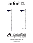
Poles
Sheet 1 of 3
INSTALLATION INSTRUCTIONS
2/15/08
IMPORTANT: READ CAREFULLY BEFORE INSTALLING LUMINAIRE.
RETAIN FOR FUTURE REFERENCE.
!
IMI-484
WARNING
• Make certain power is OFF before starting installation or attempting any maintenance.
• FAILURE TO FOLLOW INSTRUCTIONS MAY RESULT IN SERIOUS INJURY OR DEATH.
General: Upon receipt of pole thoroughly inspect for any freight
damage, which should be brought to the attention of the delivery
carrier. Compare the catalog description listed on the packing slip
with the label on the pole to be sure the correct merchandise has
been received.
Safety: This pole must be grounded in accordance with the
National Electrical Safety Code and applicable local codes and
ordinances. Proper grounding is required to insure personal safety.
Carefully observe grounding procedure under installation section.
This pole is not suitable for Hazardous or Classified Locations. This
product must be installed in accordance with the applicable installation code by a person familiar with the construction and operation
of the product and the hazards involved. Consult a qualified electrician to ensure correct branch circuit conductor.
ANCHOR BOLTS
1. Only bolt and nut kits supplied by Cooper Lighting should be used.
2. Existing anchor bolts or bolt adapters supplied by other than Cooper Lighting should not be used. If they are, Cooper Lighting assumes no
responsibility in case of bolt or adapter failure.
3. Anchor bolt and nuts from other sources should be used only on the advice of a Structural Engineer. Fasteners not suitable for this application can
result in bolt and/or thread failure and consequent collapse of the pole.
CAUTION: Use of nuts from other manufacturers with Cooper Lighting bolts may result in thread failure caused by improper thread fit.
4. In addition to electrical conduit and other equipment necessary to the installation, the foundation bolts should be cast into concrete, in
conformance with the template drawing supplied with the anchor bolts for each particular pole.
CAUTION:
A. Check all templates for dimensional accuracy before using them to locate bolt position in the foundation.
B. Be certain that anchor bolts are properly located to provide the desired directional orientation of the pole.
C. Be certain that the anchor bolts are plumbed vertically, and they extend above the finished surface of the foundation to the extent called for on the
bolt template drawing.
FOUNDATIONS
Since local soil and frost conditions vary widely a Civil Engineer familiar with these conditions should be consulted regarding dimensions and depths of
foundations.
POLE ERECTION AND FIXTURE INSTALLATION
1. All Cooper Lighting steel poles are to be installed using two nuts on each anchor bolt. The first nuts are to be run down on the thread to the top of
the foundation and be checked using a hand level to ensure that the top surfaces of all these nuts are the same height. The pole should then be
installed with its base plate holes over the bolts and the second nut screwed down to a moderate degree of tightness. The pole then should be
checked and adjustments made to ensure that the pole is plumb. When this is satisfactory, tighten the top nuts to the proper torque values as
shown using torque wrench.
Bolt Diameter in Inches
3/4
1
1 3/4
1 1/2
Recommended Ft. lbs. of torque when nuts are not lubricated
105
250
500
870
Fecommended Ft. lbs. of torque when nuts are lubricated
78
190
380
650
2. When the installation is complete and confimred to be correct, the void that appears between the base plate and concrete foundation is to be
filled using a non-shrinking mortar grout. Then shape and finish to a neat appearance.
3. With the exception of the instructions presented on this page, the procedures for fixture installation and pole erection are the responsibility of the
installation contractor
These instructions do not claim to cover all details or variations in the equipment, procedure, or process described, nor to provide directions for meeting every possible
contingency during installation, operation or maintenance. When additional information is desired to satisfy a problem not covered sufficiently for user’s purpose, please
contact your nearest representative.
Customer First Center • 1121 Hwy 74 South • Peachtree City, GA 30269
IMI-484
ACF080468
Poles
Sheet 2 of 3
INSTALLATION INSTRUCTIONS
2/15/08
IMPORTANT: READ CAREFULLY BEFORE INSTALLING FIXTURE.
RETAIN FOR FUTURE REFERENCE.
!
IMI-484
WARNING
• Make certain power is OFF before starting installation or attempting any maintenance.
• FAILURE TO FOLLOW INSTRUCTIONS MAY RESULT IN SERIOUS INJURY OR DEATH.
CAUTIONS:
Cooper Lighting poles have been designed to support only the luminaires and equipment originally intended. miscellaneous items such as pennants
signs and decorations may cause pole failure because of overloading. Addition of these items voids cooper lighting’s warranty. Cooper Lighting will,
however, supply information on total loading EPA on request. Cooper Lighting’s poles are guaranteed only when used in a pole/ luminaire or floodlight
combination. any other application of poles, including application without a luminaire or floodlight, voids Cooper Lighting’s warranty.
GROUNDING:
Poles must be grounded in accordance with requirements in the National Electrical Code and applicable Local Electrical Codes.
VIBRATION:
Many isolated wind conditions exist that can be davasting to poles and luminaires. Although rare, vibrations severe enough to cause damage can
occur in structures of all types influenced by many interacting variables. Vibrations are generally unpredictable. constant winds in the 10-30 mph range
can severely damage certain poles by vibration and there is no single cure that will assure the prevention of all modes of vibration. Many factors may
contribute to the development of a vibration problem. It is not however the result of defective material or workmanship and therefore not covered by
the Cooper Lighting warranty. Vibration dampers that can help alleviate this condition can be supplied by Cooper Lighting either factory installed or for
field installation. Cooper Lighting recommends that vibration dampers be considered when any of the following conditions exist:
1. Poles installed on a bridge structure, overpass, or parking ramp structure.
2. Pole having a fixture epa load of less than 0.5.
3. Camera support poles.
4. Locations that experience prevailing constand winds in the 10 to 30 mph range.
5. Any site that has history of vibration problems.
6. Areas specificed as special wind zones (consult local authorities).
7. Locations near an airport, mountain foothills, great lakes, large open areas of flat ground or any other unique locations that may experience
abnormal wind conditions.
The user’s maintenance program should include observation for excessive vibration and examination for any structural damage or bolt loosening.
Failure to do so could result in structural failure.
Tribute
Single
Dual 2 @ 180
Galleria
Triple 3 @ 90
Quad 4 @ 90
Vision Site
Single
Dual 2 @ 180
Triple 3 @ 90
Quad 4 @ 90
Single
Dual 2 @ 180
Triple 3 @ 90
Quad 4 @ 90
-
-
-
-
-
-
-
-
POLSS4APSA15
100 MPH 100 MPH 100 MPH 100 MPH
POLSS4APSA20
100 MPH 100 MPH 100 MPH
90 MPH
100 MPH
90 MPH
-
-
100 MPH 100 MPH 100 MPH
90 MPH
POLSS4APSA25
100 MPH
90 MPH
80 MPH
80 MPH
90 MPH
-
-
-
100 MPH
90 MPH
80 MPH
80 MPH
POLSS5APSA30
90 MPH
80 MPH
80 MPH
-
80 MPH
-
-
-
90 MPH
80 MPH
80 MPH
-
These instructions do not claim to cover all details or variations in the equipment, procedure, or process described, nor to provide directions for meeting every possible
contingency during installation, operation or maintenance. When additional information is desired to satisfy a problem not covered sufficiently for user’s purpose, please
contact your nearest representative.
Customer First Center • 1121 Hwy 74 South • Peachtree City, GA 30269
IMI-484
ACF080468
Poles
Sheet 3 of 3
INSTALLATION INSTRUCTIONS
2/15/08
IMPORTANT: READ CAREFULLY BEFORE INSTALLING FIXTURE.
RETAIN FOR FUTURE REFERENCE.
!
IMI-484
WARNING
• Make certain power is OFF before starting installation or attempting any maintenance.
• FAILURE TO FOLLOW INSTRUCTIONS MAY RESULT IN SERIOUS INJURY OR DEATH.
ISOTACH WIND MAP
This map has been included in this
catalog in order to aid in the selection
of a pole with regard to its geographic
location. Although a less stringent
25-year mean recurrence map is
sometimes used by other pole
suppliers, it is our belief that the
added measure of assurance offered
in the use of this map deems it more
desirable.
N O T E : This wind map is intended as a
general guideline only. Consult
local engineering standards
to determine the exact wind
loading conditions for your
application.
100 90
70
Seattle
Caribou
Havre
80 Spokane
100
90
Missoula
International Falls
Great Falls
80
70
Portland
Bismark
70
Roseburg
Pocatello
Eureka
70
Sacramento
San Francisco
Lander
90
80
90
Duluth
Fargo
Billings
Boise
Green Bay
Huron
Tonopah
Denver
Kansas City
Milford
Fresno
Grand Junction
Washington D.C.
Richmond
80
90
Norfolk
Lexington
Dodge City
100
Hatteras
Raleigh
70
Los Angeles
Albuquerque
70
Wilmington
100
Atlanta
Charleston
Birmingham
Fort Worth
Special Wind Region
El Paso
100
90
Nome
Alaska
70
Houston
80
Pensacola
New Orleans
90
110
90
70
Anchorage
Miami
70 80
Brownsville
80
100
Juneau
100
100
Tampa
San Antonio
Fairbanks
110
100
90
Jacksonville
70
80
70
80
Jackson
Shreveport
Abilene
100
90
Barrow
110
110
80
Columbia
70
Yuma
(Per ASCE)
Knoxville
Memphis
Little Rock
Phoenix
San Diego
Nashville
Oklahoma City
70
110 Miles
100 Per
90 Hour
Basic
80 Wind
70 Speed
New York
90
Harrisburg
Philadelphia
Pittsburgh
70
90 Columbus
Springfield Indianapolis
Charleston
St. Louis
Las
Vegas
70
Detroit
80
80
Chicago
Des Moines
Lincoln
Hartford
Buffalo
Lansing
Dubuque
Cheyenne
Salt Lake City
Portland
90
Boston
Albany
70
90
80
Reno
Sault Sainte Marie
80
Minneapolis/
St. Paul
Hawaii
Puerto Rico
Kodiak
90
80
95
110
100
WARRANTY AND OBLIGATIONS
THE FOLLOWING WARRANTY IS EXCLUSIVE AND IN LIEU OF ALL OTHER WARRANTIES. WHETHER EXPRESS, IMPLIED OR STATUTORY
INCLUDING, BUT NOT BY WAY OF LIMITATION, ANY WARRANTY OF MERCHANTABILITY OR FITNESS FOR ANY PARTICULAR PURPOSE.
Cooper Lighting warrants to the customer for resale only that Cooper Lighting’s products are free from defects in materials and workmanship. The
obligation of Cooper Lighting under this warranty is expressly limited to repair or replacement without charge, at the sole option of Cooper LIghting of
defective products within a period of one year from the date of shipment of products and only after Cooper Lighting has issued a Return Materials
Authorization to customer for the products.
This warranty does not apply to Cooper Lighting products which have been altered or repaired or which have been subjected to neglect, abuse, misuse or accident (including shipping damages). THIS WARRANTY ALSO DOES NOT APPLY TO PRODUCTS NOT MANUFACTURED BY COOPER
LIGHTING WHICH HAVE BEEN INSTALLED AND USED IN CONJUNCTION WITH COOPER LIGHTING PRODUCTS. This warranty specifically
excludes fatigue or similar failure resulting from induced vibration, harmonic osciliation, or resonance associated with the movement of air currents
around the pole.
LIMITATION OF LIABILITY
IN NO EVENT SHALL COOPER LIGHTING BE LIABLE FOR SPECIAL, INDIRECT, INCIDENTAL, OR CONSEQUENTIAL DAMAGES (REGARDLESS OF
THE FORM OF ACTION, WHETHER IN CONTRACT, STRICT LIABILITY, OR IN TORT INCLUDING NEGLIGENCE) NOR FOR LOST PROFITS; NOR
SHALL THE LIABILITY OF COOPER LIGHTING FOR ANY CLAIMS OR DAMAGE ARISING OUT OF OR CONNECTED WITH THIS AGREEMENT OR
THE MANUFACTURE, SALE, DELIVERY, USE, MAINTENANCE, REPAIR OR MODIFICATION OF THE PRODUCTS, OR SUPPLY OF ANY REPLACEMENT PARTS THEREFORE, EXCEED THE PURCHASE PRICE OF THE PRODUCTS.
THIS LIMITATION OF LIABILITY SHALL APPLY TO ANY LIABILITY FOR DEFAULT UNDER OR IN CONNECTION WITH THE PRODUCTS, PARTS, OR
SERVICES DELIVERED HEREUNDER WHETHER BASED ON WARRANTY. FAILURE OF OR DELAY IN DELIVERY, OR OTHERWISE NO LABOR
CHARGES WILL BE ACCEPTED WITHOUT PRIOR WRITTEN APPROVAL OF COOPER LIGHTING. THIS CLAUSE SHALL SURVIVE FAILURE OF AN
EXCLUSIVE REMEDY.
These instructions do not claim to cover all details or variations in the equipment, procedure, or process described, nor to provide directions for meeting every possible
contingency during installation, operation or maintenance. When additional information is desired to satisfy a problem not covered sufficiently for user’s purpose, please
contact your nearest representative.
Customer First Center • 1121 Hwy 74 South • Peachtree City, GA 30269
IMI-484
ACF080468