1
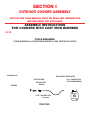
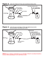
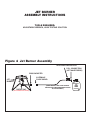
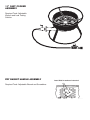
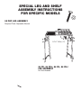
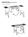
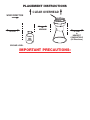
OUTDOOR COOKERS
ASSEMBLY INSTRUCTIONS
AND
USE AND CARE MANUAL
READ OPERATING INSTRUCTIONS BEFORE USING YOUR GRILL.
RETAIN THESE INSTRUCTIONS FOR FUTURE REFERENCE.
METAL FUSION, INC.
712 St. George Avenue.
Jefferson, LA 70121
For Questions and Information
Call Us Toll Free at
1-800-783-3885
8:00 AM to 3:30 P.M. CST • Monday through Friday
(504) 736-0201
WARNING
FAILURE TO FOLLOW THESE INSTRUCTIONS
AND WARNINGS COULD RESULT IN
PROPERTY DAMAGE, PERSONAL INJURY OR DEATH.
FOR YOUR SAFETY
If you smell gas:
1. Shut off gas to the appliance.
2.
Extinguish any open flame.
3.
If odor continues, immediately call your gas supplier or your fire
department.
IMPORTANT SAFETY INFORMATION
1.
Do not store or use gasoline or other flammable vapors and liquids in
the vicinity of this or any other appliance.
2.
When cooking with oil/grease, do not exceed 350˚ F (177 C). Do not
store or use extra cooking oil in the vicinity of this or any other
appliance.
3.
Remember: An LP cylinder not connected for use shall not be stored in
the vicinity of this or any other appliance.
WARNING
FAILURE TO FOLLOW THESE INSTRUCTIONS
AND WARNINGS COULD RESULT IN PROPERTY
DAMAGE, PERSONAL INJURY OR DEATH.
2
WARNING
READ AND UNDERSTAND BEFORE USING THIS PRODUCT
1)
Use the products only outdoors, and only on a noncombustible surface
such as brick, concrete, or dirt. NOT SUITABLE are surfaces such as
wood, asphalt or plastic which may burn, blister, or melt.
Do not use under any overhang or roof and keep a minimum of 10 feet
of clearance on all sides of the cooker.
DO NOT LEAVE UNATTENDED WHILE COOKER
IS IN USE OR IS STILL HOT (ABOVE 100˚F).
2)
Leak test gas connections before use. (See Use and Care Section for
complete Leak Test Instructions.)
3)
Cooking with oil is not similar to any other cooking method. Cooking oil
is very combustible at high temperatures and special precautions must
be taken to avoid a dangerous grease fire.
Never leave cooker unattended. If a fire occurs, use a Type
B.C. dry chemical fire extinguisher to entinguish the flames.
Turn off the gas at the supply cylinder. Do not use water to
attempt to extinguish a grease fire.
If the fire cannot be extinguished, call your Fire Department.
4)
Wear shoes while cooking and keep hair and clothing from coming into
contact with the cooker while in use, or still hot. Always wear cooking
mitts when handling the cooker, cooking utensils and accessories.
5)
Never move the cooker while in use or still hot (above 100˚F).
6)
King Kooker® products are not designed for use as space heaters, and
must never be used indoors for heating or cooking.
7)
Follow lighting procedure in Use and Care section, using a fireplace
match or gas appliance butane lighter.
3
8)
King Kooker ® products are designed for use with propane gas, with the
regulator supplied with the product, and must never be used with
natural gas. Accessories not recommended by Metal Fusion, Inc., must
not be used with King Kooker® appliances.
9)
See Use and Care section for LP Gas Cylinder information.
10) Consumption of alcohol and drugs will impair the consumer’s ability to
safely assemble and use these products, and must be avoided when
the cookers are in use and when the cooking oil is still hot (above 100˚ F).
11) An outdoor cooker is to be used by adults only. Keep children and pets
away from the appliance at all times.
12) In the event of rain, while cooking with oil/grease, cover the cooking
vessel immediately. Shut appliance burners and gas supply OFF. Do
not attempt to move appliance or cooking vessel.
13) Use King Kooker® appliances only in accordance with state and local
ordinances.
14) See the Use and Care section for Placement Instructions.
WARNING
FAILURE TO COMPLY WITH THESE WARNINGS AND
INSTRUCTIONS CAN RESULT IN PROPERTY DAMAGE,
PERSONAL INJURY AND DEATH.
4
READ AND UNDERSTAND ALL INSTRUCTIONS BEFORE
USING YOUR KING KOOKER® PRODUCT
TABLE OF CONTENTS
Warnings. . . . . . . . . . . . . . . . . . . . . . . . . . . . . . . . . . . . . . . . . . . . . . . . . . . . . . . . . . . . . . 2-4
Table of Contents. . . . . . . . . . . . . . . . . . . . . . . . . . . . . . . . . . . . . . . . . . . . . . . . . . . . . . . . 5
Warranty . . . . . . . . . . . . . . . . . . . . . . . . . . . . . . . . . . . . . . . . . . . . . . . . . . . . . . . . . . . . . . . 6
Owners Registration. . . . . . . . . . . . . . . . . . . . . . . . . . . . . . . . . . . . . . . . . . . . . . . . . . . . 7-8
Section I - King Kooker ® Outdoor Cooker Assembly . . . . . . . . . . . . . . . . . . . . . . . . . 9
Cast Iron Cooker Assembly Instructions . . . . . . . . . . . . . . . . . . . . . . . . . . . . . . . . . . . 9-10
Jet Burner Assembly Instructions . . . . . . . . . . . . . . . . . . . . . . . . . . . . . . . . . . . . . . . . . . 11
Camp Stove Assembly Instructions . . . . . . . . . . . . . . . . . . . . . . . . . . . . . . . . . . . . . . . . 12
101 PK Assembly Instructions . . . . . . . . . . . . . . . . . . . . . . . . . . . . . . . . . . . . . . . . . . . . 13
11” Cast Cooker Assembly. . . . . . . . . . . . . . . . . . . . . . . . . . . . . . . . . . . . . . . . . . . . . . . 14
Fry Basket Handle Assembly . . . . . . . . . . . . . . . . . . . . . . . . . . . . . . . . . . . . . . . . . . . . . 14
Special Leg and Shelf Assembly Instructions For Specific Models:
95 PKP Leg Assembly . . . . . . . . . . . . . . . . . . . . . . . . . . . . . . . . . . . . . . . . . . . . . . 15
84 PK, 84 PKJ, 86 PK, 86 PKJ Leg Assembly . . . . . . . . . . . . . . . . . . . . . . . . . . . . 15
Camp Stove Leg Assembly . . . . . . . . . . . . . . . . . . . . . . . . . . . . . . . . . . . . . . . . . . 16
Camp Stove Shelf Assembly for CS 2L WS and CS 3L WS . . . . . . . . . . . . . . . . . . 16
CS 4L Extension Legs Assembly . . . . . . . . . . . . . . . . . . . . . . . . . . . . . . . . . . . . . . 16
CS 5 Leg Assembly . . . . . . . . . . . . . . . . . . . . . . . . . . . . . . . . . . . . . . . . . . . . . . . . 17
CS 8 Leg Assembly . . . . . . . . . . . . . . . . . . . . . . . . . . . . . . . . . . . . . . . . . . . . . . . . 17
106 PK & 106 PKPT Extension Leg Assembly . . . . . . . . . . . . . . . . . . . . . . . . . . . . 18
Model #TWT Worktable Assembly . . . . . . . . . . . . . . . . . . . . . . . . . . . . . . . . . . . . . 19
Section II - Use and Care of King Kooker® Outdoor Cookers and Accessories . . 20
Connection Instructions . . . . . . . . . . . . . . . . . . . . . . . . . . . . . . . . . . . . . . . . . . . . . . . . . 20
Leak Test Instructions . . . . . . . . . . . . . . . . . . . . . . . . . . . . . . . . . . . . . . . . . . . . . . . . . . 20
Placement Instructions . . . . . . . . . . . . . . . . . . . . . . . . . . . . . . . . . . . . . . . . . . . . . . . . . 21
LP Gas Cylinder Information . . . . . . . . . . . . . . . . . . . . . . . . . . . . . . . . . . . . . . . . . . . . . 21
Lighting Instructions . . . . . . . . . . . . . . . . . . . . . . . . . . . . . . . . . . . . . . . . . . . . . . . . . . . 22
Frying Precautions and the Use of a Deep Fry Thermometer . . . . . . . . . . . . . . . . . . . . . 22
Turning Off and Storing the Cooker after Use . . . . . . . . . . . . . . . . . . . . . . . . . . . . . . . . 23
Caring For Aluminum and Cast Iron Cookware . . . . . . . . . . . . . . . . . . . . . . . . . . . . . . . 23
Section III - Cooking Specialties . . . . . . . . . . . . . . . . . . . . . . . . . . . . . . . . . . . . . . . . . . 24
Deep Fried Turkey Instructions . . . . . . . . . . . . . . . . . . . . . . . . . . . . . . . . . . . . . . . . . 24-25
Injecting Techniques . . . . . . . . . . . . . . . . . . . . . . . . . . . . . . . . . . . . . . . . . . . . . . . . . . . 26
King Kooker® Steamer Package Instructions . . . . . . . . . . . . . . . . . . . . . . . . . . . . . . . . . 27
Section IV - Recipes . . . . . . . . . . . . . . . . . . . . . . . . . . . . . . . . . . . . . . . . . . . . . . . . . . . . 28
Boiled Seafood . . . . . . . . . . . . . . . . . . . . . . . . . . . . . . . . . . . . . . . . . . . . . . . . . . . . . . . 28
Blackened Fish . . . . . . . . . . . . . . . . . . . . . . . . . . . . . . . . . . . . . . . . . . . . . . . . . . . . . . . 28
Barbecued Shrimp. . . . . . . . . . . . . . . . . . . . . . . . . . . . . . . . . . . . . . . . . . . . . . . . . . . . . 29
King Kooker® Beans . . . . . . . . . . . . . . . . . . . . . . . . . . . . . . . . . . . . . . . . . . . . . . . . . . . 29
King Kooker® 12 Qt. Dutch Oven Jambalaya . . . . . . . . . . . . . . . . . . . . . . . . . . . . . . . . . 29
Fried Seafood . . . . . . . . . . . . . . . . . . . . . . . . . . . . . . . . . . . . . . . . . . . . . . . . . . . . . . . . 29
Deep Fried Turkey. . . . . . . . . . . . . . . . . . . . . . . . . . . . . . . . . . . . . . . . . . . . . . . . . . . . . 30
Fried Chicken . . . . . . . . . . . . . . . . . . . . . . . . . . . . . . . . . . . . . . . . . . . . . . . . . . . . . . . . 30
Fried Onion Rings . . . . . . . . . . . . . . . . . . . . . . . . . . . . . . . . . . . . . . . . . . . . . . . . . . . . . 30
Fried Mushrooms . . . . . . . . . . . . . . . . . . . . . . . . . . . . . . . . . . . . . . . . . . . . . . . . . . . . . 30
Deep Fried Boston Butt . . . . . . . . . . . . . . . . . . . . . . . . . . . . . . . . . . . . . . . . . . . . . . . . . 31
King Kooker® Wings . . . . . . . . . . . . . . . . . . . . . . . . . . . . . . . . . . . . . . . . . . . . . . . . . . . 31
Steamed Clams and Mussels . . . . . . . . . . . . . . . . . . . . . . . . . . . . . . . . . . . . . . . . . . . . 31
Steamed Crab, Shrimp, and Lobster . . . . . . . . . . . . . . . . . . . . . . . . . . . . . . . . . . . . . . . 31
5
METAL FUSION, INC.
LIMITED ONE-YEAR WARRANTY
WHAT THIS WARRANTY COVERS
This warranty covers all components of this outdoor cooker to be free from defects in materials and
workmanship, with the exceptions stated below.
HOW LONG COVERAGE LASTS
This warranty runs for one year from the date of purchase.
WHAT IS NOT COVERED
This warranty does not cover the following:
Incidental and Consequential Damages. This warranty does not cover incidental and
consequential damages arising in any way out of the use of this outdoor cooker. The liability of
Metal Fusion, Inc. is, in any event, limited to the amount of the original purchase price of this
outdoor cooker, and remains in force only as long as the product remains in its original, as-built
configuration. Some states do not allow the exclusion or limitation of incidental or consequential
damages, so the above limitation or exclusion may not apply to you.
Neglectful Operation. This warranty does not cover any loss or damage arising in any
way due to the negligent operation of this outdoor cooker.
Altered, Repaired or Misused Equipment. This warranty does not cover any loss or
damage arising in any way out of the use of this outdoor cooker when it has been altered, repaired
by persons other than Metal Fusion, Inc., or when it has been abused or misused, or when it has
been used other than in accordance with the manufacturer’s operating instructions, including,
without limitation, any damage to the consumer’s pots because they were placed on a lit cooker
while the pot is empty.
Other Assumed Responsibilities. Unless otherwise provided by law, this warranty does
not cover any responsibility or liability arising in any way out of the use of this product where that
responsibility or liability was purportedly assumed by any other person or agent.
Paint, Discoloration and Rust. This warranty does not cover the paint on the outdoor
cooker, as in a normal use of the outdoor cooker, the paint will be burned off. Nor does this
warranty cover discoloration or rust as these occurrences are part of the cooker’s normal wear and
tear.
WHAT METAL FUSION, INC. WILL DO
Metal Fusion, Inc. will repair or replace any outdoor cooker that proves to be defective in materials or
workmanship. In the event repair is not possible or economically feasible, Metal Fusion, Inc. will
replace your outdoor cooker with an identical or substantially equivalent outdoor cooker. Metal Fusion,
Inc. will perform this service at no charge to you, except for the actual cost of shipping and handling
the outdoor cooker or replacement parts.
HOW TO GET SERVICE
In the event you have a problem or malfunction with your outdoor cooker, simply call Metal Fusion, Inc.
at (800) 783-3885.
HOW STATE LAW APPLIES
This warranty gives you specific rights, and you may have other rights which vary from state to state.
6
OWNER’S REGISTRATION
®
Dear Customer,
Thank you for purchasing a King Kooker®! Please take a moment to fill out
your registration form and return it to us. We are always happy to hear
suggestions and comments from our customers about our products. Completion of
this registration allows us to contact you if the need arises.
Name: __________________________________________________________
Address: ________________________________________________________
________________________________________________________________
________________________________________________________________
________________________________________________________________
Model# __________________________________________________________
Date of Purchase __________________________________________________
Place of Purchase __________________________________________________
Price Paid ________________________________________________________
Was this a gift _____ or did you _____ purchase it yourself?
________________________________________________________________
________________________________________________________________
Comments:
________________________________________________________________
________________________________________________________________
✄
A SATISFIED CUSTOMER IS OUR MAIN GOAL. If you have any questions or
problems, please call us at 1-800-783-3885 before returning the product to the
point of purchase.
THANK YOU,
ENJOY YOUR COOKING EXPERIENCE.
7
TAPE HERE
FOLD
________________________
________________________
________________________
Place
Stamp
Here
METAL FUSION, INC.
712 St. George Avenue
Jefferson, LA 70121
FOLD
8
SECTION I
OUTDOOR COOKER ASSEMBLY
THE USE AND CARE MANUAL MUST BE READ AND UNDERSTOOD
BEFORE USING THE APPLIANCE
ASSEMBLY INSTRUCTIONS
FOR COOKERS WITH CAST IRON BURNERS
NOTE: The following are general instructions for 5-6” Cast Burners. If your cooker is a 101 PK or has
an 11” Cast Burners, please refer to the special assembly instructions which have been written
especially for these units.
TOOLS REQUIRED:
TORQUE WRENCH or ADJUSTABLE WRENCH, LEAK TESTING SOLUTION
1.
Before assembling, check that all cooker components are included in the shipping carton. Identify
these cooker parts from the assembly drawing. Accessories such as pots may vary according to
model. Check the list of accessories on your cooker box.
2.
Read assembly instructions, and understand sequence of assembly, before commencing to
assemble your cooker.
3.
NOTE: The hose to burner connection will be one of the following:
Figure 1) Hose with male fitting and adjustable regulator.
Figure 2) Hose with female fitting and adjustable regulator.
Figure 3) Hose with male or female fitting and needle valve with non-adjustable pressure
regulator.
COOKING POT
ADJUSTABLE REGULATOR
VENTURI TUBE
AIR SHUTTER
BURNER
P.O.L. CONNECTION
(LEFT HAND THREAD)
SPRING
TYPE 1 CONNECTION
(1/8 mnpt)
Cast Iron
9
LP
GAS
TANK
Figure 2
HOSE WITH FEMALE FITTING AND ADJUSTABLE REGULATOR.
COOKING POT
ADJUSTABLE REGULATOR
VENTURI TUBE
AIR SHUTTER
P.O.L. CONNECTION
(LEFT HAND THREAD)
SPRING
HALF UNION
O
N
BURNER
LP
GAS
TANK
3/8 FEMALE
FLARE SWIVEL
The air shutter, spring and half union as pictured should already be assembled to the casting.
Figure 2
Check that fitting is tightened to the venturi tube and that the elbow points downward. If loose,
wrench tighten the 3/8 female flare swivel to the brass half union.
Figure 3
HOSE WITH MALE OR FEMALE FITTING AND NEEDLE VALVE WITH
NON-ADJUSTABLE PRESSURE REGULATOR.
COOKING POT
NEEDLE VALVE
NON-ADJUSTABLE
PRESSURE REGULATOR
VENTURI TUBE
AIR SHUTTER
SPRING
P.O.L. CONNECTION
(LEFT HAND THREAD)
BURNER
Type1 Connection
(1/8 mnpt)
LP
GAS
TANK
Figure 3 pressure regulator as above with a Type 1
If your cooker has a needle valve and a non-adjustable
connection, refer to directions in Figure 1.
If your cooker has a needle valve and a non-adjustable pressure regulator as above, but a Type 2
connection, refer to the directions for Figure 2.
4.
Go to the Use and Care Section for further instructions.
NOTE: If your cooker has attachable legs or work table, follow the assembly instructions
for these before proceding to the Use and Care section.
10
JET BURNER
ASSEMBLY INSTRUCTIONS
TOOLS REQUIRED:
ADJUSTABLE WRENCH, LEAK TESTING SOLUTION
1.
Before assembling, check that all cooker components are included in the shipping carton, as per
Figure 4.
2.
Read and understand assembly instructions.
Figure 4 Jet Burner Assembly
ADJUSTABLE REGULATOR
P.O.L. CONNECTION
(LEFT HAND THREAD)
BRASS ADAPTER
3/8 FEMALE
FLARE SWIVEL
JET
BURNER
ORIFICE CAP
O
N
(SOME MODELS MAY HAVE NEEDLE
VALVES AND PRESSURE REGULATORS
AS PER FIGURE 3)
LP
GAS
TANK
(DO NOT REMOVE THIS FITTING)
Tighten the 3/8” female flare swivel to the brass adapter.
The hose to burner (brass adapter) connection must be tightened and leak tested. See leak test
instructions before use.
Go to the Use and Care Section of this manual for further instructions.
11
CAMP STOVE
ASSEMBLY INSTRUCTIONS
TOOLS REQUIRED:
ADJUSTABLE WRENCH
LEAK TESTING SOLUTION
1.
Procedures for assembly of all Camp
Stoves is the same, only the number of
burners vary.
2
Place burner frame on side so that the
casting ends are turned upward.
CASTING
VENTURI
TUBES
3.
Loosen nuts on bottoms of castings and
remove all castings from frame.
AIR SHUTTERS
SPRINGS
4.
Remove the air shutter and spring from
the bag and place the air shutter over the
end of the casting venturi tube. Hold the
wide end of the spring against the air
shutter and insert one male threaded end
of the manifold into the end of the venturi
on the casting.
MANIFOLD
REGULATOR
5.
Screw casting onto manifold.
6.
Repeat steps 4 and 5 with each casting until manifold is complete.
7.
Reassemble castings to frame by retightening nuts with manifold attached to castings.
8.
Refer to the Instructions for Camp Stove Legs and Shelf Assembly at this time if using legs or
shelves.
9.
Refer to the Use and Care Section of this manual for further instructions.
12
101 PK ASSEMBLY INSTRUCTIONS
WARNING
The following warnings are to be followed when using the 101 PK
in addition to all other warnings listed in this manual. Observe these safety
precautions when using a 14.1 or 16.4 oz. portable propane cylinder.
1.
Always inspect appliance, propane cylinder and propane connections for damage, dirt or
debris before attaching propane cylinder.
2.
Protect propane cylinder from excessive heat.
3.
Screw propane cylinder into appliance and hand tighten only. Do not cross thread.
4.
When transporting or storing appliance, always disconnect propane cylinder.
5.
Always use appliance in upright position.
6.
Use only 14.1 oz. or 16.4 oz. propane fuel cylinder as approved by U.S. Department of
Transportation (D.O.T.)
ASSEMBLY:
1.
Turn the control valve clockwise to the OFF Position. Make sure knob pops up for OFF.
2.
Attach valve adapter assembly to propane cylinder and hand tighten. Do not cross thread.
3.
Refer to the Use and Care Section of this manual for further directions.
13
11” CAST COOKER
ASSEMBLY
Required Tools: Adjustable
Wrench and Leak Testing
Solution
1.
Wrench tighten the brass
control valve to the 11”
casting.
2.
Wrench tighten the brass
3/8” flare swivel fitting to
the brass control valve.
3.
Tighten
left
handed
threads on POL nut hand
tight to the cylinder and
then secure with a wrench.
Caution: Do not turn
regulator or nipple.
O
N
4.
The hose to burner (brass adapter) connection must be tightened and leak tested. See leak test
instructions before use.
5.
Go to the Use and Care Section of this manual for further instructions.
FRY BASKET HANDLE ASSEMBLY
Insert Bolts in marks as instructed
Required Tools: Adjustable Wrench and Screwdriver
1.
Attach handle by inserting bolts (round head to
inside of pan) into holes indicated in black. Also
insert bolt (round head to inside of pan) into hole
indicated with an “X”. Apply nuts and tighten.
(This bolt helps hold the basket away from pot
when hooking it on the side of the pot to drain oil
from food.)
14
SPECIAL LEG AND SHELF
ASSEMBLY INSTRUCTIONS
FOR SPECIFIC MODELS
95 PKP LEG ASSEMBLY
/16
Required Tools: Adjustable Wrench
"X
1.
Match the holes in each leg with the
corresponding holes in the cooker.
2.
Slide one 1/4” x 1” bolt through each of the
twelve holes. These should be directed
inward as in the illustration so that the nuts
will be on the inside of the assembly.
3.
Screw 1/4” nut onto each bolt and wrench
tighten. Make certain every bolt and nut
assembly is completely tightened so the unit
will stand sturdily, with no sway, when the
unit is upright.
1/4"x1" Bolts (12)
84 PK, 84 PKJ, 86 PK, 86 PKJ
LEG ASSEMBLY
No Tools Needed
1.
Place burner unit upside down on the floor.
2.
Put one leg, notched end down, onto a half inch
round bar brace where it connects to the outer ring.
Slide the slot onto the bottom ring on the burner.
Repeat for each of the other two legs.
3.
Slide the carriage bolts through the center
bracket. Slide a bolt through a hole in each leg. Screw
the wing nut to the ends of the carriage bolts and
tighten completely.
4.
Turn burner right side up and place on the level
surface for cooking.
15
CAMP STOVE LEG ASSEMBLY
Required Tools: Adjustable Wrench
1.
Match the holes in each leg with corresponding holes in
cooker.
2.
Slide 1/4” x 1” bolt through each of the twelve holes.
These should be directed inward as in the illustration so
that the nuts will be on the inside of the assembly.
3.
1/4"x1" bolts (12)
Screw 1/4” nut onto each bolt and wrench tighten.
Make certain every bolt and nut assembly is completely
tightened so the unit will stand sturdily with no sway
when the unit is upright.
CAMP STOVE SHELF ASSEMBLY FOR CS 2L WS AND CS 3L WS
Required Tools: Adjustable Wrench
1. Slip shelf lip under angle
iron. (A)
O
(A)
N
(A)
(B)
(B)
2. Install 1/4” x 1” bolts
through holes. Wrench tighten
1/4” nut to bolt. (B)
(B)
For Outdoor Use Only
(B)
CS 4L EXTENSION LEGS ASSEMBLY INSTRUCTIONS
Required Tools: Adjustable Wrench
1.
Match the holes in each leg with the
corresponding holes in the cooker as
pictured at right.
2.
Slide one 1/4” x 1 “ bolt through each of
the three holes in each extension leg and
cooker leg. These should be directed
inward so that the nuts will be on the
inside of the assembly.
3.
Screw 1/4” nut onto each bolt and wrench
tighten. Make certain that every bolt and
nut assembly is completely tightened so
that the unit will stand sturdily with no
sway when the unit is upright.
16
CS 5 LEG ASSEMBLY
Required Tools: Adjustable Wrench
1.
Match the holes in each leg with corresponding holes in cooker.
2.
Slide 1/4” x 1” bolt through
each of the twelve holes.
These should be directed
inward as in the illustration so
that the nuts will be on the
inside of the assembly.
3.
Screw 1/4” nut onto each bolt
and wrench tighten. Make
certain every bolt and nut
assembly
is
completely
tightened so the unit will stand
sturdily with no sway when
the unit is upright.
1/4"x1"
Bolts (12)
CS 8 LEG ASSEMBLY
No Tools Required
1.
This cooker has four legs with crossbars and two stabilizer bars.
2.
Flip the legs into the standing
position.
3.
Hook each stabilizer bar over the
crossbar on the leg opposite it. The hook
on the end of the bar must be pressed
down around the crossbar so that the leg
is locked into position. Always recheck
that both hooks are in place before
lighting the cooker or placing cooking
equipment on top of the cooker.
17
106 PK AND 106 PKPT
EXTENSION LEGS ASSEMBLY INSTRUCTIONS
Required Tools: Adjustable Wrench
1.
Match the holes in each leg with corresponding holes in cooker.
2.
Slide one 1/4” x 1” bolt through each of the three holes in each extension leg and cooker leg.
These should be directed inward so that the nuts will be on the inside of the assembly.
3.
Screw 1/4” nut onto each bolt and wrench tighten. Make certain every bolt and nut assembly is
completely tightened so the unit will stand sturdily with no sway when the unit is upright.
4.
Hang the shelves on the sides
of the cooker, as per the
illustration, using the clips which
are welded to the shelves.
18
MODEL #TWT WORKTABLE ASSEMBLY
Required Tools: Adjustable Wrench
This unit is designed to be used as a worktable for the preparation of turkeys for frying and for
draining afterwards. It is not intended for any other use. It is to be used only with Deep Fryer
Turkey Packages. This worktable assembly is NOT for use with Model #3018.
1.
Stand worktable and cooker
side by side, as in the
illustration, on a level, sturdy,
non-combustible surface.
2.
Hold the side of the worktable
with the brackets next to the
cooker. Line up one pair of the
holes in a bracket so that one
hole is above the cooker ring
and one is below. Choose to
use the pair of holes which will
allow the worktable to be level.
Some models of cookers will
use the top sets of holes in the
brackets, while some models
work best with the lower sets
of holes. Make sure that the
work surface will be flat when
assembly is complete.
3.
Slide the U-bolts around the
top ring of the cooker and
through the holes in one of the
brackets. Do the same for the
other bracket.
4.
Screw one of the 1/4” wing nuts onto each end of a threaded U-bolt and wrench tighten. Make
certain that each U-bolt and wing nut assembly is tightened so that the unit will stand sturdily with
no sway when the unit is attached.
19
SECTION II
USE AND CARE
CONNECTION INSTRUCTIONS
1.
Check that your 20 lb. LP gas cylinder is not over-filled. The maximum weight of a properly filled
cylinder is approximately 38 lbs.
2.
Verify that the cylinder valve has the proper connection for a P.O.L. appliance fitting.
3.
Attach the regulator to the cylinder by the lefthand threaded P.O.L. fitting. The P.O.L. nut must be
wrench tightened with the regulator positioned upright.
LEAK TEST
4.
Before lighting the appliance, a thorough leak test must be satisfactorily completed using a
non-ammonia soapy water solution (50% non-ammonia soap and 50% water). This is to be
applied with a small brush to all gas joints after the cylinder valve is opened (no more than 1/2
turn). If bubbles are seen, indicating a leak, turn off the cylinder and tighten the leaking
connection until a further leak test shows no leaks.
If a repair cannot be made, call your local dealer or Metal Fusion, Inc., (800) 783-3885, for
assistance.
DO NOT USE UNTIL REPAIRS ARE MADE
5.
Before lighting the cooker, check that the venturi tube is free of obstruction and is properly located
over the orifice. Both situations must be corrected, if necessary, before lighting to prevent
flashback.
20
PLACEMENT INSTRUCTIONS
CLEAR OVERHEAD
WIND DIRECTION
24"
MINIMUM
10 FEET
LP
GAS
TANK
COOKER
10 FEET
to
NEAREST
COMBUSTIBLE
(All Directions)
GROUND LEVEL
IMPORTANT PRECAUTIONS:
1.
Appliance must be in open area with at least 10 feet of space on all sides.
2.
There must be no combustibles or roof overhead.
3.
There must be at least 2 feet of space between LP gas tank and cooker.
4.
The LP gas tank and cooker must be located so that any wind is blowing the heat of the cooker
away from the gas tank. This also helps fire prevention by blowing the flames of a grease fire
away from the gas tank.
5.
Center the pot over the burner on the cooker. Use caution when choosing the size of the pot to
use on your cooker to avoid hazards. For example, a too large pot on a tall cooker runs the risk
of tipping or being too tall to stir or watch the food without being burned. Use large pots only on
short cookers.
21
LIGHTING INSTRUCTIONS
WARNING
THE COOKER MUST NOT BE LIT UNTIL THE PRECEDING
PLACEMENT INSTRUCTIONS HAVE BEEN COMPLETELY FOLLOWED.
FOR MODELS WITH ADJUSTABLE REGULATORS
1.
Make certain that the regulator control is turned down to OFF.
2.
Open cylinder control valve.
3.
Hold a lighted long kitchen match or burning butane lighter over the burner and turn the regulator
control until ignition occurs. When lighting the stove, if ignition does not occur in 3 to 5 seconds,
turn the burner control(s) off. Wait 5 minutes. Repeat procedure.
4.
Turning the control clockwise increases the gas pressure to the burner and hence the flame size.
5.
Burner Air Shutter Adjustment: Rotate the air shutter from most closed position to obtain a blue
flame. Note: Opening the shutter too much will cause the flame to “Lift” off the burner.
FOR MODELS WITH NEEDLE VALVE CONTROLS
1.
With the needle valve turned down to OFF, open the cylinder valve.
2.
Hold a lighted long kitchen match or burning butane lighter over the burner and turn the regulator
control until ignition occurs. When lighting the stove, if ignition does not occur in 3 to 5 seconds,
turn the burner control(s) off. Wait 5 minutes. Repeat procedure.
3.
Turning the control counter clockwise increases the gas flow and flame size at the burner.
4.
Burner Air Shutter Adjustment: Rotate the air shutter from most closed position to obtain a blue
flame. Note: Opening the shutter too much will cause the flame to “Lift” off the burner.
WARNING
NEVER PUT HANDS OR FACE DIRECTLY OVER BURNER WHILE LIGHTING.
FRYING PRECAUTIONS AND THE USE OF A DEEP FRY THERMOMETER
Never cover the pot when cooking with oil. Never fill a fry pan more than half way with oil to prevent
overboil. Frozen food or food with excessive amounts of water should not be placed in hot oil. This can
cause the splatter of oil, dangerous burns and fires. Make sure that the food is dry. Never put an empty
aluminum pot over an open flame.
Always use a Deep Fry Thermometer to monitor the tempertature of the grease when deep frying with
an outdoor cooker. Hang the thermometer on the inside of the pot with the probe immersed in the oil.
NEVER LEAVE THE COOKER UNATTENDED. Once the fire has been lit, watch that the temperature
on the thermometer does not go over 350˚F. Oil can ignite at higher temperatures. Most King Kooker®
thermometers have a Red Zone above 350˚F to signify Danger. Never allow the temperature to
exceed 350˚F. If the temperature goes above 350˚F or if oil begins to smoke, immediately reduce the
flame by turning the adjustable regulator/needle valve adjustment.
22
TURNING OFF AND STORING
THE COOKER AFTER USE
After each use turn OFF the King Kooker® at the regulator/needle valve first, then at the gas cylinder
valve. Check to make sure there is no flame and all valves are off before leaving the cooker.
WARNING
NEVER MOVE THE COOKER WHILE IN USE OR STILL HOT (ABOVE 100˚F).
Storage of this cooker indoors is permissible only if the cylinder is disconnected and removed from the
cooker.
Do not use or store cylinder in a building, garage or enclosed area. Read and follow cylinder
manufacturer’s instructions.
TIPS FOR CARING FOR ALUMINUM FRY PANS AND
BOILING POTS
It is not necessary to season aluminum pots before cooking with them. Wash with a liquid dish washing
detergent and towel dry.
After cooking, wash aluminum pots and fry pans in hot, sudsy detergent. If grease or black soot has
cooked to the outside of the pot while cooking with your outdoor cooker, scrub the outside of the pot
with a steel wool scouring pad.
DO NOT SPRAY OVEN CLEANER ON ALUMINUM POTS TO REMOVE GREASE OR SOOT. OVEN
CLEANER WILL CAUSE THE FINISH TO BECOME DULL.
If food remains stuck in the pan after cooking, add hot water and let soak. Then scrub the pan with
soap and steel wool to loosen the food.
If hard water causes darkening or the interior of your pot, fill to the level of the darkened area with a
water and cream of tartar or vinegar solution (mixed with the concentration of three cups of water to
one tablespoon cream of tartar, or vinegar). Boil five to ten minutes.
Never place an empty aluminum or stainless steel pot on a lit cooker. A hole will be burned in the
bottom of the pot. Discoloration, scratching, and dimpling which may occur with use of pots on outdoor
cookers does not affect the performance of the pot.
SEASONING & CARE OF CAST IRON COOKWARE
New Cast Iron Pots are coated with paraffin to prevent rusting. Before using for the first time, wash
with mild soapy water, rinse, and dry thoroughly. Never use abrasive detergents. Grease the entire
surface of the cookware with a thin coating of solid vegetable shortening. Do not use salted fat
(margarine or butter). Heat for 30-60 minutes in oven at 300-350˚F. Remove from oven, pour out
excess grease, and wipe with a paper towel. This completes the seasoning process. Each time the
cast iron is used, coat the entire surface with a thin coat of solid vegetable shortening, wipe with a
paper towel, and store.
23
KING GRILLEDINE, KING KOOKER, the KING KOOKER logo, THE KING,
THE KING OF OUTDOOR COOKING, and MR. OUTDOORS are trademarks of Metal Fusion, Inc.,
712 St. George Avenue, Jefferson, LA 70121
Rev. 8/2000