1
User’s Manual
Line Thermal Printer
Model : iDP-3210
Rev.
Issued
Japan CBM Corporation
Information Systems Div.
iDP-3210 User’s Manual
1996.08.02(10-DCL)15
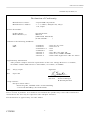
Declaration of Conformity
Manufacturer's Name :
Manufacturer's Address
: Japan CBM Corporation
: 1-1-7, Okubo, Shinjuku-ku, Tokyo
169, Japan
Declare the Product
Product Name
Model Number (s)
Thermal Printer
iDP3210
(iDP3210R, iDP3210P)
(S.NO.9690001 )
Conform to the following Standards
LVD
EMC
:
:
:
:
:
:
:
EN60950
EN55022
EN61000-3-2
EN50082-1
IEC801-2
IEC801-3
IEC801-4
:1992+A1+A2:1993
:1994 Class A
:1995
:1992
:1991 4KV CD, 8KV AD
:1984 3V/m, 27MHz-500MHz
:1988 0.5KV Signal Line 1KV AC mains
Supplementary Information
"The product complies with the requirements of the Low Voltage Directive 73/23/EEC,
93/68/EEC and the EMC Directive 89/336EEC, 92/31/EEC, 93/68EEC"
Place
Tokyo, Japan
Date
Sept.1996
Signature
Full Name : Koji Tanabe
Position : General Manager
R & D Department
Europe Contact :
Europe Liaison Office
Kuruisweg 805, Holland Office Center Building
3-2132 NG Hoofddorp, the Netherlands
Warning
This is a Class A products. In a domestic environment this product may cause radio interference
in which case the user may be required to take adequate measures.
This declaration is applied only for 230V model.
CITIZEN
2
iDP-3210 User’s Manual
IMPORTANT SAFETY INSTRUCTIONS
l
l
l
Read all of these instructions and save them for later reference.
Follow all warnings and instructions marked on the product.
Unplug this product from the wall outlet before cleaning. Do not use liquid or aerosol
cleaners. Use a damp cloth for cleaning.
l Do not use this product near water.
l Do not place this product on an unstable cart, stand of table. The product may fall,
causing serious damage to the product.
l Slots and openings on the cabinet and the back or bottom are provided for ventilation.
To ensure reliable operation of the product and to protect it form overheating,
do not block or cover these openings. The openings should never be blocked by
placing the product on a bed, sofa, rug of other similar surface.
This product should never be placed near or over a radiator or heat register.
This product should not be placed in a built-in installation unless proper ventilation
is provided.
l This product should be operated from the type of power source indicated on the
marking label. If you’re not sure of the type of power available, consult your dealer
or local power company.
l Do not allow anything to rest on the power cord. Do not locate this product where the
cord will be walked on.
l In an extension cord is used with this product, make sure that the total of the ampere
ratings on the products plugged into the extension cord do not exceed the extension
cord ampere rating. Also, make sure that the total of all products plugged into the
wall outlet dose not exceed 15 amperes.
l Never push objects of any kind into this product through cabinet slots as they may
touch dangerous voltage points or short out parts that could result in a risk of fire or
electric shock. Never spill liquid of any kind on the product.
l Except as explained elsewhere in this manual, don’t attempt to service this product
yourself. Opening and removing those covers that are marked “Do Not Remove” may
expose you to dangerous voltage points or other risks. Refer all servicing on those
compartments to service personnel.
l Unplug this product from the wall outlet and refer servicing to qualified service
personnel under the following conditions:
A. When the power cord or plug is damaged or frayed
B. If liquid has been spilled into the product.
C. If the product has been exposed to rain or water.
D. If the product dose not operate normally when the operating instructions are followed.
Adjust only those controls that are covered by the operating instructions since improper
adjustment of other controls may result in damage and will often require extensive work
by a qualified technician to restore the product to normal operation.
E. If the product has been dropped the cabinet has been damaged.
F. If the product exhibits a distinct change in performance, indicating a need for service.
CITIZEN
3
iDP-3210 User’s Manual
IMPORTANT: This equipment generates, uses, and can radiate radio frequency energy and if not installed
and used in accordance with the instruction manual, may cause interference to radio communications. It has
been tested and found to comply with the limits for a Class A computing device pursuant to Subpart J of
Part 15 of FCC Rules, which are designed to provide reasonable protection against such interference when
operated in a commercial environment. Operation of this equipment in a residential area is likely to cause
interference, in which case the user at his own expense will be required to take whatever measures may be
necessary to correct the interference.
CAUTION: Use shielded cable for this equipment.
For Uses in Canada
This digital apparatus does not exceed the class A limits for radio noise emissions from digital, apparatus,
as set out in the radio interface regulations of the Canadian department of communications.
CITIZEN
4
iDP-3210 User’s Manual
<Cautions>
1.
2.
3.
4.
5.
6.
7.
8.
9.
Before using the equipment, be sure to read this User’s manual thoroughly.
Please keep this manual handy to refer to when needed.
Portions of the contents of this User’s manual may be changed without prior notice.
The reproduction of parts or all of the contents of this User’s manual without permission is strictly forbidden.
Absolutely do not carry out maintenance, disassembly, or repair of parts that are not specified in this User’s manual.
Note that losses which may be attributed to the user’s wrong operation method or operating environment will be
outside the responsibility of this company.
Do not carry out operations other than those explained in this User’s manual, since doing so may become a cause of
accidents or breakdowns.
Because data is basically transient, long-period and permanent storage of data will not be possible.
Please note in advance that this company will not be responsible in any way for losses or lost profits caused through
the clearing of the data due to breakdowns, repairs, investigations, etc.
If any questionable points, mistakes, omitted explanations, etc. are found in the contents of this manual,
please contact this company.
Please note that notwithstanding the conditions in above 8, this company will not be responsible for
the consequences of results obtained through operation of this equipment.
! This symbol represents an illustration shown to attract user’s attention.
! This symbol represents an illustration shown the information like method etc…
CITIZEN
5
iDP-3210 User’s Manual
! WARNING
l
l
l
l
l
l
l
l
l
l
l
l
l
Do not subject this equipment to excessive force or shocks such as by treading on it, dropping it
or hitting it.
Do not install this equipment in locations with poor ventilation, and do not use the equipment in
such way that the ventilation port is obstructed.
Do not use this equipment in locations such as laboratories in which chemical reaction takes place,
or in locations in which the air includes salt or toxic gases.
Do not use this equipment at voltages other than the specified voltage or at frequencies other than
at the specified frequencies.
Do not insert or remove the power cables or interface cable by pulling on the cable,
and do not carry the main unit in such way as to subject the cables to force.
Do not drop or insert foreign objects like paper clips or split pins, etc. into the equipment.
In case of dropping those foreign objects into the equipment, remove power supply plug and
contact your sales shop.
Do not arrange the power cable so that many plugs are using same power outlet.
Do not use the equipment in the situation where there is any breakage on the power supply cable or
electrical contact is not proper.
Do not spill drinks such as tea, coffee or juice, or spray anti-mosquito preparations, etc onto the
equipment.
In case of spilling drinks like water, switch off the power, remove power supply cable and
contact your sales shop.
Do not attempt to disassemble or modify this equipment, since these actions will cause fire
or electric shock.
Please keep the poly bag which this equipment is packed in away from children or throw it away to
prevent children from putting it on, putting on it may cause suffocation to them.
CITIZEN
6
iDP-3210 User’s Manual
Precautions for installation
l
l
l
l
l
l
l
l
l
l
l
l
l
l
l
l
l
Do not install or store this printer near fire, water, a heater, in the direct sunshine in the locations
such as high-temperature, high humidity, oily and dusty. This may cause fire and abnormality.
Do not use this printer in locations such as laboratories in which chemical reactions take place,
or in locations in which the air includes salt or toxic gases. This may cause a fire or electric shock.
Make sure to install this printer on the vertical mounting panel with no vibration.
Do not use this printer in the locations have environment to cause a trouble in operations.
Do not put anything on the printer unit. This may cause a breakage.
To fix this printer, make sure to use enclosed rack mounting bracket and screws.
Do not fasten the screws excessively. This may cause abnormality and breakage.
Do not use this printer near radio or television, and do not use same outlet as the one used for
radio and television. This may cause a trouble with receiving an electric wave.
Do not use voltage or power supply other than specified in this manual. This may cause breakage
and a fire.
Make sure that capacity of the power supply connected to this printer is enough before using
this printer.
Absolutely do not connect the earth with gas pipe. This may a possibility of explosion.
Make sure to remove the power plug from power outlet in case of connect or disconnect the earth.
Make sure to connect or disconnect the cable holding the main body of connectors after switching
off the both power of this equipment and the equipment which this equipment is connected to.
Certainly connect the connector cables. Especially, if the polarity is connected in reverse way,
his may cause the damage to the internal parts or to the equipment which this equipment is connected
to.
To avoid data transmission error due to noise, make sure not to use too many extension power supply
cables , or not to connect the other equipment creates much noise with this single line.
For the model with a drawer kick-out connector, Do not connect an equipment with its solenoid
specified other than the specified in this manual. This may cause breakage.
Use this equipment in a place close to a plug socket which is easily accessible for cutting off power.
For transport, remove the roll paper from the printer.
CITIZEN
7
iDP-3210 User’s Manual
Caution for Handling
Do not carry out the following operation, since they may damage the printer.
l
l
l
l
l
l
l
Do not carry out blank printing in the condition where there is no recording paper, this may damage the
print head.
Do not drop any foreign subjects like paper clips, or splits pins, etc. into the printer unit.
Do not spill any drinks or chemical liquid onto the printer units.
Do not subject this equipment to excessive force shocks such as by standing on it, dropping it or hitting it.
Do not operate the operation panel using sharp objects such as the top of a pen etc.
Do not use sheets of paper by adhering them together with plastic tape, etc..
Do not pull the paper in printer forcibly by hand in condition that the platen roller unit is positioned properly.
To avoid injury and prevent damage from occurring.
l
l
l
l
l
Do not touch the printing portion of print head.
During operation, do not touch moving parts such as gears, or the electrical parts inside the printer units.
Take care not to injure yourself or other objects from the edge of the sheet metal.
If an abnormality occurs during use, immediately stop using the printer and remove the power cable from
the power source outlet.
If a breakage occurs, do not attempt to disassemble the equipment. Be sure to leave the repair of this equipment
to Service personnel.
CITIZEN
8
iDP-3210 User’s Manual
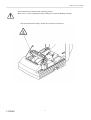
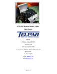
This Caution label is attached in the following position.
Make sure to use this equipment properly reading the cautions for handling carefully.
This label indicates the danger of burn due to the heat of print head.
CITIZEN
9
iDP-3210 User’s Manual
Ordinary Maintenance
l
l
l
l
l
Make sure to maintain the equipment after switching OFF the power .
When cleaning the platen of printer mechanism, wipe out the dirty portion by a cotton pud dipped into
ethyl alcohol.
When cleaning the surface of the main unit case, use soft cloth. In case the dirty portion can not be cleared out by
the soft cloth, use wet cloth squeezed tightly.
Absolutely do not use thinners, trichlene, benzine or ketone group solvents, or chemical-impregnated cleaning
cloths.
In case the print head becomes dirty because of paper dust, clean it by using a soft brush.
Cautions : Do not conduct the maintenance right after printing,
since print head and motor are so hot.
l
Head Cleaning
(1) Referring to "4. Operation 4.6 Removing of Paper Jam", remove the platen roller unit.
(2) Apply ethyl alcohol on a cotton pud and use this to wipe off dust on the surface of a heating unit.
(3) Mount the platen roller unit.
Cautions : Do not touch the surface of a heating unit of the print head by naked hands or metal objects.
Do not carry out these procedures right after printing due to the heat of head motor.
CITIZEN
10
iDP-3210 User’s Manual
CONTENTS
1. OUTLINE ....................................................................................................................................................................... 13
1.1 Features ..................................................................................................................................................................... 13
1.2 Unpacking ................................................................................................................................................................. 13
2. BASIC SPECIFICATIONS............................................................................................................................................ 15
2.1 Model Classification ................................................................................................................................................. 15
2.2 Basic Specifications .................................................................................................................................................. 16
2.3 Printing Paper Specifications .................................................................................................................................... 17
2.3.1 Recommended Paper ............................................................................................................................................ 17
2.3.2 Printing position ................................................................................................................................................... 18
2.3.3 Head and Cutter Layout........................................................................................................................................ 18
3 OUTER APPEARANCE AND COMPONENTS ........................................................................................................... 19
4.OPERATION................................................................................................................................................................... 20
4.1 Connecting AC Adapter............................................................................................................................................ 20
4.2 Connecting Interface Cable....................................................................................................................................... 21
4.3 Connecting Drawer Kickout Connector.................................................................................................................... 22
4.4 Inserting the Paper Roll............................................................................................................................................. 23
4.5 How to Remove Remaining Roll Paper .................................................................................................................... 25
4.6 Removing Paper Jam ................................................................................................................................................ 25
4.7 Canceling Cutter Lock .............................................................................................................................................. 27
4.8 Cleaning Print Head .................................................................................................................................................. 28
5 Dip Switch Setting ........................................................................................................................................................... 31
5.1 Location of Dip Switch ............................................................................................................................................. 31
5.2 Dip Switch Setting .................................................................................................................................................... 32
6. INTERFACE (Connecting with Peripheral Equipment)................................................................................................. 33
6.1 Parallel Interface ....................................................................................................................................................... 33
6.1.1 Specifications ....................................................................................................................................................... 33
6.1.2 CONNECTOR’S PIN CONFIGURATION......................................................................................................... 33
6.1.3 I/O SIGNALS....................................................................................................................................................... 34
6.1.4 Electrical Characteristics ...................................................................................................................................... 35
6.1.5 TIMING CHART ................................................................................................................................................. 36
6.1.6 Data Receiving Control ........................................................................................................................................ 36
6.1.7 Buffering .............................................................................................................................................................. 36
6.2 Serial Interface .......................................................................................................................................................... 37
6.2.1 Specifications ....................................................................................................................................................... 37
6.2.2 Connector’s Pin Configurations ........................................................................................................................... 38
6.2.3 I/O SIGNALS....................................................................................................................................................... 39
6.2.4 Data Configuration ............................................................................................................................................... 40
6.2.5 Error Detection ..................................................................................................................................................... 41
6.2.6 Data Receiving Control ........................................................................................................................................ 41
6.2.7 Buffering .............................................................................................................................................................. 41
CITIZEN
11
iDP-3210 User’s Manual
7. Drawer Kickout Connector............................................................................................................................................. 43
7.1 Specifications............................................................................................................................................................ 43
7.2 Connector’s Pin Configurations................................................................................................................................ 43
7.3 Drive Circuit ............................................................................................................................................................. 43
8 POWER SUPPLY CONNECTOR SPECIFICATIONS.................................................................................................. 44
9 PRINT CONTROL FUNCTION..................................................................................................................................... 45
9.1 Command List........................................................................................................................................................... 45
9.2 Command Details...................................................................................................................................................... 46
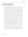
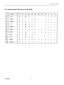
10 CHARACTER CODE TABLE ..................................................................................................................................... 61
10.1 International (IBM Character #2)............................................................................................................................ 61
10.2 International Character Code Table ........................................................................................................................ 62
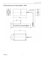
Appendix 1 Outline Drawing.............................................................................................................................................. 63
1.1Outler Drawing of Printer (Model : iDP-3210).......................................................................................................... 63
1.2Outer Drawing of AC Adapter (Model : 30AD) ........................................................................................................ 64
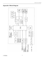
Appendix 2 Block Diagram ................................................................................................................................................ 65
CITIZEN
12
iDP-3210 User’s Manual
1. OUTLINE
This printer, a small-sized line thermal printer, has been developed to be applicable to various data
communication terminals, POS terminals, kitchen printers, etc..
Since the printer is equipped with abundant functions, it can be used widely in various applications.
Read this manual thoroughly before you start using the printer.
1.1 Features
(1) Light weight and small foot print.
(2) Easy paper setting due to auto loading function.
(3) Easy maintenance and cleaning of print head due to the removable platen design.
(4) High speed printing and quiet printing due to Line thermal printing .
(5) High reliability due to long life of printer head and simple design.
(6) Input buffer incorporated.
(7) Bar code printing is available. (Exclusive command)
(8) Drawer kick-out interface incorporated.
(9) Equipped with an auto cutter.
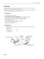
1.2 Unpacking
(1) Upon unpacking the printer, make sure that the following parts are contained in this package.
Printer main unit
x1
Sample paper roll
x1
AC Adapter
x1
AC power supply cord
x1
User’s Manual
x1
CITIZEN
13
iDP-3210 User’s Manual
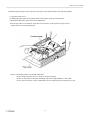
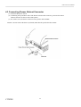
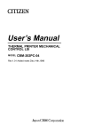
(2) When using the printer, remove the protective paper of the thermal head in the following manner:
1) Open the printer cover.
2) Holding the paper guide of the platen roller section, pull it in the arrowed direction.
3) Pull out the protective paper in the arrowed direction.
4) In case the printer is not used for a long time period of time, set the protective paper to keep
platen roller away from thermal head.
Caution : Install this printer on a flat and stable table.
Do not install this printer near to a heater or in direct sunlight.
Do not use this printer in locations with high temperature, high humidity or heavy dirt.
In case of the occurrence of dew condensation, do not switch the power ON until it goes out
.
CITIZEN
14
iDP-3210 User’s Manual
2. BASIC SPECIFICATIONS
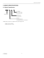
2.1 Model Classification
iDP3210 - R
F
120
AC Adapter
120 : for AC 120V
230 : for AC 230V
Model name
Character set
F: International
Interface
R: Serial (RS232C)
P: Parallel(Conforms to Centronics)
*Model name of exclusive AC Adapter and AC power supply cord
30AD-U (120V 3 pin cord)
30AD-E (230V class 1 cord)
CITIZEN
15
iDP-3210 User’s Manual
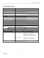
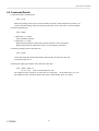
2.2 Basic Specifications
Item
Printing system
Print width
Dot pitch
Printing speed
No. of printing columns
Character size
Character type
Bar code type
Line pitch
Paper
Interface
Input buffer
Power supply voltage
Power consumption
Spec. of AC Adapter
Model
Weight
External dimensions (main body)
Operating temperature/humidity
Storage temperature/humidity
Reliability
Description
Line thermal dot printing system
73.92 mm/448 dots
Horizontal 0.165mm (approx. 6 dots/mm)
Vertical
0.163mm (1/156 inch)
73.3mm/sec. (Max. Print density = Standard) (450 dot line/sec)
44 columns (10 x 16 dots)or 42 columns (10 x 16 dots)
(can be selected by dip switch.)
1.485mm x 2.61mm (9 x 16 dots)
Alphanumeric, International characters
UPC-A/E, JAN(EAN) 13 columns/18 columns, ITF
CODE 39, CODE 128, CODABAR
1/6 inch (approx. 4.23mm) (can be selected by Command)
Min. 1/156 inch (approx. 0.163mm)
Thermal roll paper 80 mm x Ø83 mm (MAX)(See Paper Spec..)
Serial (RS-232C), Parallel (Conforms to Centronics.)
4K byte
DC 24 ± 7%
100W
Rated input : AC100V - 240V, 50/60HZ, 120VA
Rated output : DC24V, 1.8A
30AD-U(For 120)
30AD-E(For 230V)
Main unit : 1.3 kg, AC Adapter : 0.45 kg
152(W) x 201(D) x 123(H)
5 - 40°C, 35 - 85%RH (free of dew condensation)
- 20 - 60°C, 10 - 90%RH (free of dew condensation)
Print head’s life :
Pulse resistance 50 million pulses
Wear resistance 100 Km
(Printing ratio 12.5%, normal temperature,
normal humidity, recommended paper)
Auto cutter’s life :
500,000 cut (Normal temperature,
normal humidity, recommended paper)
Safety / EMI Standard
CITIZEN
120V Model : UL-C-UK, FCC Class A
230V Model : TUV, GS, CE, Marking
16
iDP-3210 User’s Manual
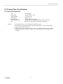
2.3 Printing Paper Specifications
2.3.1 Recommended Paper
Type
Paper width
Paper thickness
Roll diameter
Printed surface
Recommended paper
Core
Caution :
CITIZEN
: Thermal paper
: 80 plus 0/minus 1 mm
: 65 ± 5 micro m
: Ø83mm or less
: Outside of the roll (surface)
: TF50KS-E2C by Nippon paper Mil. or other equivalent
: Ø12mm (inner diameter), Ø18mm (outer diameter)
1. Print quality may vary if you use paper other than specified.
2. In such case, change print density by dip switch setting. (See “5 Dip Switch Setting”)
3. Do not paste the paper to the core.
4. Chemicals or oil may change the color of paper, or printed characters may be vanished.
5. Change of paper color starts from approx. 70°C. Pay attention to heat, humidity and
sun light.
17
iDP-3210 User’s Manual
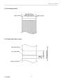
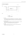
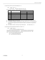
2.3.2 Printing position
2.3.3 Head and Cutter Layout
CITIZEN
18
iDP-3210 User’s Manual
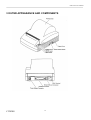
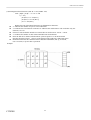
3 OUTER APPEARANCE AND COMPONENTS
CITIZEN
19
iDP-3210 User’s Manual
4.OPERATION
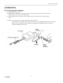
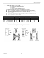
4.1 Connecting AC Adapter
(1) Turn off the power switch.
(2) Holding the AC Adapter cable connector with its arrowed side facing downward, put it into the
power connector on the rear side of the printer.
(3) Connecting the AC power cord to the AC Adapter, put the AC plug of the cord into the plug
socket.
! Cautions : Do not use the power supply unit other than the specified.
In connecting / removing the cable connector, make sure to do this holding the side of arrow mark.
Make sure to use the power outlet for this power supply unit separated from the one used for
the other equipment creates noise.
CITIZEN
20
iDP-3210 User’s Manual
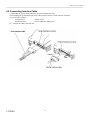
4.2 Connecting Interface Cable
(1) Turn OFF the power switch. (Both for the printer and the host side.)
(2) Confirming the up and down side of the cable terminal, connect it to the interface connector.
(3) Fix the cable terminal.
Serial interface:
Tighten screws.
Parallel interface:
Turn to tighten the fixing parts.
(4) Connect the cable to the host side.
CITIZEN
21
iDP-3210 User’s Manual
4.3 Connecting Drawer Kickout Connector
(1) Turn OFF the power switch.
(2) Confirming the up and down side of the drawer kickout cable connector, put it into the drawer
kickout connector on the rear side of the printer.
(3) Fix, with a screw, the drawer earth wire to the printer earth terminal.
Cautions : Do not connect the drawer (solenoid) other than the specified in this manual.
CITIZEN
22
iDP-3210 User’s Manual
4.4 Inserting the Paper Roll
Cautions : Do not use a paper roll other than the one specified in this manual.
In case of using a paper roll other than the one specified, there is a case the
print quality and reliability may not be guaranteed.
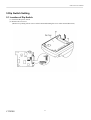
(1)
Holding the projections on both sides of the printer cover, open it until it stops.
Cautions : The printer cover is not detachable. Do not try to further open beyond the stop position.
Do not insert the paper roll with its end fluffed or bent.
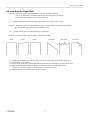
(2)
Cut the end of paper roll approximately at a right angle.
Cautions : Do not insert the paper roll with its end fluffed or bent.
Good
Good
Good
No Good
(3)
(4)
(5)
(6)
No Good
No Good
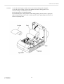
Confirming winding direction of the paper roll, put it on the roller section of the upper cover.
Turn ON the power switch.
Insert the tip of the paper roll straight into the paper inlet (as indicated by an arrow on the case).
Paper is automatically pulled into the platen roller and comes out of the paper outlet.
As excessive portion of paper is automatically cut off, remove it away.
(7) With the printer cover closed, printer is ready to print.
CITIZEN
23
iDP-3210 User’s Manual
Cautions :
CITIZEN
In case the slack of paper remains, remove the slack by rolling up the roll paper.
In case the paper is tilting, keep pressing FEED switch after closing printer cover.
Then, this tilting is automatically corrected.
Do not open printer cover during printing.
Do not hold the paper coming from the outlet during printing, this may cause a paper jam.
When using auto paper cutter at full cut mode, please remove printed paper which was cut
before next printing starts.
24
iDP-3210 User’s Manual
4.5 How to Remove Remaining Roll Paper
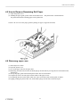
(1) Open the printer cover.
(2) Holding the paper guide, pull it in the arrowed direction. The platen roller is detached from
the print head and the remaining paper can be pulled out.
Caution : Be sure to use the paper guide for pulling out paper. (Opposite direction)
4.6 Removing Paper Jam
(1) Turn Off power switch
(2) Open the printer cover.
(3) Cut off the paper roll near the paper inlet.
(4) Detaching, from the chassis hook, the head springs on both sides by moving them in arrowed direction,
lift them up.
(5) Lift up the paper guide knob and the platen roller unit can be detached.
(6) Completely remove the roll paper remains inside of the paper course.
(7) Confirming direction of the platen roller unit, insert it into the inside of bush guide of chassis.
(8) Lightly pushing the platen roller unit, fit the head springs on both sides on the hook part.
CITIZEN
25
iDP-3210 User’s Manual
Caution : Since print head and motor are hot, do not carry out this action right after printing.
In case of moving the head springs, do not move it beyond the removable range of
the springs.
When removing the remaining paper, do not touch the surface of heating unit
of the print head by naked hands or by a metal piece etc.
Except for the necessary case of removing paper jam, do not remove
the platen roller unit.
In case of inserting paper roll, make sure to confirm this was inserted correctly.
CITIZEN
26
iDP-3210 User’s Manual
4.7 Canceling Cutter Lock
(1) As referring to "4.6 Removing Paper Jam", remove the roll paper remains inside the paper course.
(2) Press the FEED switch. The auto cutter performs initialization, returning the blade to home position and
canceling alarm state.
(3) If the blade does not return to home position or alarm state is not canceled by Item 2 operation, turn off
the power switch and, by turning the emergency knob inside the hole at the bottom of the main unit in
the arrowed direction, return the auto cutter blade to home position.
(4) Fully remove remaining paper on the cutter blade through using tweezers.
Caution : Since print head and motor are hot, do not carry out this action right after printing.
For removing the remaining paper, do not touch the surface of heating unit
of the print head by naked hands or by a metal piece etc.
Paper cutter enable/disable can be selected by dip switch setting.
In case of using this printer at paper cutter disable mode, make sure to confirm
the cutter blade is in the home position.
In case the cutter blade is not in the home position, return this blade to the home position
by following the above procedure.
CITIZEN
27
iDP-3210 User’s Manual
4.8 Cleaning Print Head
(1) As referring to "4.6 Removing Paper Jam”, remove the platen roller
unit.
(2) Using a cotton pud containing ethyl alcohol, wipe off dust, etc. on the surface of the surface of the head.
heating unit.
(3) Mount the platen roller unit.
Caution : Do not touch the surface of heating unit of the print head by naked hands or by a metal piece etc.
Since print head and motor are hot, do not carry out this action right after printing.
CITIZEN
28
iDP-3210 User’s Manual
4.9 OPERATION PANEL AND DISPLAY OF ERROR
(1) POWER LAMP (Green)
With power switch is turned ON, this lamp lights up. Further, when "Memory Check Error" has occurred,
this lamp lights up, too.
(2) ERROR LAMP (Red)
Error details are indicated by lighting or blinking state as follows.
DISPLAY PATTERN
ERROR DETAIL
POWER LED
RESETTING METHOD
ERROR LED
Memory check error
Illuminated
Not possible
(Quick blinking)
Cover open
Illuminated
Illuminated
Close the cover
Print Head overheat
Illuminated
Illuminated
Automatically recovered when
cooled.
Paper near end
Illuminated
Illuminated
Set new paper
Paper end
Illuminated
Set new paper
(Quick blinking)
Cutter motor lock
Illuminated
Eliminate paper jam
(Quick blinking
& slow blinking)
Macro execution wait
Illuminated
Press FEED switch.
(slow blinking)
CITIZEN
29
iDP-3210 User’s Manual
Details of error
Cover open
:
Print Head overheat :
Paper near end
:
Paper end
:
Cutter motor lock :
When printer cover is opened, printer cover open sensor detects the cover
opening and has ERROR LED illuminate, then stops printing operation.
But, depending on dip switch setting, paper feed can be performed when printer cover
is opened.
To protect print head from excessive heat, in case the temperature of print head
goes high(approx. 65°C or over), head temperature sensor works and has ERROR
LED illuminate, then stops printing operation.
After head temperature is cooled (Approx. 60°C or less), printing operation
automatically starts.
When the remaining of roll paper goes scarce, paper near end sensor located on the side
of roller portion of the upper cover works,
and has ERROR LED illuminate to show the remaining of roll paper is getting scarce.
(See “setting of paper end detector effective for outputting a signal for no paper”
and “setting of paper end sensor effective for print stop” in the chapter of print control
function.)
When the roll paper runs out completely, the paper sensor located in the paper course
near to print head detects the end of print paper and has ERROR LED illuminate, then
stops printing operation.
(See “setting of paper end sensor effective for outputting a signal for no paper” and
“setting of paper end sensor effective for print stop” in the chapter of print control
function.)
When the paper is inserted into the paper course near to print head, roll paper is
automatically loaded.
In case that cutter position sensor locates in the auto cutter unit keeps ON or OFF for
one second or more during the operation of cutter motor, this sensor detects it
as motor lock state.
And then, this stops cutter operation and printing operation.
(See the chapter of 4.5 “cancellation of cuter lock”)
(3) FEED Switch
With this pressed once shortly, paper is fed by one line. With this kept pressed, lines
are fed continuously. In case of macro execution wait, this is executed by pressing FEED switch.
(4) FEED Switch and Power Switch
By turning ON power switch with pressing FEED SWITCH, , self printing is performed.
CITIZEN
30
iDP-3210 User’s Manual
5 Dip Switch Setting
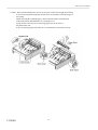
5.1 Location of Dip Switch
(1) Turn OFF the power switch.
(2) Remove the rear cover.
(Remove it by taking off two screws at the bottom and turning the cover in the arrowed direction.)
CITIZEN
31
iDP-3210 User’s Manual
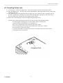
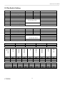
5.2 Dip Switch Setting
DS1
-1
-2
-3
-4
-5
-6
-7
-8
-9
FUNCTION
Paper cutter
Cover open
CR switching
Unused
Print columns
International Characters
International Characters
International Characters
Print density
-10
Print density
ON
Enabled
Disabled
LF activate
OFF
Disabled
Enabled
Ignored
44 columns
FACTORY SETTING
ON
OFF
OFF
OFF
ON
OFF
OFF
OFF
OFF
42 columns
See the table below.
See the table below
ON
DS2
FUNCTION
ON
OFF
-1
Bit length
7 bits
8 bits
-2
Parity
Provided
Not provided
-3
Odd/even
Even
Odd
-4
DTR/XON-XOFF
XON-XOFF
DTR/DSR
-5
BAUD RATE
-6
BAUD RATE
-7
BAUD RATE
See the table below.
-8
Unused
-----------------(Note) DS2 is available only for serial interface.
PRINT DENSITY
DS1-9
DS1-10
1200
ON
ON
OFF
32
ON
ON
OFF
ON
2400
OFF
OFF
ON
4800
ON
OFF
ON
JAPAN
600
OFF
ON
OFF
OFF
OFF
OFF
ON
DARKER
ON
ON
ITALY
300
ON
OFF
OFF
ON
ON
ON
OFF
SWEDEN
OFF
OFF
ON
OFF
DARK
OFF
ON
DENMARK 1
ON
ON
OFF
OFF
U.K.
150
OFF
OFF
OFF
GERMANY
CITIZEN
OFF
OFF
OFF
OFF
STANDARD
ON
OFF
FRANCE
BAUD RATE
DS2-5
-6
-7
U.S.A.
INTERNATI
ONAL
DS1-6
DS1-6
-7
-8
LIGHT
OFF
OFF
FACTORY SETTING
OFF
OFF
OFF
OFF
OFF
ON
ON
OFF
OFF
OFF
ON
ON
ON
ON
ON
ON
9600
OFF
ON
ON
19200
ON
ON
ON
iDP-3210 User’s Manual
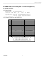
6. INTERFACE (Connecting with Peripheral Equipment)
6.1 Parallel Interface
6.1.1 Specifications
Data input method : 8 bit parallel signal (DATA 1 - 8)
Control signals: ACK ,BUSY ,STB
,FAULT
Applicable connector :
,PE
,RESET
Printer side 57LE-40360 (Equivalent to amphenol )
Cable side 57-30360 (Equivalent to amphenol )
6.1.2 CONNECTOR’S PIN CONFIGURATION
No.
1
2
3
4
5
6
7
8
9
10
11
12
13
14
15
16
17
18
CITIZEN
SIGNAL NAME
STB
DATA 1
DATA 2
DATA 3
DATA 4
DATA 5
DATA 6
DATA 7
DATA 8
ACK
BUSY
PE
+5V DC
GND
FRAME GND
No.
19
20
21
22
23
24
25
26
27
28
29
30
31
32
33
34
35
36
33
SIGNAL NAME
TWISTED PAIR GND
TWISTED PAIR GND
TWISTED PAIR GND
TWISTED PAIR GND
TWISTED PAIR GND
TWISTED PAIR GND
TWISTED PAIR GND
TWISTED PAIR GND
TWISTED PAIR GND
TWISTED PAIR GND
TWISTED PAIR GND
TWISTED PAIR GND
RESET
FAULT
GND
Drawer switch output
+5V DC
iDP-3210 User’s Manual
6.1.3 I/O SIGNALS
(1) Input Signals to the Printer
l DATA
: 8-bit parallel signal (positive logic)
l STB
: Strobe signal to read 8-bit data (negative logic)
l RESET
: Signal to reset the entire printer (negative logic) 1m sec or more
(2) Output Signals from Printer
l ACK
: An 8 bit data request signal. Pulse signal output at the end of
the BUSY signal. (negative logic)
l BUSY
: The signal to indicate BUSY state of the printer. Input new data for "LOW".
(positive logic)
l FAULT
: The signal which is made "LOW" when the printer is in alarm state. All the
l
l
control circuits inside the printer are stopped at this time.(negative logic)
PE
: The signal which is output when paper runs out or goes scarce. (positive logic)
Drawer Switch Output
: With the switch open, this signal goes "HIGH". When shorting, this goes
"LOW".
(3) Power supply
l +5 V DC
l GND
CITIZEN
: This is 5V pulled up by a 3.3k Ohm resistor.
: This is the common ground for the circuit.
34
iDP-3210 User’s Manual
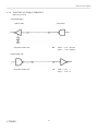
6.1.4 Electrical Characteristics
(1) Input Signal Level
All the input signals are at C-MOS level.
"HIGH" level
: 4.0V MIN
"LOW" level
: 1.0V MAX
(2) Output Signal Level
All the output signals are at C-MOS level.
"HIGH" level
: 4.5V MIN
"LOW" level
: 0.1V MAX
(3) I/O Conditions
Both input signal of STB and RESET are pulled up by 3.3K Ohm, and all of the other is pulled up
by 50K Ohm.
<Printer side>
<Host side>
All the output signals are pulled up by 50K Ohm.
CITIZEN
35
iDP-3210 User’s Manual
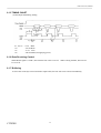
6.1.5 TIMING CHART
(1) Data Input and Printing Timing
T1, T2, T3 : 0.5λs MIN
T4
: 270 ns MAX
T5
: 2.3λs TYP
T6
: 500 ms MIN (On supplying power)
6.1.6 Data Receiving Control
When BUSY signal is "LOW", data from the host can be received. When it being "HIGH", data can not
be received.
6.1.7 Buffering
As the buffer of 4K byte can be buffered in input buffer, the host side can be released immediately.
CITIZEN
36
iDP-3210 User’s Manual
6.2 Serial Interface
6.2.1 Specifications
(1) Data transfer system: Asynchronous
(2) Baud rates
150, 300, 600, 1200, 2400, 4800, 9600, 19200 bps (Selectable by user)
(3) Configuration of one word
Start bit : 1 bit
Data bit : 7 bits or 8 bits (Selectable by user))
Parity bit : Add/even or no parity (Selectable by user)
Stop bit : 1 bit or more
(4) Signal polarity
RS-232C
l Mark
= Logic " 1" (-3V - -12V)
l Space
= Logic " 0" (+3V - +12V)
(5) Receive data (RD signal)
RS-232C
l
Mark
= 1
l Space
= 0
(6) Data receiving control (DTR signal)
RS-232C
l
Mark
: Data transfer not available
l Space
: Data transfer available
(7) Data transmission control (TD signal)
DC1 code (11H) X-ON
: Data reception available
DC3 code (13H) X-OFF : Data reception not available
CITIZEN
37
iDP-3210 User’s Manual
6.2.2 Connector’s Pin Configurations
No.
1
7
3
20
2
6
SIGNAL NAME
FG
GND
RD
DTR
TD
DSR
I/O
Input
Output
Output
Input
FUNCTION
Frame Grand
Signal GND
Receiving data
Printer BUSY signal
Transmission data
Data set READY
Applicable connector (D-Sub connectors)
Printer side : 17LE-13250 (Equivalent to DDK)
Cable side
: 17JE-23250 (Equivalent to DDK )
Cautions : 1. Signal for RS-232C conforms to EIA RS-232C.
2. In case the receiving data is not being transmitted, keep receiving data in mark state.
CITIZEN
38
iDP-3210 User’s Manual
6.2.3 I/O SIGNALS
(1) RD
Serial receiving data signal. On occurrence of framing error, overrun error, or parity error,
the data is printed as "?".
(2) DTR
When this signal is READY, write data or a command. When they are written in
BUSY, overrun error is occurred and data is ignored. Even during printing, data can be
loaded in the input buffer. Further, BUSY can take place on supply of power, during test
printing, during on-line, or on resetting.
(3) TD
When, while in data reception, the input buffer on the printer side has only 128 bytes .or less left,DC3
(13H) data reception impossible signals are output. When the input buffer has 256 bytes
left, DC1 (11H) data reception possible signals are output to the host. When DTR/DSR
control having been selected in status information transmission, it is first confirmed that
DSR is "space" and data is sent. When DTR/DSR control has not been selected, DSR
is ignored and data is transmitted.
(4) FG
Case GND
(5) GND
Common GND on the circuit.
CITIZEN
39
iDP-3210 User’s Manual
6.2.4 Data Configuration
-------à t
Mark
Space
1
2
1.
2.
3.
3
Start bit
Data bit (+ parity bit)
Stop bit ( 1 or more )
(1) Start Bit
In 1/2 bit from the mark-to-space starting edge, state is read once again. When "space"
state is confirmed, it is recognized as the start bit. If it is "mark" state, it is not taken as
the start bit. Without taking it as an error, detection of a start bit is carried out once again.
(2) Data Bit + Parity Bit
Data bit and parity bit are sampled at 1/2 start bit for time length equal to 1 bit. The state
thus sampled is taken as the data for the bit concerned. Bits are named as
Bit 0, Bit 1, ..... parity bit counted from the one close to the start bit.
(3) Stop Bit
The stop bit is a mark level of 1 bit or more. With "space" having been detected on
detection of a stop bit, framing error takes place.
CITIZEN
40
iDP-3210 User’s Manual
6.2.5 Error Detection
Parity, framing, and overrun are detected. On detection of any error, the data are stored
in the buffer as "?".
(1) Framing Error
With "space" state having been detected on detection of a stop bit, error takes place.
The data are stored in the buffer as "?".
(2) Parity Error
With an error having been detected under specifying parity check, the data is stored in the buffer as "?".
(3) Overrun Error
On detection of an overrun error, the data are stored in the buffer as "?".
6.2.6 Data Receiving Control
When DTR/DSR control having been selected, with BUSY signal at "LOW", data from the host side are
received. With the signal at "HIGH", they can not be received.
When DTR/DSR control not having been selected, after X-ON transmission, data is received from the host
side. No transmission of data can take place after X-OFF is transmitted.
6.2.7 Buffering
Data transfer to the input buffer include DTR signals and TD signals as the control signals concerned.
(1) DTR signals (See 4.2.3 (2).)
(2) TD signals (See 4.2.3 (3).)
CITIZEN
41
iDP-3210 User’s Manual
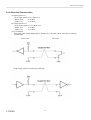
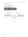
6.2.8 ELECTRICAL CHARACTERISTICS
(1) RS-232C Circuit
Input (RD, DSR)
(Printer Side)
(Host Side)
Equivalent to Max 232
RD
Mark = <-8V> : Stop bit
Space = <+8V>: Start bit
TD
Mark = <-8V> : 1
Space = <+8V>: 0
Output (DTR, TD)
Equivalent to Max 232
CITIZEN
42
iDP-3210 User’s Manual
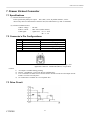
7. Drawer Kickout Connector
7.1 Specifications
(1) Drawer-Kick Drive Signal
Pulses specified by ESCp are output. Also, SW(+) state, in parallel interface, can be
observed by Pin 34 of the interface connector and, in serial interface, by ESC u command.
(2) Electrical Characteristics
1) Drive voltage :
2) Drive current :
3) SW signal
:
DC24V
Max. 0.8A (within 510ms)
signal level "L"= 0 - 0.5V
"H"= 3 - 5V
7.2 Connector’s Pin Configurations
No.
1
2
3
4
5
6
SIGNAL NAME
FG
DRAWER 1
DRSW
VDR
DRAWER 2
GND
FUNCTION
Frame ground
Drawer 1 driving signal
Drawer SW input
Drawer driving power supply
Drawer 2 driving signal
Common ground on the circuits
Connector used
: TM5RJ3-66 (Hirose) or equivalent
Applicable connector : TM3P-66P (Hirose) or equivalent
Caution
1)
2)
3)
4)
No output is available during printing.
Drawer 1 and Drawer 2 can not be driven simultaneously.
Use a solenoid of 36 Ohm or more for the drawer. Do not exceed 0.8A for output current.
Failure or seizure can take place.
No connection is available to a to a telephone line.
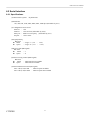
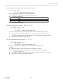
7.3 Drive Circuit
CITIZEN
43
iDP-3210 User’s Manual
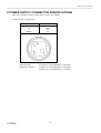
8 POWER SUPPLY CONNECTOR SPECIFICATIONS
This is the connector for power supply from exclusive AC Adapter.
Connector’s Pin Configurations
No.
1
2
3
SHELL
Connector used
Applicable connectors
CITIZEN
Function
+24V
GND
N.C
F.g
: TCS7960-53-2010 (Hoshiden) or equivalent
: TCP8927-63-1100 (Hoshiden) or equivalent
TCP8927-53-1100 (Hoshiden) or equivalent
44
iDP-3210 User’s Manual
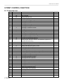
9 PRINT CONTROL FUNCTION
9.1 Command List
FUNCTION
CONTROL CODE
1
2
3
4
5
6
7
8
9
10
11
12
13
14
15
16
17
18
HT
CR
LF
ESC SP
!
%
&
*
2
3
@
D
E
G
J
R
c3
Horizontal tab command
Print command
Printing and paper feed
Setting the right space amount of the character
Collective specifying printing mode
Specifying/canceling download character set
Defining download characters
Specifying the bit image mode
Specifying/canceling underline
Specifying 1/6-inch line feed rate
Setting line feed rate n/203 inch
Initializing the Printer
Setting horizontal tab position
Specifying/canceling highlighting
Specifying/canceling double printing
Printing and feeds paper n/203 inch
Selecting the international characters
Setting of paper end sensor effective for outputting a signal for no
paper(Parallel Mode Only)
19
20
21
22
23
24
25
26
27
28
29
30
31
32
33
34
35
36
37
38
39
40
41
c4
c5
d
p
t
v
u
{
V
$
¥
GS k
w
h
H
*
/
:
^
ESC =
a
i
m
Setting of paper end sensor effective for print stop
Enabling/disabling the panel switches
Printing and feeding the paper by n lines
Generating the specified pulse(Drawer Kickout)
Selecting the character code table
Transmitting the printer status(Serial Mode Only)
Transmitting the status of peripheral equipment(Serial Mode Only)
Specifying/canceling the inverted characters
Specifying/canceling the 90° - right-turned characters
Specifying the absolute positions
Specifying the relative positions
Printing the bar code
Selecting the horizontal size (scale factor) of bar code
Selecting the height of the bar code
Selecting the font of HRI character
Defining the download bit image
Printing the download bit image
Starting/ending macro definition
Executing the macro
Data input control
Aligning the characters
Full cut
Partial cut
CITIZEN
45
PAGE
iDP-3210 User’s Manual
9.2 Command Details
(1) Horizontal Tab Command (HT)
Code : (09)h
Shifts the printing position to the next horizontal tab position. The horizontal tab position is set
by ESC D. Initial setting of the horizontal tab position is in 9th, 17th, 25th, 33rd, 41st columns.
(2) Print Command (CR)
Code : [0D]h
1) When DS 1 -3 is OFF:
This command is ignored.
2) When DS 1- 3 is ON:
With data held inside the input buffer, printing and line feed are performed.
Without data inside the input buffer, however, no printing is performed.
(3) Printing and Paper Feed Command (LF)
Code : [0A]h
Prints data inside the internal input buffer and feeds lines based on the line feed
amount having been set.
(4) Setting the right space amount of the characters (ESC SP)
Code : [1Bh] + [20h] + n
* {0 ≤ n ≤ 20} Data is described in Hex code.
The rightward space amount is set in dot unit (0.165 mm unit). In the initial value, it is n=0.
The rightward space amount in double wide mode is made double of the set volume.
CITIZEN
46
iDP-3210 User’s Manual
(5) Specifying Collectively the Print Mode (ESC ! n)
Code: [1Bh] + [21h] + n ≤
* {0 ≤ n ≤ FF} The data is described in Hex code.
Printing mode is assigned. Each n bit indicates the following:
BIT
FUNCTION
VALUE
0
1
1
Undefined
2
Undefined
3
Undefined
4
Highlighting
Canceled
Specified
5
Double height
Canceled
Specified
6
Double width
Canceled
Specified
7
Undefined
8
Underline
Canceled
Specified
l With double height and double width being specified simultaneously, double wide and
double high characters are consisted.
l An underline is attached to the full character width, which, however, is not attached to the
part having been skipped by the horizontal tab. Neither is it attached to 90°-right-turned
characters.
l The underline width is as having been specified by ESC -. The initial value is "1".
(6) Specifying/Canceling Download Character Set (ESC % n)
Code: [1B]h + [25]h + n
* {0 ≤ n ≤ FF} Data is described in Hex code.
Specifying/canceling download characters. Download characters and download bit
images cannot be defined simultaneously. Further, only the lowest bit (n0) is valid
for n. The lowest bit (n0) indicates the following:
n0= 0: Canceling download character
n0= 1: Specifying download character
CITIZEN
47
iDP-3210 User’s Manual
(7) Defining Download Character (ESC & s n m a (D1D2 - Dn)
Code: [1B]h + [26]h + s +n +m +a +Dn
* {s = 02}
{20 (Hex) ≤ n ≤ 7E (Hex)}
{20 (Hex) ≤ m ≤ 7E (Hex)}
{0 ≤ a ≤ 0A (Hex)}
Defines the font of download characters of alphanumeric characters.
"s" indicates the number of bytes in vertical direction.
"n" indicates the start character code and “m” indicates the end character code. To define only one
character, set n=m.
l Character codes definable includes 95 ASCII codes in total between <20>H - <7E>H.
l "a" indicates the number of dots in horizontal direction for definition.
l Dn is the data to be defined, which indicate a pattern equal to "a" dot in horizontal
direction from the left end. The rest of the pattern on the right side is filled with space.
l Download characters thus defined remain valid until redefinition, ESC @ execution,
GS * execution, or power OFF is practiced.
Example
l
l
CITIZEN
48
iDP-3210 User’s Manual
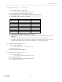
(8) Specifying the Bit Image Mode (ESC * m n1 n2 D1 - Dn)
Code : [1B]h + [2A]h + m + n1 + n2 + Dn
* {m= bit image mode (See the table below.)}
{0 ≤ n1 ≤ FF}
{0 ≤ n2 ≤ 02} Data is described in Hex code.
According to the bit image mode assigned in m, prints data in the bit image.
l The no. of dots printed is divided by 256, whose quotient is taken as n2 and residualas n1.
l The total no. of dots printed in the bit image is equal to n1 + (256 x n2).
l When bit image data have been input in excess of 1 dot/line (448 dots) position, the excess
data are discarded.
l In the bit image data (Dn), the bits subject to printing are taken as "1" and those not as "0".
l The bit image modes are shown as follows:
VERTICAL DIRECTION
HORIZONTAL DIRECTION
m(Hex)
MODE
NO. OF DOTS DOT DENSITY DOT DENSITY MAX. NO OF DOTS
0
8-dot single density
8
78 DPI
77 DPI
224
1
8-dot double density
8
78 DPI
154 DPI
448
32
16-dot single density
16
156 DPI
77 DPI
224
33
16-dot double density
16
156 DPI
154 DPI
448
l When the value set in m (bit image mode) are out of conditions, the data following after n1 is
processed as printing data.
The relation between bit image data and printing dots are shown below.
CITIZEN
49
iDP-3210 User’s Manual
(9) Specifying/ Canceling Underline (ESC - n)
Code: [1B]h + [2D]h + n
* {0 ≤ n ≤ 02} Data is described in Hex code.
Specifying/canceling an underline.
l An underline is attached to the full character width. It is, however, not attached to the part
having been horizontal tab command.
l An underline is not attached to a 90 °- right-turned characters.
l Types of underlines by n value are shown below:
n (Hex)
0
1
2
Type
Canceling an underline.
Specifying an underline for 1-dot width.
Specifying an underline for 2-dot width.
(10) Specifying 1/6 inch line feed rate (ESC 2)
Code : [1B]h + [32]h
The line feed rate per line is specified by 1/6 inch.
(11) Setting line feed rate n/203 inch (ESC 3 n)
Code : [1B]h + [33]h + n
* {0 ≤ n ≤ FF} Data is described in Hex code.
The line feed rate per line is specified by n/156 inch.
l
The initial value is n = 26(18H), being 4.23 mm line feed rate.
(12) Initializing Printer (ESC @)
Code : [1B]h + [40]h
Clears data stored in the print buffer and brings various settings to the initial state (Default state).
l Data inside the internal input buffer are not cleared.
l Dip switches are read once again.
(13) Setting Horizontal Tab Position (ESC D n NUL)
Code : [1B]h + [44]h + n [00]h
* {0 ≤ n ≤ FF} Data is described in Hex code.
Specifying a horizontal tab position.
l "n" indicates the no. of columns from the beginning to the horizontal tab position. At this time,
n= set position - 1 is to be specified.
l The tab position is set at position where it is "character width x n" from the line beginning. The
character width, at this time, includes the rightward space amount. In double wide characters, it is
made double of the ordinary case.
l Tab positions can be specified are maximum 24. Specifying exceeding this is ignored.
l ESC D NUL clears all the set tab positions. Following clearing, horizontal tab command is ignored.
l Initial value is specified for each eight characters(9.17.25.33.41) of ANK characters.
CITIZEN
50
iDP-3210 User’s Manual
(14) Specifying/canceling highlighting (ESC E n)
Code : [1B]h + [45]h + n
* {0 ≤ n ≤ FF} Data is described in Hex code.
Specifying/canceling the highlighted characters.
l "n" is valid only for the lowest bit (n0).
l Control by the lowest bit (n0) is shown as follows:
l
l
n0
Type
0
Canceling highlighting.
1
Specifying highlighting.
This is effective to all characters.
Dot configuration of a highlighted character includes one extra dot added at its side.
(15) Specifying/canceling Double Printing (ESC G n)
Code : [1B]h + [47]h + n
* {0 ≤ n ≤ FF} Data is described in Hex code.
Specifying/canceling the double printing.
l "n" is valid only for the lowest bit (n0).
l Control by n is shown as follows.
l
n0
Type
0
Canceling double printing.
1
Specifying double printing.
The print result of Double printing and highlight character printing is completely same
.
(16) Printing and feeding paper n/203 inch (ESC J n)
Code : [1B]h + [4A]h + n
* {0 ≤ n ≤ FF} Data is described in Hex code.
Prints data inside the print buffer and feeds paper by n/156 inch.
l Specified volume does not remain.
l The beginning of the line is to be considered as the next printing start position.
CITIZEN
51
iDP-3210 User’s Manual
(17) Selecting International Characters (ESC R n)
Code : [1B]h + [52]h + n
* {0 ≤ n ≤ 0A) Data is described in Hex code.
Selecting international characters.
l Depending on the value of n, following character sets are specified.
n(Hex)
CHARACTER SET
0
U.S.A.
1
France
2
Germany
3
U.K.
4
Denmark 1
5
Sweden
6
Italy
7
Spain
8
Japan
9
Norway
A
Denmark 2
l The initial value of n indicates the character set specified by the dip switch.
However, setting is available only through use of this command for "Spain ", "Norway",
and "Denmark II".
(18) Setting of paper end detector available for output of paper end signal
Code : [1B]h + [63]h + [33]h + n
*{0 ≤ n ≤ FF} Data is described in Hex code
Specifying the condition of paper end detector to stop printing operation.
l n is valid only for the lowest bit. (n0)
l n bit means the followings.
n0
Condition
0
Paper near end disable (initial value)
1
Paper near end enable
Remarks : This is valid only for parallel interface model.
(19) Setting of paper end detector available for print stop
Code : [1B]h + [63]h + [34]h + n
* {0 ≤ n ≤ FF} Data is described in Hex code.
Specifying the condition of paper end detector to stop printing operation.
l
l
CITIZEN
n is valid only for the lowest bit. (n0)
n bit means the followings.
n0
Condition
0
Paper near end disable (initial value)
1
Paper near end enable
52
iDP-3210 User’s Manual
(20) Enabling/Disabling Panel Switch
(ESC c 5 n)
Code : [1B]h + [63]h + [35]h + n
* {0 ≤ n ≤ FF} Data is described in Hex code.
Selecting the paper feed switch valid/invalid.
l "n" is valid only in the lowest bit (n0).
l "n" bit means the followings.
n0
Condition
0
Paper feed SW valid.
1
Paper feed SW invalid.
l The initial value of n is "0".
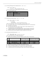
(20) Printing and Feeding the paper by n lines (ESC d n)
Code : [1B]h + [64]h + n
*{0 ≤ n ≤ FF} Data is described in Hex code.
Prints data inside the buffer and feeds paper by n lines.
l Specified line does not remain.
l The beginning of the line is to be considered as the next printing start position.
(21) Generating specified Pulse (ESC p m n1 n2)
Code : [1B]h + [70]h + m + n + n2
* {m = connector pin No. (See table below.)}
{0 ≤ n1 ≤ FF}
{0 ≤ n2 ≤ FF} Data is described in Hex code.
Signals specified by n1, n2 are output to Connector Pin m.
l Bit m (m0) means the followings.
m0
Condition
0
Drawer kick No. 2 pin
1
Drawer kick No. 5 pin
l ON time is considered as n1 x 2ms and OFF time as n2 x 2ms.
l When m is out of the defined range, n1, n2 are discarded, where no signals are output.
l Drive duty of Drawer is shown below:
ON time
0.2
ON time + OFF time
≤
(Take OFF time as being 4 times or more longer than ON time.)
(22) Selecting Character Code Table (ESC t n)
Code : [1B]h + [74]h + n
* {0 ≤ n ≤ 1} Data is described in Hex code.
Selecting Page n on the character code table:
l "n" means the followings.
n (Hex)
Condition
0
IBM Character #2
1
Japanese Character
l The initial value of n is specified by dip switch setting. (DS1-5.6.7)
(Other than Japanese character is specified, IBM #2 is specified.)
CITIZEN
53
iDP-3210 User’s Manual
(23) Transmitting the printer status (ESC v)
Code : [1B]h + [76]h
Current printer status is transmitted..
l Status sent out consists of 1 byte whose content is as in the table below.
l In DTR/DSR control, after receptible state of the host (DSR signal being in SPACE state)
is confirmed, only 1 byte is transmitted. In XON/XOFF control, DSR signal state not being
confirmed, only 1 byte is transmitted.
l In DTR/DSR control, when the host is in unreceptible state(DSR signal being in
MARK state), it waits until receptible state is created.
VALUE
BIT
FUNCTION
0
1
0
Not defined
1
Not defined
2
Paper end
With paper
Without paper
3
Not defined
4
Not used
Fixed to 0
5
Not defined
6
Not defined
7
Not defined
Remarks. This command is valid only for serial interface model.
(24) Transmitting the status of Peripheral Equipment (ESC u n)
Code : [1B]h + [75]h + n
* {n = 0}
Current status of connector pin No.3 is transmitted.
l "n" means the followings.
n (Hex)
0
l
l
l
l
Condition
Drawer Kick Connector No. 3
Status transmitted consists of 1 byte whose content is as in the table below.
Any equipment has not been connected to this connector, Bit 0 of n is always "1".
In DTR/DSR control, after receptible state of the host (DSR signal being in SPACE state) is
confirmed, only 1 byte is transmitted. Further, in XON/ XOFF control, DSR signal state
not being confirmed, only 1 byte is transmitted.
In DTR/DSR control, when the host is unreceptible state (DSR signal being in MARK state),
it keeps waiting until receptible state is created.
VALUE
BIT
FUNCTION
0
0
Level of pin No. 3
“L”
1
Not defined
2
Not defined
3
Not defined
4
Not used
Fixed to 0
5
Not defined
6
Not defined
7
Not defined
(Remarks) This command is valid only for serial interface model.
CITIZEN
54
1
“H”
-
iDP-3210 User’s Manual
(25) specifying/Canceling Inverted Characters
Code : [1B]h + [7B]h + n
* {0 ≤ n ≤ FF} Data is described in Hex code.
Specifying/canceling inverted characters.
l "n" is valid only for the lowest bit (n0).
l Bit n (n0) means the followings.
n0
0
1
l
l
l
Condition
Canceling inverted characters.
Specifying inverted characters.
This is valid only when this is specified at the beginning of a line.
The printing example is shown below.
The initial value of n is "0".
When inverted characters
have been canceled:
When inverted characters
have been assigned:
Paper feed direction
CITIZEN
55
iDP-3210 User’s Manual
(26) Specifying/Canceling 90°-right- turned Characters (ESC V n)
Code : [1B]h + [56]h + n
*{0 ≤ n ≤ 1} Data is described in Hex code.
Specifying/canceling characters 90°-right- turned character.
l No underlines are attached to 90°-right- turned characters .
l "n" means the followings.
n (Hex)
0
1
l
Condition
Canceling 90° -right- turned Characters
Specifying 90° -right- turned Characters
The initial value of n is "0".
(27) Specifying Absolute Positions (ESC $ n1 n2)
Code : [1B]h + [24]h + n1 + n2
* {0 ≤ n1 ≤ FF}
{0 ≤ n2 ≤ 1} Data is described in Hex code.
The printing start position is specified in the number of dots from the beginning of line.
l
l
The number of dots is divided by 256, whose quotient is taken as n2 and the residual as n1.
Therefore, the printing start position is equal to n1 + n2 x 256 from the beginning of line..
Specifying beyond the line end is ignored.
(28) Specifying Relative Positions (ESC ¥ n1 n2)
Code : [1B]h + [5C]h + n1 + n2
* {0 ≤ n1 ≤ FF}
{0 ≤ n2 ≤ FF} Data is described in Hex code.
The printing start position is specified in the number of dots from the current
position.
l Rightward direction is taken as plus and leftward direction as minus.
l To specify N dot in minus (left) direction, use a complement of N for assignment.
- N dots = 65536 - N
l The number of dots is divided by 256, whose quotient is taken as n2 and the residual as n1.
l Specifying exceeding the end of line is ignored.
CITIZEN
56
iDP-3210 User’s Manual
(29) Bar Code Printing (GS k n Dn NUL)
Code : [1D]h + [6B]h + n + Dn + [00]h
* {0 ≤ n ≤ 7} Data are described in Hex code.
Specifying a type of bar code and printing bar codes.
l The beginning of line is considered as the next printing start position.
l Depending on the value of n, the following bar code can be selected.
l Dn indicates a character code to be printed.
n (Hex)
0
1
2
3
4
5
6
7
Bar Code System
UPC-A
UPC-E
JAN13 (EAN)
JAN 8 (EAN)
CODE 39
ITF
CODABAR
CODE 128
Maximum Columns
15
26
19
17
*maximum columns in the printer
l Data, when being held in the print buffer, are ignored.
l When the character code Dn cannot be printed, the data following after this is printed as ordinary
print data.
l When a bar code whose number of characters to be printed is fixed has been selected,
the number of characters have to be always made equal to the number of characters to be printed.
When the horizontal direction exceeds one line length, the excess part is not printed.
(30) Selecting Bar Code width (GS w n)
Code : [1d]H + [77]H + N
* {2 ≤ n ≤ 4} Data is described in Hex code.
Selecting bar code width.
l The initial value of this width is "3".
(31) Selecting Bar Code Height (GS h n)
Code : [1d]H + [68]H + N
* {1 ≤ n ≤ FF} Data is described in Hex code.
Selecting bar code height.
l "n" indicates the number of dots in vertical direction.
l The initial value of n is "162".
CITIZEN
57
iDP-3210 User’s Manual
(32) Selecting Printing Position of HRI Characters (GS H n)
Code : [1d]H + [48]H + N
* {0 ≤ n ≤ 3} Data is described in Hex code.
Selecting printing position of HRI characters for printing bar codes.
l "n" means the followings.
n (Hex)
Printing Position
0
No printing
1
Above the bar code
2
Below the bar code
3
Both above and below the bar code
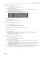
l The initial value of n is "0".
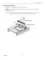
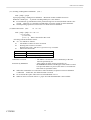
(33) Defining Download Bit Image (GS * n1 n2 Dn)
Code : [1D]h + [2A]h + n1 + n2 Dn
* {1 ≤ n1 ≤ FF}
{1 ≤ n2 ≤ 48}
{n1 x n2 ≤ 1311} Data is described in Hex code.
Defines downloading bit images of the number of dots specified by n1/n2.
l The numbers of dots are n1 x 8 in horizontal direction and n2 x 8 in vertical direction.
l Dn indicates bit image data.
l The download bit image thus defined remains effective until redefinition, ESC @
execution, ESC &, or power OFF takes place.
l A download character and a download bit image cannot be defined simultaneously.
With this command executed, defined content of a download character is cleared.
l Relations between the bit image data and the dot defined are shown below:
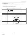
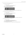
(34) Printing Download Bit Image (GS / m)
Code : [1D]h + [2F]h + m
* {0 ≤ m ≤ 3} Data is described in Hex code.
Prints download bit images in a mode specified by m.
l Modes can be selected by m are shown table for selection with m are shown below.
l
l
l
l
CITIZEN
m
MODE NAME
0
1
2
3
Normal mode
Double wide mode
double high mode
Double wide/double high mode
DOT DENSITY IN
DOT DENSITY IN
VERTICAL DIRECTION HORIZONTAL DIRECTION
156 DPI
154 DPI
156 DPI
77 DPI
78 DPI
154 DPI
78 DPI
77 DPI
When data exist inside the print buffer, this command is ignored.
When a download bit image has not been defined, this command is ignored.
A portion of a download bit image exceeding one line length is not printed.
A download character and a download bit image cannot be defined simultaneously.
58
iDP-3210 User’s Manual
(35) Starting / Ending Macro Definition (GS :)
Code : [1D]h + [3A]h
Specifying starting / ending macro definition. Maximum content available for macro
definition is 2048 bytes. A portion exceeding 2048 bytes is not defined.
l Even with ESC @ (initialization of the printer) having been executed, defined content is not
cleared. Therefore, it is possible to include ESC @ into the content of macro definition.
l Normal printing operation is carried out even while in macro definition
(37) Macro Execution (GS^
n1 n2 n3)
Code : [1D]h + [5E]h + n1 + n2 + n3
* {0 ≤ n1 ≤ FF}
{0 ≤ n2 ≤ FF}
{0 ≤ 3 ≤ 1} Data is described in Hex code.
Executing contents defined in macro.
l "n1 - n3" indicate as follows:
n1 : The number of times of macro execution
n2 : Waiting time on macro execution
Waiting time of n2 x 100 msec is given for every execution.
n3 : Macro execution mode
n3
0
1
Mode
Continuous execution
Execution by the paper feed SW
Continuous execution
: The Macro is executed n1 times continuously at the time
intervals specified by n2.
Execution by FEED SW
: After waiting for lapse of time specified by n2,
the ERROR LED flickers and the paper feed switch is waited
to be pressed. When it is pressed, the macro is executed once.
This action is repeated n1 times.
l When this command is received while in macro definition, suspension of macro definition
is indicated. At this time, the defined content is cleared.
l No execution takes place when macro is held undefined or n1=0.
l While in macro execution with n3=1, paper feed with the FEED SW is not available.
CITIZEN
59
iDP-3210 User’s Manual
(38) Data Input Control (ESC = n)
Code : [1B]h + [3D]h + n
* {0 ≤ n ≤ FF} Data is described in Hex code.
Selecting equipment in which data input from the host is effective.
l Each bit of n indicates as follows:
VALUE
BIT
EQUIPMENT
0
1
0
Printer
Invalid
Valid
1
Not defined
2
Not defined
3
Not defined
4
Not defined
5
Not defined
6
Not defined
7
Not defined
l When the printer has not been selected, this printer abandons all received data until it
is selected by this command.
l Even when the printer has not been selected, it can become BUSY state through printer
operation.
l The initial value of n is "1".
(39) Aligning the characters (ESC a n)
Code : [1b]h + [61]h + n
* {0 ≤ n ≤ 2} Data is described in Hex code.
All the printed data within one line are aligned in the specified position.
l Depending on n value, positional alignment is carried out as in the table below:
l
l
n (Hex)
POSITION
0
Left end alignment
1
Centering
2
Right end alignment
This is valid only when n is inputted at the beginning of line.
The initial value of n is "0".
(40) Full Cut (ESC i)
Code : [1B]h + [69]h
Full cutting of paper is performed.
l This is valid only when n is inputted at the beginning of line.
(41) Partial Cut (ESC m)
Code : [1B]h + [6D]h
Partial cutting of paper is carried out.
l This is valid only when n is inputted at the beginning of line.
CITIZEN
60
iDP-3210 User’s Manual
10 CHARACTER CODE TABLE
10.1 International (IBM Character #2)
CITIZEN
61
iDP-3210 User’s Manual
10.2 International Character Code Table
CITIZEN
62
iDP-3210 User’s Manual
Appendix 1 Outline Drawing
1.1Outler Drawing of Printer (Model : iDP-3210)
CITIZEN
63
iDP-3210 User’s Manual
1.2Outer Drawing of AC Adapter (Model : 30AD)
CITIZEN
64
iDP-3210 User’s Manual
Appendix 2 Block Diagram
CITIZEN
65