1
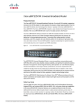
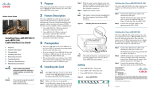
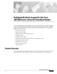
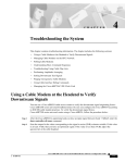
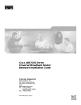
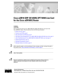
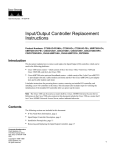
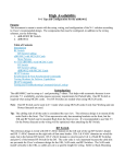
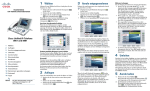
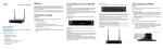
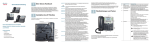
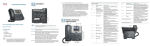
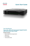
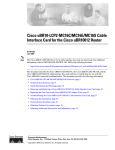
QUICK START GUIDE
2 Feature Description
The Cisco uBR-MC28 cable interface line card
improves RF performance, supports spectrum
management, increases system performance and
supports online insertion and removal (OIR).
The line card is available in three configurations:
• Cisco uBR-MC28U—with an onboard
upconverter and green end tabs
Tighten the captive screws.
Note
The captive screws provide grounding for
the electromagnetic interference (EMI)
shielding.
Figure 1
Warning
Only trained and qualified
personnel should be allowed to
install, replace, or service this
product; and should be properly
grounded before handling this
ESD-sensitive product.
88984
4 Installing the Card
Step 1
The uBR-E-28U is an entry-level version of
MC28U, for the uBR7225 chassis. The
extra guide pins in the line card prevents it
from being plugged into a different
chassis.
Make sure that you are grounded.
7
US
6
US
5
US
4
US
3
US
2
US
1
LE
AB
88983
Step 1
Connect the downstream (DS) cables to
the DS ports (DS0–DS1). RF DS port rings
and end tabs are green (slate blue in the
case of E-28U card). See Figure 5.
Step 2
Connect the upstream cables to the US
ports (US0–US7).
0-R
DS
F
1-R
The cable interface line card
insertion/removal method is the same for
all Cisco uBR7200 series routers.
Add RF attenuators as required to get the
correct IF output. Insert the attenuator
between the DS IF output cable and the
upconverter. See Figure 3.
Americas Headquarters
Cisco Systems, Inc.
170 West Tasman Drive
San Jose, CA 95134-1706
USA
http://www.cisco.com
Tel: 408 526-4000
800 553-NETS (6387)
Fax: 408 527-0883
Cabling
Caution
Connect the DS cables to the DS ports on
the card (DS0–DS1).
IF DS port rings and end tabs are yellow.
See Figure 3.
F
EN
AB
LE
D
DS
Step 1
Step 2
Note
Note
7
Related Documentation
6
8
US
Technical Specifications
5
7
US
Troubleshooting
4
6
uBR - MC28U
US
Removing the Card
• If you are replacing a Cisco uBR-MC28C card
with a Cisco uBR-MC28U/X/E card, you must
reconfigure the card. We strongly recommend
that you reload the Cisco 7200 series router
when replacing a cable interface line card with
a card of a different type.
3
5
• The Cisco NPE-400 or Cisco NPE-G1 or Cisco
NPE-G2 must be used with this card.
US
Installing the Card
3 Prerequisites
2
4
The Cisco uBR-MC28U/E-28U line card has an
onboard upconverter. To cable the card:
The Cisco uBR-MC28X line card does not have an
onboard upconverter. The card may require up to
10 dB of attenuation due to a higher IF output
power (higher then legacy Cisco line cards). To
cable the card:
US
Prerequisites
Domain1
Cabling the Cisco uBR-MC28X
1
3
DS
1-R
F
Cabling the Cisco uBR-MC28U/E-28U
• Cisco uBR-E-28U—with an onboard
upconverter and slate blue end tabs
US
Feature Description
Domain 0
Installing the Card in the Chassis
0
2
DS
0-R
F
D
Step 4
US
Purpose
uBR - MC28U
With the metal carrier aligned in the slot
guides (see Figure 1), gently slide the card
into the card slot until you can feel it
seated in the backplane connectors.
US
1
Domain 0 and Domain 1
EN
Step 3
• Cisco uBR-MC28X—without an onboard
upconverter and with yellow end tabs
Installing Cisco uBR-MC28U/X
and uBR-E-28U Cable Interface
Line Cards
Figure 2
US
Use both hands to grasp the card by its
metal carrier edges and align the card with
the slot guides, component side up.
0
This quick start guide shows you how to install a
Cisco uBR-MC28 cable interface line card in the
Cisco uBR7200 series router.
Step 2
US
1 Purpose
Do not mix upstream (US) ports in
domain 0 with US ports in domain 1
(see Figure 2).
Cisco, Cisco Systems, the Cisco logo, and the Cisco Systems logo are registered trademarks or
trademarks of Cisco Systems, Inc. and/or its affiliates in the United States and certain other
countries. All other trademarks mentioned in this document or Website are the property of their
respective owners. The use of the word partner does not imply a partnership relationship between
Cisco and any other company. (0705R)
© 2009 Cisco Systems, Inc. All rights reserved.
Printed in the USA on recycled paper containing 10% postconsumer waste.
DOC-7815730=
OL-19040-01
7
US
6
US
5
US
4
US
US
3
uBR - MC28U
2
Place the card on an antistatic surface with
its components facing upward.
DS
0-R
F
LE
AB
Table 1
5 Removing the Card
6 Troubleshooting
To prevent the alarms from activating,
administratively shut down the card using the
shutdown command in interface configuration
mode before removing it from the chassis.
1. Make sure that the card is securely seated in
the chassis.
Step 1
Make sure that you are properly
grounded.
Step 2
Disconnect all the cables from the cable
interface line card.
Step 3
Unscrew the captive installation screws on
the faceplate.
Figure 4
Removing the Card from the Chassis
If the captive screws do not tighten all the way,
the card is not properly seated in the chassis or
backplane. Carefully pull the card halfway out
of the slot, reinsert it, and tighten the captive
installation screws.
Caution
A partially seated line card can cause
the router to reboot.
2. Are all enabled LEDs on? If yes, the system is
operational.
88982
a. If the card has been enabled and
configured for operations, the enabled
LED remains on.
1-R
F
D
DS
F
EN
AB
0-R
LE
7
US
6
5
US
US
4
US
3
2
US
US
1
US
0
US
DS
LEDs/Status
LED/Status
Description
ENABLED—green
ENABLED—off
Card operating normally
Card not enabled
US—green
US—off
Upstream enabled
Upstream not enabled
DS—green
DS—off
Downstream enabled
Downstream not enabled
7 Technical Specifications
If no, check the following possibilities:
uBR - MC28U
Downstream
LEDs
DS0-DS1
b. If a port is enabled but its enabled LED is
still off, check if the card has pulled away
from the router. Reseat the card in its slot.
(Do not have to turn off the system power
to do this.} After the system reinitializes
the interfaces, the enabled LED on the
card should come on.
Table 2
Technical Specifications
Description
Order Num/ Specifications
Cisco uBR-MC28U,
with upconverter
UBR-MC28U,
UBR-MC28U=
Cisco uBR-MC28X,
without upconverter
UBR-MC28X,
UBR-MC28X=
Cisco uBR-E-28U,
with upconverter
UBR-E-28U
Blank covers
UBR-MC-COVER=
Weight—MC28U/E28U
Weight—MC28X
6 lbs (2.72 kg)
4.75 lbs (2.15 kg)
UBR-E-28U=
Power consumption
Step 4
Grasp the handle and carefully pull the
card out of its slot (see Figure 4).
MC28U/E-28U
MC28X
80 Watts (273 BTU/h)
50 Watts (170.6 BTU/h)
88985
Cable
Order Num/ Specifications
Output—MC28U/E28U
Output—MC28X
+50 to 61 dBmV at RF
Downstream
(DS0–DS1)
EN
Upstream
LEDs
US0-US7
If the card is being returned to the factory,
immediately place it in a static shielding
bag and proper packaging for protection.
Note
Attenuator
Description
+42 dBmV at IF (+/-2 dB)
Upstream (US0–US7) QPSK 8–, 16–, 32–,
64–QAM
DS
1-R
F
D
Connector
Upconverter
Technical Specifications (continued)
Modulation
Enabled
LED
US
D
LE
EN
AB
Step 5
Table 2
LEDs
1
7
+42 dBmV
Figure 5
US
DS
1-IF
DS
0-IF
US
6
US
5
US
4
US
3
US
2
US
1
US
US
0
uBR - MC28X
Always handle the card by the carrier
edges and handle; never touch the
cable interface line card’s components
or connector pins. For proper cooling
and airflow, always install a line card
cover in an empty line card slot.
0
Inserting an Attenuator
88993
Figure 3
Caution
3. If the enabled LED remains off after the above
checks, it is likely that the system has detected
a processor hardware failure. Go to the Cisco
TAC website http://www.cisco.com/tac for
further information and help.
US
Connect the US cables to the US ports on
the card (US0–US7). All US ports are light
blue.
Step 3
64–QAM, 256–QAM
RF output power range—50 to 61 dBmV
Frequency range
Upstream
Downstream
5–65 MHz
70–860 MHz
The Cisco uBR-MC28U/X/E-28U line card is
compatible with most cable systems worldwide,
including but not limited to—Asia Pacific,
Europe, and the Americas. See Cisco IOS release
notes for more information.
8 Related Documentation
For more information, refer to the following at
Cisco.com:
• Cisco uBR7200 Universal Broadband Series
Hardware Installation Guide
• Cisco uBR7200 Series Cable Interface Line
Card Hardware Installation Guide
• Cisco uBR7200 Series Universal Broadband
Routers
• For the 1–year warranty information, visit the
following URL:
http://www.cisco.com/en/US/products/prod_w
arranties_listing.html