1
Cisco SCE8000 Installation and
Configuration Guide
Release 3.1.7
December, 2008
Americas Headquarters
Cisco Systems, Inc.
170 West Tasman Drive
San Jose, CA 95134-1706
USA
http://www.cisco.com
Tel: 408 526-4000
800 553-NETS (6387)
Fax: 408 527-0883
Customer Order Number:
Text Part Number: OL-16478-02
THE SPECIFICATIONS AND INFORMATION REGARDING THE PRODUCTS IN THIS MANUAL ARE SUBJECT TO CHANGE WITHOUT NOTICE. ALL
STATEMENTS, INFORMATION, AND RECOMMENDATIONS IN THIS MANUAL ARE BELIEVED TO BE ACCURATE BUT ARE PRESENTED WITHOUT
WARRANTY OF ANY KIND, EXPRESS OR IMPLIED. USERS MUST TAKE FULL RESPONSIBILITY FOR THEIR APPLICATION OF ANY PRODUCTS.
THE SOFTWARE LICENSE AND LIMITED WARRANTY FOR THE ACCOMPANYING PRODUCT ARE SET FORTH IN THE INFORMATION PACKET THAT
SHIPPED WITH THE PRODUCT AND ARE INCORPORATED HEREIN BY THIS REFERENCE. IF YOU ARE UNABLE TO LOCATE THE SOFTWARE LICENSE
OR LIMITED WARRANTY, CONTACT YOUR CISCO REPRESENTATIVE FOR A COPY.
The Cisco implementation of TCP header compression is an adaptation of a program developed by the University of California, Berkeley (UCB) as part of UCB’s public
domain version of the UNIX operating system. All rights reserved. Copyright © 1981, Regents of the University of California.
NOTWITHSTANDING ANY OTHER WARRANTY HEREIN, ALL DOCUMENT FILES AND SOFTWARE OF THESE SUPPLIERS ARE PROVIDED “AS IS” WITH
ALL FAULTS. CISCO AND THE ABOVE-NAMED SUPPLIERS DISCLAIM ALL WARRANTIES, EXPRESSED OR IMPLIED, INCLUDING, WITHOUT
LIMITATION, THOSE OF MERCHANTABILITY, FITNESS FOR A PARTICULAR PURPOSE AND NONINFRINGEMENT OR ARISING FROM A COURSE OF
DEALING, USAGE, OR TRADE PRACTICE.
IN NO EVENT SHALL CISCO OR ITS SUPPLIERS BE LIABLE FOR ANY INDIRECT, SPECIAL, CONSEQUENTIAL, OR INCIDENTAL DAMAGES, INCLUDING,
WITHOUT LIMITATION, LOST PROFITS OR LOSS OR DAMAGE TO DATA ARISING OUT OF THE USE OR INABILITY TO USE THIS MANUAL, EVEN IF CISCO
OR ITS SUPPLIERS HAVE BEEN ADVISED OF THE POSSIBILITY OF SUCH DAMAGES.
CCDE, CCENT, Cisco Eos, Cisco HealthPresence, the Cisco logo, Cisco Lumin, Cisco Nexus, Cisco StadiumVision, Cisco TelePresence, Cisco WebEx, DCE, and Welcome
to the Human Network are trademarks; Changing the Way We Work, Live, Play, and Learn and Cisco Store are service marks; and Access Registrar, Aironet, AsyncOS,
Bringing the Meeting To You, Catalyst, CCDA, CCDP, CCIE, CCIP, CCNA, CCNP, CCSP, CCVP, Cisco, the Cisco Certified Internetwork Expert logo, Cisco IOS,
Cisco Press, Cisco Systems, Cisco Systems Capital, the Cisco Systems logo, Cisco Unity, Collaboration Without Limitation, EtherFast, EtherSwitch, Event Center, Fast Step,
Follow Me Browsing, FormShare, GigaDrive, HomeLink, Internet Quotient, IOS, iPhone, iQuick Study, IronPort, the IronPort logo, LightStream, Linksys, MediaTone,
MeetingPlace, MeetingPlace Chime Sound, MGX, Networkers, Networking Academy, Network Registrar, PCNow, PIX, PowerPanels, ProConnect, ScriptShare, SenderBase,
SMARTnet, Spectrum Expert, StackWise, The Fastest Way to Increase Your Internet Quotient, TransPath, WebEx, and the WebEx logo are registered trademarks of
Cisco Systems, Inc. and/or its affiliates in the United States and certain other countries.
All other trademarks mentioned in this document or website are the property of their respective owners. The use of the word partner does not imply a partnership relationship
between Cisco and any other company. (0812R)
Any Internet Protocol (IP) addresses used in this document are not intended to be actual addresses. Any examples, command display output, and figures included in the
document are shown for illustrative purposes only. Any use of actual IP addresses in illustrative content is unintentional and coincidental.
Cisco SCE8000 Installation and Configuration Guide
© 2008 Cisco Systems, Inc. All rights reserved.
C O N T E N T S
About this Guide
CHAPTER
1
ix
Cisco Service Control Overview
1-1
Cisco Service Control Solution 1-1
Service Control for Broadband Service Providers
Cisco Service Control Capabilities
SCE Platform Description
1-2
1-3
Management and Collection 1-5
Network Management 1-5
Subscriber Management 1-6
Service Configuration Management
Data Collection 1-6
CHAPTER
2
1-1
1-6
Introduction to the Cisco SCE8000 Platform
Information About the SCE Platform
2-1
2-1
Service Control Module (SCE8000-SCM-E)
2-2
Introduction to SIPs and SPAs 2-4
SPA Interface Processors 2-4
Specifying the SIP Subslot Location for a SPA 2-5
Shared Port Adapters 2-5
Modular Optics 2-6
XFP Connections 2-6
The SCE8000-SIP 2-7
The 1-Port 10GBE SPA Interface Module 2-7
The Cisco SCE8000 Optical Bypass 2-8
Optical Bypass Functionality 2-9
Optical Bypass Module Connectivity 2-9
Optical Bypass Module (OPB-SCE8K) 2-9
Optical Bypass Module Specifications 2-11
Fan Assembly 2-11
Power Supplies 2-12
Power Supply Cooling 2-13
Load Sharing 2-13
Checking the Shipping Container Contents
2-13
Cisco SCE8000 Installation and Configuration Guide, Rel 3.1.7
OL-16478-02
i
Contents
Cisco SCE8000 Component List
Cisco SCE8000 Installation Checklist
CHAPTER
3
2-14
2-15
Cisco SCE8000 Topology and Topology-Related Parameters
The Cisco SCE8000 Platform
Topology Considerations
3-1
3-1
3-1
Physical Topologies 3-3
SCE8000 Interface Numbering 3-3
Single Cisco SCE8000 Topologies 3-3
Single Link: Inline Topology 3-4
Dual link: Inline Installation 3-4
Single Link: Receive-only Topology 3-5
Dual Link: Receive-Only Topology 3-5
Dual Cisco SCE8000 Topology (Cascade) 3-6
Multi-Gigabit Service Control Platform (MGSCP) Topology
Type of SCE Platform Redundancy 3-8
Redundant Cisco 7600 Series Router 3-8
3-7
Link Continuity 3-9
Internal Bypass Mechanism 3-9
External Optical Bypass 3-9
Topology-Related Parameters 3-11
Connection Mode Parameter 3-11
Physically Connected Links Parameter
Priority 3-12
On-Failure Mode Parameter 3-12
3-12
Asymmetric Routing Topology 3-13
Asymmetric Routing and Other Service Control Capabilities
CHAPTER
4
Installing the Cisco SCE8000 Chassis
3-13
4-1
Preparing for Installation 4-2
Safety 4-2
Site Requirements 4-2
Preventing Electrostatic Discharge Damage
Environmental Requirements 4-3
Power Requirements 4-3
Power Connection Guidelines 4-4
AC-Powered Systems 4-4
DC-Powered Systems 4-10
Site Planning Checklist 4-11
4-3
Cisco SCE8000 Installation and Configuration Guide, Rel 3.1.7
ii
OL-16478-02
Contents
Installing the Cisco SCE8000 Chassis in the Rack 4-12
Unpacking the Cisco SCE8000 Chassis 4-12
Installation Guidelines 4-12
Required Tools 4-13
Installing the Chassis Brackets 4-13
Installing the Chassis in the Rack 4-14
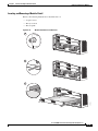
Installing an Optical Bypass Module 4-15
Connecting the System Ground 4-16
Required Tools and Equipment 4-17
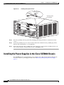
Installing the Power Supplies in the Cisco SCE8000 Chassis
CHAPTER
5
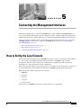
Connecting the Management Interfaces
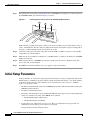
How to Set Up the Local Console
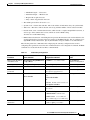
Initial Setup Parameters
5-1
5-1
5-2
Connecting the Management Interface 5-4
How to Cable the Management Port 5-4
How to Verify Management Interface Connectivity
CHAPTER
6
4-18
Cabling the Line Ports and Completing the Installation
5-5
6-1
Connecting the Line Ports to the Network 6-1
Single Link: Inline Topology 6-2
Single Link: Receive-only Topology 6-2
Dual Link: Single Cisco SCE8000 Topologies 6-2
Dual Link: Two Cisco SCE8000s Topology 6-3
Multi-Gigabit Service Control Platforms (MGSCP) Topologies
The Optical Bypass Module 6-8
Optical Bypass Module Connectivity
6-4
6-8
Cabling the 10GBE Line Interface Ports 6-9
Fiber Specifications 6-10
Optical Device Maintenance 6-10
How to Cable the 10GBE Line Interface Ports 6-10
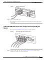
Cabling the 10GBE Line Interface Ports: Using the External Optical Bypass Module
Testing Connectivity: Examining Link LEDs and Counters 6-13
Examining the LEDs 6-13
How to View the Ten Gigabit Ethernet Port Status 6-13
How to View the Ten Gigabit Ethernet Counters 6-13
How to View the User Log Counters 6-14
How to Load and Activate a Service Control Application
6-11
6-14
Cisco SCE8000 Installation and Configuration Guide, Rel 3.1.7
OL-16478-02
iii
Contents
Cascaded Systems 6-15
How to Install a Cascaded System 6-15
CLI Commands for Cascaded Systems 6-16
Topology-Related Parameters for Redundant Topologies
How to Configure the Connection Mode 6-16
How to Set the Link Mode 6-17
Monitoring the System 6-18
CHAPTER
7
Basic Cisco SCE8000 Platform Operations
6-16
7-1
Starting the Cisco SCE8000 Platform 7-1
Checking Conditions Prior to System Startup 7-1
Performing Complex Configurations 7-2
Starting the System and Observing Initial Conditions 7-2
What to Do Next 7-2
Final Tests 7-3
Verifying Operational Status 7-3
Viewing the User Log Counters 7-3
Viewing the Ten Gigabit Ethernet Port Status 7-4
Viewing the Ten Gigabit Ethernet Counters 7-4
Managing Cisco SCE8000 Configurations 7-5
Viewing Configurations 7-5
Saving or Changing the Configuration Settings 7-6
Example for Saving or Changing the Configuration Settings
Restoring a Previous Configuration 7-8
Example for Restoring a Previous Configuration 7-8
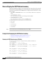
How to Display the SCE Platform Version Information 7-9
Example for Displaying the SCE Platform Version Information
7-7
7-9
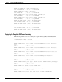
How to Display the SCE Platform Inventory 7-12
Examples for Displaying the SCE Platform Inventory 7-12
Displaying the SCE Platform Inventory: FRUs Only 7-12
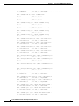
Displaying the Complete SCE Platform Inventory 7-13
How to Display the System Uptime 7-16
Example for Displaying the System Uptime
7-16
Rebooting and Shutting Down the SCE Platform 7-16
Rebooting the SCE Platform 7-16
Examples for Rebooting the SCE Platform 7-16
How to Shut Down the SCE Platform 7-17
Examples for Shutting Down the SCE Platform 7-17
Cisco SCE8000 Installation and Configuration Guide, Rel 3.1.7
iv
OL-16478-02
Contents
CHAPTER
8
Troubleshooting
8-1
Troubleshooting Overview 8-1
Information About Troubleshooting Tools 8-2
CLI Commands for Troubleshooting 8-2
Checking the LEDs 8-4
Problem Solving Using a Subsystems Approach 8-6
Identifying Startup Problems 8-6
Troubleshooting the Power Subsystem 8-7
Troubleshooting the Firmware Package Installation 8-8
Troubleshooting the Management Subsystem 8-8
Troubleshooting the Link Interface Subsystem 8-10
Troubleshooting with the User Log 8-11
The Logging System 8-11
How to Copy the User Log to an External Source 8-12
How to Copy the User Log to an Internal Location 8-12
How to View the User Log 8-12
How to Clear the User Log 8-12
How to View the User Log Counters 8-13
How to View the Non-volatile Counter For the User-file-log Only
Generating a File for Technical Support 8-13
CHAPTER
9
Removal and Replacement Procedures
Safety
8-13
9-1
9-1
Preventing Electrostatic Discharge Damage
Supported Hardware
9-2
9-3
Removing and Replacing the Power Supply 9-3
Required Tools 9-3
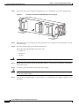
Removing an AC-Input Power Supply 9-3
Installing an AC-Input Power Supply 9-5
Removing a DC-Input Power Supply 9-5
Installing a DC-Input Power Supply 9-7
Removing and Replacing the Fan Assembly
Required Tools 9-10
Removing the Fan Assembly 9-11
Installing the Fan Assembly 9-11
Removing and Replacing Modules
Required Tools 9-12
Handling SIPs 9-13
9-10
9-12
Cisco SCE8000 Installation and Configuration Guide, Rel 3.1.7
OL-16478-02
v
Contents
Installing a Module 9-13
Removing a Module 9-17
Inserting and Removing a Module: Detail
Verifying the Installation 9-20
Removing and Replacing Shared Port Adapters
Required Tools and Equipment 9-22
Laser/LED Safety 9-22
Handling SPAs 9-23
SPA Installation and Removal 9-23
Installing a SPA in a SIP 9-24
Removing a SPA from a SIP 9-24
9-19
9-22
Removing and Replacing the Optical Bypass Module 9-25
Removing the Optical Bypass Module 9-25
Installing the Optical Bypass Module 9-25
Replacing the Optical Bypass Module without Disrupting Traffic on the Link
CHAPTER
A
Using Optical Splitters with 10GBE Links
Supported Configurations A-1
Unsupported Configuration A-2
9-26
A-1
Cisco SCE8000 Installation and Configuration Guide, Rel 3.1.7
vi
OL-16478-02
About this Guide
This preface describes who should read the Cisco SCE8000 Installation and Configuration Guide, how
it is organized, and its document conventions.
This guide is for the networking or computer technician responsible for installing and configuring the
SCE8000 platform on-site. To use this publication, you should be familiar with telecommunications
equipment and installation procedures, as well as electronic circuitry and wiring practices. You should
also have experience as an electronic or electromechanical technician.
This installation guide explains the initial hardware installation and basic configuration procedures for
the SCE8000. It contains procedures for unpacking and installing the device and performing basic
configuration via the setup wizard. After completing the installation and basic configuration procedures
covered in this guide, you will then use the appropriate companion publications to more completely
configure your system.
This guide contains instructions on how to install and run the SCE8000 platform. This guide assumes a
basic familiarity with telecommunications equipment and installation procedures.
Document Revision History
Revision
Cisco Service Control
Release and Date
Change Summary
OL-16478-02
3.1.7
Added explanation of casacade topology and cabling.
December, 2008
OL-16478-01
3.1.6S
June, 2008
First version. New document for new product.
Cisco SCE8000 Installation and Configuration Guide, Rel 3.1.7
OL-16478-02
ix
About this Guide
Organization
The major sections of this guide are as follows:
Chapter Title
Description
1
Cisco Service Control Overview, page 1-1
This chapter provides a brief introduction to
Cisco Service Control.
2
Introduction to the Cisco SCE8000 Platform, This chapter provides a hardware overview of
page 2-1
the SCE8000 platform.
3
Cisco SCE8000 Topology and
Topology-Related Parameters, page 3-1
This chapter describes the possible
deployment topologies of the SCE8000 and
explains how various aspects of the topology
determine the configuration of the system.
4
Installing the Cisco SCE8000 Chassis,
page 4-1
This chapter explains how to install a
SCE8000 platform in the rack and properly
ground it.
5
Connecting the Management Interfaces,
page 5-1
This chapter explains how to connect the
SCE8000 platform to a local console and
perform the initial system configuration via
the setup wizard that runs automatically.
6
Cabling the Line Ports and Completing the
Installation, page 6-1
This chapter provides instructions for cabling
the Gigabit Ethernet ports for both one and
two SCE8000 topologies, and for configuring
Gigabit Ethernet (GBE) interface parameters.
In a topology utilizing two SCE8000s
(cascade), this includes the cascade ports as
well as the line ports.
7
Basic Cisco SCE8000 Platform Operations,
page 7-1
This chapter describes how to start up the
SCE8000 platform, reboot, and shutdown. It
also describes how to manage configurations.
8
Troubleshooting, page 8-1
This chapter provides basic system startup
troubleshooting information.
9
Removal and Replacement Procedures,
page 9-1
This chapter explains the procedures for
removing and replacing the power supplies,
fan trays, and other modules.
A
Using Optical Splitters with 10GBE Links,
page A-1
This appendix supplies important information
regarding supported and not supported optical
splitter configurations in the 10GBE
environment.
Cisco SCE8000 Installation and Configuration Guide, Rel 3.1.7
x
OL-16478-02
About this Guide
Related Publications
Your SCE8000 platform and the software running on it contain extensive features and functionality,
which are documented in the following resources:
•
Cisco CLI software:
– Cisco SCE8000 Software Configuration Guide
– Cisco SCE8000 CLI Command Reference
•
For initial installation and startup information, refer to the Cisco SCE8000 Quick Start Guide.
•
For international agency compliance, safety, and statutory information for wide-area network
(WAN) interfaces for the SCE8000 platform, refer to the Regulatory Compliance and Safety
Information for Cisco SCE8000.
•
For installation and configuration of the other components of the Service Control Management Suite
refer to:
– Cisco SCMS Subscriber Management User Guide
– Cisco SCMS Collection Manager User Guide
– Cisco Service Control Application for Broadband User Guide
– Cisco Service Control Application Reporter User Guide
•
To view Cisco documentation or obtain general information about the documentation, refer to the
Cisco Information Packet that shipped with your SCE8000 platform.
Conventions
This document uses the following conventions:
Convention
Indication
bold font
Commands and keywords and user-entered text appear in bold font.
italic font
Document titles, new or emphasized terms, and arguments for which you supply
values are in italic font.
[ ]
Elements in square brackets are optional.
{x | y | z }
Required alternative keywords are grouped in braces and separated by
vertical bars.
[x|y|z]
Optional alternative keywords are grouped in brackets and separated by
vertical bars.
string
A nonquoted set of characters. Do not use quotation marks around the string or
the string will include the quotation marks.
courier
font
Terminal sessions and information the system displays appear in courier font.
< >
Nonprinting characters such as passwords are in angle brackets.
[ ]
Default responses to system prompts are in square brackets.
!, #
An exclamation point (!) or a pound sign (#) at the beginning of a line of code
indicates a comment line.
Cisco SCE8000 Installation and Configuration Guide, Rel 3.1.7
OL-16478-02
xi
About this Guide
Note
Means reader take note.
Tip
Means the following information will help you solve a problem.
Caution
Timesaver
Warning
Means reader be careful. In this situation, you might perform an action that could result in equipment
damage or loss of data.
Means the described action saves time. You can save time by performing the action described in
the paragraph.
Means reader be warned. In this situation, you might perform an action that could result in
bodily injury.
Obtaining Documentation and Submitting a Service Request
For information on obtaining documentation, submitting a service request, and gathering additional
information, see the monthly What’s New in Cisco Product Documentation, which also lists all new and
revised Cisco technical documentation, at:
http://www.cisco.com/en/US/docs/general/whatsnew/whatsnew.html
Subscribe to the What’s New in Cisco Product Documentation as a Really Simple Syndication (RSS)
feed and set content to be delivered directly to your desktop using a reader application. The RSS feeds
are a free service and Cisco currently supports RSS version 2.0.
Cisco SCE8000 Installation and Configuration Guide, Rel 3.1.7
xii
OL-16478-02
CH A P T E R
1
Cisco Service Control Overview
This chapter provides a general overview of the Cisco Service Control solution. It introduces the Cisco
service control concept and capabilities.
It also briefly describes the hardware capabilities of the service control engine (SCE) platform and the
Cisco specific applications that together compose the complete Cisco service control solution.
•
Cisco Service Control Solution, page 1-1
•
Cisco Service Control Capabilities, page 1-2
•
SCE Platform Description, page 1-3
•
Management and Collection, page 1-5
Cisco Service Control Solution
The Cisco service control solution is delivered through a combination of hardware and specific software
solutions that address various operational and business-related challenges. Service providers can use the
SCE platform to support classification, analysis, and control of Internet and IP traffic.
Service control enables service providers to:
•
Capitalize on existing infrastructure.
•
Analyze, charge for, and control IP network traffic at multigigabit wire line speeds.
•
Identify and target high-margin content-based services and enable their delivery.
As access and bandwidth have become commodities where prices continually fall and profits disappear,
service providers have realized that they must offer value-added services to derive more revenue from
the traffic and services running on their networks.
Cisco service control solutions allow the service provider to capture profits from IP services through
detailed monitoring, precise, real-time control, and awareness of applications as they are delivered.
Service Control for Broadband Service Providers
Service providers of any access technology (DSL, cable, mobile, and so on) targeting residential and
business consumers must find new ways to get maximum leverage from their existing infrastructure,
while differentiating their offerings with enhanced IP services.
The Cisco service control application for broadband adds a layer of service intelligence and control to
existing networks that can:
Cisco SCE8000 Installation and Configuration Guide, Rel 3.1.7
OL-16478-02
1-1
Chapter 1
Cisco Service Control Overview
Cisco Service Control Capabilities
•
Report and analyze network traffic at subscriber and aggregate level for capacity planning
•
Provide customer-intuitive tiered application services and guarantee application service level
agreements (SLAs)
•
Implement different service levels for different types of customers, content, or applications
•
Identify network abusers who are violating the acceptable use policy (AUP)
•
Identify and manage peer-to-peer traffic, NNTP (news) traffic, and spam abusers
•
Enforce the AUP
•
Integrate Service Control solutions easily with existing network elements and business support
systems (BSS) and operational support systems (OSS)
Cisco Service Control Capabilities
The core of the Cisco service control solution is the network hardware device: the Service control engine
(SCE). The core capabilities of the SCE platform, which support a wide range of applications for
delivering service control solutions, include:
•
Subscriber and application awareness—Application-level drilling into IP traffic for real-time
understanding and controlling of usage and content at the granularity of a specific subscriber.
– Subscriber awareness—The ability to map between IP flows and a specific subscriber to
maintain the state of each subscriber transmitting traffic through the SCE platform and to
enforce the appropriate policy on this subscriber’s traffic.
Subscriber awareness is achieved either through dedicated integrations with subscriber
management repositories, such as a DHCP or a RADIUS server, or through sniffing of RADIUS
or DHCP traffic.
– Application awareness—The ability to understand and analyze traffic up to the application
protocol layer (Layer 7).
For application protocols implemented using bundled flows (such as FTP, which is
implemented using Control and Data flows), the SCE platform understands the bundling
connection between the flows and treats them accordingly.
•
Application-layer, stateful, real-time traffic control—The ability to perform advanced control
functions, including granular bandwidth (BW) metering and shaping, quota management, and
redirection, using application-layer, stateful, real-time traffic transaction processing. This requires
highly adaptive protocol and application-level intelligence.
•
Programmability—The ability to quickly add new protocols and adapt to new services and
applications in the service provider environment. Programmability is achieved using the Cisco
Service Modeling Language (SML).
Programmability allows new services to be deployed quickly and provides an easy upgrade path for
network, application, or service growth.
•
Robust and flexible back-office integration—The ability to integrate with existing third-party
systems at the service provider, including provisioning systems, subscriber repositories, billing
systems, and OSS systems. The SCE provides a set of open and well-documented APIs that allows
a quick integration process.
•
Scalable high-performance service engines—The ability to perform all of these operations at wire
speed.
Cisco SCE8000 Installation and Configuration Guide, Rel 3.1.7
1-2
OL-16478-02
Chapter 1
Cisco Service Control Overview
SCE Platform Description
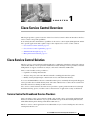
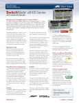
SCE Platform Description
The SCE family of programmable network devices performs application-layer stateful-flow inspection
of IP traffic, and controls the traffic based on configurable rules. The SCE platform is a network device
that uses ASIC components and reduced instruction set computer (RISC) processors to exceed beyond
packet counting and expand into the contents of network traffic. Providing programmable, stateful
inspection of bidirectional traffic flows, and mapping these flows with user ownership, SCE platforms
provide real-time classification of network use. The classification provides the basis of the SCE platform
advanced traffic-control and bandwidth-policing functionality. Where most bandwidth control
functionality ends, the SCE platform provides further control and shaping options, including:
•
Layer 7 stateful wire-speed packet inspection and classification
•
Robust support for more than 600 protocols and applications, including:
– General—HTTP, HTTPS, FTP, Telnet, Network News Transfer Protocol (NNTP), Simple Mail
Transfer Protocol (SMTP), Post Office Protocol 3 (POP3), Internet Message Access Protocol
(IMAP), Wireless Application Protocol (WAP), and others
– Peer-to-Peer (P2P) file sharing—FastTrack-KazaA, Gnutella, BitTorrent, Winny, Hotline,
eDonkey, DirectConnect, Piolet, and others
– P2P VoIP—Skype, Skinny, DingoTel, and others
– Streaming and Multimedia—Real Time Streaming Protocol (RTSP), Session Initiation Protocol
(SIP), HTTP streaming, Real Time Protocol (RTP) and Real Time Control Protocol (RTCP),
and others
•
Programmable system core for flexible reporting and bandwidth control
•
Transparent network and BSS and OSS integration into existing networks
•
Subscriber awareness that relates traffic and usage to specific customers
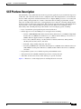
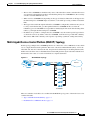
Figure 1-1 illustrates a common deployment of an SCE platform in a network.
Cisco SCE8000 Installation and Configuration Guide, Rel 3.1.7
OL-16478-02
1-3
Chapter 1
Cisco Service Control Overview
SCE Platform Description
Figure 1-1
SCE Platform in the Network
Corporate
Provider
network
PWR A
MNG 1
LINK/
ACTIVE 10/100/
1000
MNG 2
CONSOLE
AUX
LINK/
ACTIVE 10/100/
1000
PWR B
STATUS
BYPASS
Cisco SCE
2000
4xGBE Series
LINK RX
TX
LINK RX
TX
LINK RX
TX
RX
MM
LINK RX
TX
TX
RX
MM
TX
RX
MM
TX
GBE-1
SUB
DSL
Aggregation
device
LINE
NET
RX
MM
TX
Users
Peer network
& Internet
GBE-2
SUB LINE/CASCADE
NET
SCE platform
92764
CMTS
Cisco SCE8000 Installation and Configuration Guide, Rel 3.1.7
1-4
OL-16478-02
Chapter 1
Cisco Service Control Overview
Management and Collection
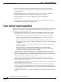
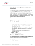
Management and Collection
The Cisco service control solution includes a complete management infrastructure that provides the
following management components to manage all aspects of the solution:
•
Network management
•
Subscriber management
•
Service Configuration management
These management interfaces are designed to comply with common management standards and to
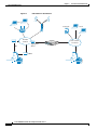
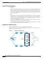
integrate easily with existing OSS infrastructure (Figure 1-2).
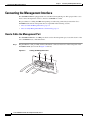
Figure 1-2
Service Control Management Infrastructure
Service
policy and quota
management
Network
management
Provisioning
system
Collection
Manager
XML/RPC
CLI and SNMP
Subscriber
Manager
RDRs
PWR A
MNG 1
LINK/
ACTIVE 10/100/
1000
MNG 2
CONSOLE
AUX
LINK/
ACTIVE 10/100/
1000
PWR B
STATUS
BYPASS
DHCP
or RADIUS
92763
Subscriber info
Cisco SCE
2000
4xGBE Series
LINK RX
TX
LINK RX
TX
LINK RX
TX
RX
MM
LINK RX
TX
TX
RX
MM
TX
RX
MM
TX
GBE-1
SUB
Aggregation
device
LINE
NET
RX
MM
TX
GBE-2
SUB LINE/CASCADE
NET
SCE platform
Router
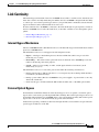
Network Management
The Cisco service control solution provides complete network Fault, Configuration, Accounting,
Performance, Security (FCAPS) Management.
Two interfaces provide network management:
•
Command-line interface (CLI)—Accessible through the Console port or through a Telnet
connection, the CLI is used for configuration and security functions.
•
SNMP—Provides fault management (through SNMP traps) and performance-monitoring
functionality.
Cisco SCE8000 Installation and Configuration Guide, Rel 3.1.7
OL-16478-02
1-5
Chapter 1
Cisco Service Control Overview
Management and Collection
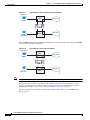
Subscriber Management
Where the Cisco service control application for broadband (SCA BB) enforces policies on different
subscribers and tracks usage on an individual subscriber basis, the Cisco service control management
suite (SCMS) subscriber manager (SM) may be used as middleware software for bridging between OSS
and SCE platforms. Subscriber information is stored in the SM database and can be distributed between
multiple platforms according to actual subscriber placement.
The SM provides subscriber awareness by mapping network IDs to subscriber IDs. It can obtain
subscriber information using dedicated integration modules that integrate with AAA devices, such as
RADIUS or DHCP servers.
Subscriber information may be obtained in one of two ways:
•
Push Mode—The SM pushes subscriber information to the SCE platform automatically upon logon
of a subscriber.
•
Pull Mode—The SM sends subscriber information to the SCE platform in response to a query from
the SCE platform.
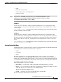
Service Configuration Management
Service configuration management is the ability to configure the general service definitions of a service
control application. A service configuration file containing settings for traffic classification, accounting
and reporting, and control is created and applied to an SCE platform. The SCA BB application provides
tools to automate the distribution of these configuration files to SCE platforms. This standards-based
approach makes it easy to manage multiple devices in a large network.
Service Control provides a GUI to edit and create these files and a complete set of APIs to automate their
creation.
Data Collection
Data collection occurs as follows:
1.
All analysis and data processing functions of the SCE platform result in the generation of Raw Data
Records (RDRs), which the SCE platform forwards using a simple TCP-based protocol
(RDR-Protocol).
2.
RDRs are processed by the Cisco service control management suite collection manager.
3.
The collection manager software is an implementation of a collection system that receives RDRs
from one or more SCE platforms. It collects these records and processes them in one of its adapters.
Each adapter performs a specific action on the RDR.
RDRs contain a variety of information and statistics, depending on the configuration of the system.
Three main categories of RDRs include:
•
Transaction RDRs—Records generated for each transaction, where a transaction is a single event
detected in network traffic. The identification of a transaction depends on the particular application
and protocol.
•
Subscriber Usage RDRs—Records generated per subscriber, describing the traffic generated by that
subscriber for a defined interval.
•
Link RDRs—Records generated per link, describing the traffic carried on the link for a defined
interval.
Cisco SCE8000 Installation and Configuration Guide, Rel 3.1.7
1-6
OL-16478-02
CH A P T E R
2
Introduction to the Cisco SCE8000 Platform
This chapter provides an introduction to the Cisco SCE8000 10GBE platform, the Service Control
hardware component.
•
Information About the SCE Platform, page 2-1
•
Service Control Module (SCE8000-SCM-E), page 2-2
•
Introduction to SIPs and SPAs, page 2-4
•
The SCE8000-SIP, page 2-7
•
The 1-Port 10GBE SPA Interface Module, page 2-7
•
The Cisco SCE8000 Optical Bypass, page 2-8
•
Checking the Shipping Container Contents, page 2-13
•
Cisco SCE8000 Installation Checklist, page 2-15
Information About the SCE Platform
The Service Control Engine (SCE) platform, which is the hardware component of the Cisco Service
Control solution, is designed to support observation, analysis, and control of Internet/IP traffic. The
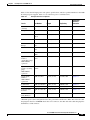
following table summarizes model information for the Cisco SCE8000 platform.
Table 2-1
SCE Platform Model Information
Model number
Cisco SCE8000 10GBE
Link Type
10 Gigabit Ethernet
Number of Ports
2 or 4
Number of Links
1 or 2
The Cisco SCE8000 is a transparent element with 10GBE links service throughput. It can be installed
inline in the network where the entire traffic passes through it or in receive-only mode where it receives
replication of the traffic through SPAN ports or optical splitters.
Cisco SCE8000 Installation and Configuration Guide, Rel 3.1.7
OL-16478-02
2-1
Chapter 2
Introduction to the Cisco SCE8000 Platform
Service Control Module (SCE8000-SCM-E)
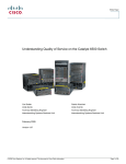
Figure 2-1
FAN STA
TUS
SCM
Cisco SCE8000 Platform
SCE8000-SCM
-E
1
OPTICAL
BYPASS
CONSOLE
PORT 1
10 100
1000
STATUS
OPTICAL
BYPASS
LINK
ACTIVE
SCE8000-SCM
-E
OPTICAL
BYPASS
SCM
AUX
2
SCE8000
EXTENDED
SERVICE
PORT 2
10 100
1000
OPTICAL
BYPASS
CONSOLE
PORT 1
10 100
1000
LINK
ACTIVE
CONTRO
L MODULE
MASTER
SYSTEM
POWER
STATUS
OPTICAL
BYPASS
LINK
ACTIVE
SCE8000-SIP
OPTICAL
BYPASS
SIP
LINK
IVE/
ACT
3
AUX
SCE8000
EXTENDED
SERVICE
PORT 2
10 100
1000
AT
ST
LINK
IVE/
ACT
LINK
ACTIVE
CONTRO
L MODULE
MASTER
SYSTEM
POWER
US
SPA-1X
10GE-L
-V2
LINK
IVE/
ACT
AT
ST
US
SPA-1X
AT
ST
LINK
IVE/
ACT
US
270543
10GE-L
-V2
4
SCE80
SPA-1X
10GE-L
-V2
TX
TX
00-FAN
TX
RX
TX
RX
RX
RX
OPTICAL
BYPASS1
A
B
A
C
C
D
B
D
CTRL
AT
ST
US
SPA-1X
10GE-L
-V2
STATUS
OPB-SCE
8K-MM
TX
TX
TX
RX
TX
RX
RX
RX
OPTICAL
BYPASS2
A
B
A
C
C
D
B
D
CTRL
STATUS
OPB-SCE
8K-MM
The Cisco SCE8000 supports the following network insertion models:
•
single appliance (inline)
•
single appliance (receive-only)
•
cascade configuration
•
MGSCP configuration
The Cisco SCE8000 platform is a 4-slot chassis hosting the following modules:
•
One or two Service Control Modules (SCE8000-SCM-E) that each contain special purpose fast path
chipset, traffic processors and control processor.
•
One SPA Interface Processor card (SCE8000-SIP) that holds up to four SPA 10GBE interface
modules.
•
One optional optical bypass module hosting panel that holds up to two optical bypass modules.
In addition, the Cisco SCE8000 chassis contains two power supply modules in a 1+1 configuration, as
well as a fan tray module.
Service Control Module (SCE8000-SCM-E)
The Cisco SCE8000 contains one or two SCE8000-SCMs located in slots#1 and #2 (the top two slots).
The Service Control module contains ports and LEDs as shown in the following figure and tables.
Figure 2-2
SCE8000-SCM-E
...
SCE8000-SCM-E
SCE8000 EXTENDED SERVICE CONTROL MODULE
STATUS
MASTER
CONSOLE
PORT1
10/100/
1000
LINK/
ACTIVE
SYSTEM POWER
OPTICAL
BYPASS2
AUX
PORT2
10/100/
1000
LINK/
ACTIVE
270874
OPTICAL BYPASS
OPTICAL
BYPASS1
Cisco SCE8000 Installation and Configuration Guide, Rel 3.1.7
2-2
OL-16478-02
Chapter 2
Introduction to the Cisco SCE8000 Platform
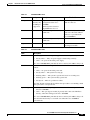
Service Control Module (SCE8000-SCM-E)
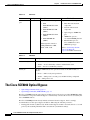
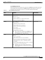
Table 2-2
SCE8000-SCM-E Ports
Port
Quantity
Description
GBE port
2
Gigabit Ethernet RJ-45 ports for A LAN using a GBE cable with
an RJ-45 connector.
management of the Cisco
SCE8000.
Currently only
one GBE port
is supported.
CLI designation: interface
GigabitEthernet 1/1, 1/2.
Console
1
RS-232 RJ-45 port for use by
technicians
AUX
1
RS-232 RJ-45 port used by
technicians
Bypass
2
RJ-11 port
Table 2-3
LEDs
Power
Connect This Port To…
A local terminal (console) using
an RS-232 cable with an RJ-45
connector, as provided in the
Cisco SCE8000 kit.
The Control connector on the
optical bypass module.
SCE8000-SCM-E LEDs
Description
•
Steady green — Installed power supplies are functioning normally.
•
Steady amber — Only one power supply is functioning normally.
•
Unlit — No power from either power supply.
On a slave SCE8000-SMC_E module (in the second slot), this LED is always off.
Status
The Status LED indicates the operational status of the Cisco SCE8000 system, as
follows:
•
Unlit — No power from either power unit.
•
Steady amber — The system is booting up.
•
Flashing amber — The system is operational, but is in a warning state.
•
Flashing green — The system is fully operational.
•
Steady red — There is a problem or failure
Note that Alarms are hierarchical: Failure takes precedence over Warning, which
takes precedence over Operational.
Optical Bypass
•
Steady amber — The optic bypass module has been directed to pass traffic via
the Cisco SCE8000.
•
Unlit — The optic bypass module (if present) will connect the link fibers
directly, and traffic will bypass the Cisco SCE8000.
On a slave SCE8000-SMC_E module (in the second slot), this LED is always off.
Note that this functionality is consistent even when the Cisco SCE8000 is
powered down.
Cisco SCE8000 Installation and Configuration Guide, Rel 3.1.7
OL-16478-02
2-3
Chapter 2
Introduction to the Cisco SCE8000 Platform
Introduction to SIPs and SPAs
Table 2-3
SCE8000-SCM-E LEDs
LEDs
Description
Master
Indicates the master Service Control module
Mng interface
•
Steady green — Master Service Control module
•
Unlit — Slave Service Control module
The Mng interface LEDs indicate the operational status of the Cisco SCE8000
out-of-band LAN-based management port, as follows:
•
Link/Active
Steady green — Port link is up
Flashing green — Activity on the port link
Unlit — Port link is down
•
Speed
Unlit — Port is set to 10Mbps
Steady green — Port is set to 100 Mbps
Steady amber — Port is set to 1000 Mbps
On a slave SCE8000-SMC_E module (in the second slot), this LED is always off.
Introduction to SIPs and SPAs
SIPs and SPAs are a new carrier card and port adapter architecture used to increase modularity,
flexibility, and density across Cisco Systems routers for network connectivity. This section describes the
SIPs and SPAs and provides some guidelines for their use.
•
SPA Interface Processors, page 2-4
•
Specifying the SIP Subslot Location for a SPA, page 2-5
•
Shared Port Adapters, page 2-5
•
Modular Optics, page 2-6
•
XFP Connections, page 2-6
SPA Interface Processors
The SIP module supported by the Cisco SCE8000 chassis is the SCE8000-SIP.
The following list describes some of the general characteristics of a SIP:
•
A SIP is a carrier card that inserts into a slot in the chassis like a line card. It provides no network
connectivity on its own.
•
A SIP contains one or more subslots (bays), which are used to house one or more SPAs. The SPA
provides interface ports for network connectivity.
•
During normal operation the SIP should reside in the router fully populated either with functional
SPAs in all subslots, or with a blank filler plate (SPA-BLANK=) inserted in all empty subslots.
Cisco SCE8000 Installation and Configuration Guide, Rel 3.1.7
2-4
OL-16478-02
Chapter 2
Introduction to the Cisco SCE8000 Platform
Introduction to SIPs and SPAs
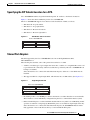
Specifying the SIP Subslot Location for a SPA
Cisco SCE8000-SIP subslots begin their numbering with “0” and have a horizontal orientation.
Figure 2-3 shows the subslot numbering for the Cisco SCE8000-SIP.
The Cisco SCE8000-SIP supports four subslots for the installation of SPAs, as follows:
•
SIP subslot 0—Top–left subslot
•
SIP subslot 1—Top–right subslot
•
SIP subslot 2—Bottom–left subslot
•
SIP subslot 3—Bottom–right subslot
Figure 2-3
SPA Module Subslot Location
Sub-slot 0
Sub-slot 1
Sub-slot 2
Sub-slot 3
270900
Front of SCE8000-SIP
Shared Port Adapters
The SPA supported by the Cisco SCE8000-SIP is the 1-Port 10-Gigabit Ethernet SPA,
SPA-1X10GE-L-V2
The following list describes some of the general characteristics of a SPA:
•
A SPA is a modular type of port adapter that inserts into a subslot of a compatible SIP carrier card
to provide network connectivity and increased interface port density. The Cisco SCE8000-SIP can
hold up to four SPAs.
Since the interfaces are connected in subscriber/network pairs, either two or four SPAs must be
installed.
•
The supported SPA is a single-height SPAs, which inserts into one SIP subslot. (See Figure 2-4.)
Figure 2-4
Single-Height SPA Size
Single-height SPA
Single-height SPA
Single-height SPA
Single-height SPA
242234
Front of the SCE8000-SIP
•
Each SPA provides a one 10GBE port, which is the interface to either subscriber or network traffic.
These interfaces can be individually configured using the Cisco command-line interface (CLI).
•
Either a blank filler plate or a functional SPA should reside in every subslot of an SIP during normal
operation to maintain cooling integrity. Blank filler plates are available in single-height form only.
Since the interfaces are connected in subscriber/network pairs, the SCE8000-SIP must be either
fully populated or have both the bottom bays covered with blank filler plates.
Cisco SCE8000 Installation and Configuration Guide, Rel 3.1.7
OL-16478-02
2-5
Chapter 2
Introduction to the Cisco SCE8000 Platform
Introduction to SIPs and SPAs
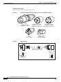
Modular Optics
The SPAs implement 10GBE small form-factor pluggable (XFP) optical transceivers to provide network
connectivity. An XFP module is a transceiver device that mounts into the front panel to provide network
connectivity.
Note
It is highly recommended only to use the XFP modules listed as supported in this document. Use of
unsupported or unqualified XFP modules may affect reliability or operation.
10GBE Small Form-factor Pluggable (XFP)
129499
Figure 2-5
The interface connector on the 1-Port 10-Gigabit Ethernet SPA is a fiber optic receiver that supports one
XFP.
The types of optics modules that have been qualified for use with the 1-Port 10-Gigabit Ethernet SPA on
the Cisco SCE8000 platform are as follows:
•
XFP-10GLR-OC192SR
•
XFP-10GER-OC192IR
•
XFP-10GZR-OC192LR
•
XFP-10G-MM-SR
XFP Connections
The qualified XFPs include an optical transmitter and receiver pair integrated with Clock and Data
Recovery (CDR) integrated circuits. The XFPs provide high-speed serial links at 10.3125 Gbps on single
mode fibers.
The transmit side recovers and retimes the 10 Gbps serial data and passes it to a laser driver. The laser
driver biases and modulates a laser, enabling data transmission over fiber through an LC connector. The
receive side recovers and retimes the 10 Gbps optical data stream from a photo detector trans impedance
amplifier and passes it to an output driver.
See the label on the XFP for technology type and model.
XFP dimensions are:
•
Height 12.5 mm
•
Width 18.35 mm
•
Length 71.1mm
Cisco SCE8000 Installation and Configuration Guide, Rel 3.1.7
2-6
OL-16478-02
Chapter 2
Introduction to the Cisco SCE8000 Platform
Introduction to SIPs and SPAs
The XFP operating temperature range is 0°C to 70°C.
Table 2-4
XFP Port Cabling Specifications
XFP
Wavelength
Fiber Type
XFP-10GLR-OC192SR
1310 nm
SMF
XFP-10GER-OC192IR
1550 nm
SMF
XFP-10GZR-OC192LR
1550 nm
SMF
XFP-10G-MM-SR
850 nm
MMF
The SCE8000-SIP
Table 2-5
SCE8000-SIP LED
LEDs
Description
Status
•
Green —Operational
•
Flashing Amber - Electrical bypass in operation
•
Red - Not initialized or failed
•
Unlit —No power
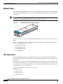
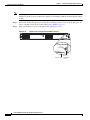
The 1-Port 10GBE SPA Interface Module
The SCE8000-SIP is installed in slot #3 of the Cisco SCE8000 chassis. It hosts up to four single-width,
single-height 1-Port 10GBE SPA interface modules, but in the Cisco SCE8000, it must be configured
with either two 1-Port 10GBE SPAs (in the top two subslots) or four 1-Port 10GBE SPAs, to provide
interfaces for either one or two complete traffic links.
1-Port 10GBE SPA Interface Module
122151
K
/LIN
ST
AT
U
S
Figure 2-6
IVE
T
AC
SPA-1X10GE-L-V2
1
2
Cisco SCE8000 Installation and Configuration Guide, Rel 3.1.7
OL-16478-02
2-7
Chapter 2
Introduction to the Cisco SCE8000 Platform
The Cisco SCE8000 Optical Bypass
Table 2-6
SPA Ports
Port
Quantity
Description
Connect This Port To…
10 GBE Line
port
1 on each SPA
Any one of the following:
Any one of the following:
•
XFP
XFP-10GLR-OC192SR
(10km)
•
XFP-10GER-OC192IR
(40km)
•
XFP-10GZR-OC192LR
(80km)
•
XFP-10G-MM-SR
(200m)
CLI designation: interface
TenGigabitEthernet 3/0/0,
3/1/0/, 3/2/0, 3/3/0.
Table 2-7
LEDs
Active/Link (1)
Status (2)
•
Subscriber side network
component
•
Network side network
component
•
Optical bypass 10GBE line
port
•
10GBE line port of a
cascaded SCE8000 platform
•
EtherChannel port of a
Cisco 7600 Series router
(MGSCP topology)
Refer to Connecting the Line
Ports to the Network,
page 6-1for further information.
SPA LEDs
Description
•
Green —Port is enabled by software and the link is up.
•
Amber — Port is enabled by software and the link is down.
•
Unlit — Port is not enabled by software.
The Status LED indicates the operational status of the SPA module, as
follows:
•
Green — SPA is ready and operational.
•
Amber — SPA power is on and good, and SPA is being configured.
•
Off — SPA power is off.
The Cisco SCE8000 Optical Bypass
•
Optical Bypass Functionality, page 2-9
•
Optical Bypass Module (OPB-SCE8K), page 2-9
The Cisco SCE8000 platform optical bypass module preserves the service provider 10GBE links under
all circumstances. At power failure the bypass is automatically activated. It can also be activated by the
Cisco SCE8000 software.
The Cisco SCE8000 platform already includes an internal electrical bypass, but it is strongly
recommended to use the optical bypass module for addressing the following scenarios:
•
During platform reboot (SW reload)—If the external bypass module is not used, there is a 5-second
period (at most) during which the link is forced down (cutoff functionality).
Cisco SCE8000 Installation and Configuration Guide, Rel 3.1.7
2-8
OL-16478-02
Chapter 2
Introduction to the Cisco SCE8000 Platform
The Cisco SCE8000 Optical Bypass
•
During a power failure —The Cisco SCE8000 has two power supplies. A power failure occurs only
when both of them fail.
In a case where the Cisco SCE8000 platform must be replaced, it is possible to remove the bypass
modules from the SCE8000 chassis without disconnecting them from the network and then reinstall them
in the new SCE platform, so that traffic links are preserved even in a case of complete failure and
replacement of the Cisco SCE8000 platform. (See Replacing the Optical Bypass Module without
Disrupting Traffic on the Link, page 9-26.)
Optical Bypass Functionality
The optical bypass module is connected bump-in-the-wire in the 10-GBE link. It is then connected to the
Cisco SCE8000 platform with two types of connections:
•
10GBE optical connections for data link traffic — 10 GBE connections from the optical bypass
module to one pair of the 10GBE SPA ports.
•
Control connection — Connection to the RJ-11 External Bypass connector on the SCE8000-SCM,
so the optical bypass is activated if the Cisco SCE8000 platform fails.
Optical Bypass Module Connectivity
The optical bypass module functions as follows:
•
Under normal conditions, the bypass module directs traffic to flow via the Cisco SCE8000.
•
Under failure conditions, the optical bypass shortcuts the interfaces that are connected to the traffic
link, and all traffic flows through the optical bypass module, bypassing the SCE platform.
Figure 2-7
Optical Bypass Module Connectivity
Default bypass state (no power)
Non-default bypass state
OPB
3/0/0
3/1/0
OPB
242125
3/2/0
3/3/0
SCE8000
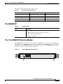
Optical Bypass Module (OPB-SCE8K)
There are two types of optical bypass modules to support different optic types:
•
OPB-SCE8K-SM supports Single-Mode optics and should be used with SCE8000 equipped with
Single-Mode optics.
Cisco SCE8000 Installation and Configuration Guide, Rel 3.1.7
OL-16478-02
2-9
Chapter 2
Introduction to the Cisco SCE8000 Platform
The Cisco SCE8000 Optical Bypass
•
OPB-SCE8K-MM supports Multi-Mode optics and should be used with SCE8000 equipped with
Multi-Mode optics.
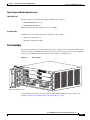
The optical bypass module is installed either internally, in slot #4 of the Cisco SCE8000 chassis or in an
external mounting panel in the rack.
Up to two optical bypass modules can be mounted internally, supporting inline insertion into two links.
Up to four optical bypass modules can be mounted using an external mount panel
(OPB-SCE8K-EXT-PNL). A single panel can serve two SCE8000 platforms, each cutting two links or
up to four SCE8000 platforms, each cutting a single link.
Figure 2-8
Optical Bypass Module
TX
TX
RX
TX
RX
A
A
B
A
C
TX
RX
C
D
B
D
CNTRL
RX
B
C
STATUS
D
OPB—SCE8K—MM
242235
OPTICAL BYPASS2
Table 2-8
Optical Bypass Module Ports
Port
Quantity
Description
10 GBE Line
port
4
10GBE ports A through D
CTRL
1
RJ-11 port
Table 2-9
Connect This Port To…
SPA interfaces on the Cisco
Duplex LC, panel mount adaptor SCE8000.
for LC/UPC connectors
Refer to Cabling the 10GBE
Line Interface Ports: Using the
External Optical Bypass
Module, page 6-11 for further
information.
RJ-11 Optical Bypass port on the
SCE8000-SCM-E
Optical Bypass Module LEDs
LEDs
Description
Status
The Status LED indicates the operational status of the optical bypass
module, as follows:
•
Green — Bypass module has been de-activated (traffic flows through the
Cisco SCE8000 platform)
•
Off — Bypass module is active (traffic does not flow through the Cisco
SCE8000 platform)
Cisco SCE8000 Installation and Configuration Guide, Rel 3.1.7
2-10
OL-16478-02
Chapter 2
Introduction to the Cisco SCE8000 Platform
The Cisco SCE8000 Optical Bypass
Optical Bypass Module Specifications
Fiber Cable Type
The fiber cable type within the Optical Bypass Module area as follows:
•
OPB-SCE8K-MM: 50 um core.
•
OPB-SCE8K-SM: SMF-28
Maximum optical path (fiber length of two ports) is 600m.
Switching Time
Switching time is measured from trigger to stable 90% optical output.
•
Typical switching time: 3 ms
•
Maximal switching time: 10ms
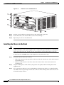
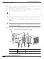
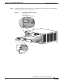
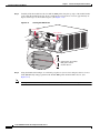
Fan Assembly
The system fan assembly, located in the chassis, provides cooling air for the installed modules. Sensors
on the fan assembly and within the system monitor the internal air temperatures. If the air temperature
exceeds a preset threshold, the environmental monitor displays warning messages.
Figure 2-9
Fan Assembly
SCE8000-SC
M-E
OPTICAL
BYPASS
FAN
STATUS
CONSOLE
PORT 1
10 100
1000
STATUS
OPTICAL
BYPASS
LINK
ACTIVE
SCE8000-SC
M-E
OPTICAL
BYPASS
AUX
CONSOLE
PORT 1
10 100
1000
SCE8000
EXTENDED
SERVICE
CONTROL
MODULE
PORT 2
10 100
1000
OPTICAL
BYPASS
LINK
ACTIVE
MASTER
SYSTEM
POWER
STATUS
OPTICAL
BYPASS
LINK
ACTIVE
SCE8000-SIP
OPTICAL
BYPASS
ACT
IVE/LIN
K
AUX
SCE8000
EXTENDED
SERVICE
CONTROL
MODULE
PORT 2
10 100
1000
LINK
ACTIVE
MASTER
SYSTEM
POWER
US
AT
ST
K
SPA-1X
10GE-L
-V2
ACT
AT
ST
SPA-1X
10GE-L
K
IVE/LIN
US
-V2
ACT
US
AT
ST
K
IVE/LIN
SPA-1X
10GE-L
-V2
270893
IVE/LIN
ACT
TX
TX
TX
RX
TX
RX
RX
RX
OPTICAL
BYPASS
1
A
B
A
C
C
D
B
D
CTRL
US
AT
ST
SPA-1X
10GE-L
-V2
STATUS
OPB-SC
E8K-MM
TX
TX
TX
RX
TX
RX
RX
RX
OPTICAL
BYPASS
2
A
B
A
C
C
D
B
D
CTRL
STATUS
OPB-SCE
8K-MM
Captive installation screws
If an individual fan within the assembly fails, the FAN STATUS LED turns red. To replace a fan
assembly, see Removing and Replacing the Fan Assembly, page 9-10.
Cisco SCE8000 Installation and Configuration Guide, Rel 3.1.7
OL-16478-02
2-11
Chapter 2
Introduction to the Cisco SCE8000 Platform
The Cisco SCE8000 Optical Bypass
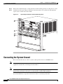
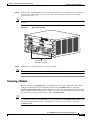
Power Supplies
The Cisco SCE8000 platform supports redundant AC- or DC-input power supplies. The following power
supplies are available for the Cisco SCE8000 platform:
•
2700 W DC input (PWR-2700-DC/4): uses an external terminal block on the back side of the chassis
for input power connection.
•
2700 W AC input (PWR-2700-AC/4): uses an external power cord directly connected to the AC
power supply.
Figure 2-10
PWR-2700-AC/4
PWR-AC
100-240
V-16A
50/60Hz
INPUT
OK
FAN OU
TPUT
OK
FAIL
Captive installation
screws
126565
ALL FA
ST
PRIOR ENERS MU
ST
TO OP
ERATING BE FULLY
ENGA
THE PO
WER SU GED
PPLY
Captive installation
screws
Figure 2-11
PWR-2700-DC/4
PWR-2
700-DC
/4
-VE-1
-VE-1
INPUT
1 INPUT
2 FA
OK
N OUTP
48V-60V OK
UT
48V-60V OK
FAIL
=40A
=40A
-VE-2
-VE-2
ALL FA
ST
PRIOR ENERS MU
ST
TO OP
ERATING BE FULLY
ENGA
THE PO
WER SU GED
PPLY
132218
Captive installation
screws
Captive installation
screws
The AC-input and DC-input power supplies support redundancy. When power is removed from one
supply, the redundant power feature causes the second supply to produce full power.
Cisco SCE8000 Installation and Configuration Guide, Rel 3.1.7
2-12
OL-16478-02
Chapter 2
Introduction to the Cisco SCE8000 Platform
Checking the Shipping Container Contents
Power Supply Cooling
Power supplies have built-in fans and are completely self-cooling. Air enters from the right of the fan
and exits through the left.
Load Sharing
With two power supplies, each power supply concurrently provides approximately half of the required
power to the system. If one power supply fails, the second power supply immediately assumes full power
to maintain uninterrupted system operation. The second power supply enables load sharing and fault
tolerance automatically; no software configuration is required.
Checking the Shipping Container Contents
Use the Cisco SCE8000 Component List to check the contents of the Cisco SCE8000 platform shipping
container.
Tip
Do not discard the shipping container when you unpack the Cisco SCE8000. Flatten the shipping cartons
and store them with the pallet. You will need these containers if you need to move or ship the Cisco
SCE8000 in the future.
Cisco SCE8000 Installation and Configuration Guide, Rel 3.1.7
OL-16478-02
2-13
Chapter 2
Introduction to the Cisco SCE8000 Platform
Checking the Shipping Container Contents
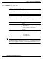
Cisco SCE8000 Component List
Table 2-10
Cisco SCE8000 Component List
Component
Description
Cisco SCE8000 platform
Cisco SCE8000 10GBE chassis configured with the
following components:
Cisco SCE8000-SCM-E
Cisco SCE8000 Service Control Module
Cisco SCE8000-SIP
Cisco SCE8000 SPA Jacket card Interface Processor
2 or 4 SPA Jacket cards
SPA Interface. See below the list of supported SPA models.
2 or 4 XFP OpticsXFP optic modules.
See below the list of supported XFP models
2 Cisco PWR-2700-AC/4 or
2 Cisco PWR-2700-DC/4
Cisco power supply units, AC or DC.
Hot swappable, redundant power supply, compatible with
Cisco 7604 router.
SCE8000-FAN
Redundant fans unit.
Accessories
The following accessories might arrive in separate shipping
containers:
Management cables
Power cables
Grounding kit 69-0815-01
Optical Bypass module kit
Note
•
Gigabit Ethernet cable for connecting to the
Management ports
•
RS-232 serial cables (DB-9 to RJ-45 and DB-25 to
RJ-45) for connecting to a local terminal
Two AC power supply cords, if ordered with AC-input power
supply units
•
Grounding lug
•
Two M4 hex-head screws with locking washers
•
Optical Bypass Module
•
Control Cable (2 m)
•
Control Cable (40 cm)
Cisco does not ship the entire Cisco SCE8000 documentation set automatically with each system. You
must specifically order the documentation as part of the sales order. If you ordered documentation and
did not receive it, we will ship the documents to you within 24 hours. To order documents, contact a
customer service representative.
Cisco SCE8000 Installation and Configuration Guide, Rel 3.1.7
2-14
OL-16478-02
Chapter 2
Introduction to the Cisco SCE8000 Platform
Cisco SCE8000 Installation Checklist
Cisco SCE8000 Installation Checklist
To assist you with your installation and to provide a historical record of what was done by whom,
photocopy the following Cisco SCE8000 Installation Checklist. Indicate when each procedure or
verification is completed. When the checklist is completed, place it in your site log along with the other
records for your new Cisco SCE8000 platform.
Table 2-11
Cisco SCE8000 Installation Checklist
Task
Verified By
Date
Date Cisco SCE8000 received
Cisco SCE8000 and all accessories unpacked
Safety recommendations and guidelines reviewed
Topology verified: number of Cisco SCE8000 platforms, number of
links, and whether inline or receive-only
Installation Checklist copied
Site log established and background information entered
Site power voltages verified
Site environmental specifications verified
Required passwords, IP addresses, device names, and so on, needed
for initial configuration available (refer to Initial Setup Parameters,
page 5-2)
Required tools available
Network connection equipment available
Cisco SCE8000 mounted in rack
System grounding established, if required
AC/DC power cables connected to AC/DC sources and Cisco
SCE8000 chassis
Optical bypass modules installed (optional)
Console port set for 9600 baud, 8 data bits, no parity, and 1 stop bit
(9600 8N1)
ASCII terminal attached to console port
Management port is operational
Network interface cables and devices connected
System power turned on
System boot complete (Status LED is on)
10 GBE line ports operational
Correct hardware configuration displayed after system banner
appears
Cisco SCE8000 Installation and Configuration Guide, Rel 3.1.7
OL-16478-02
2-15
Chapter 2
Introduction to the Cisco SCE8000 Platform
Cisco SCE8000 Installation Checklist
Cisco SCE8000 Installation and Configuration Guide, Rel 3.1.7
2-16
OL-16478-02
CH A P T E R
3
Cisco SCE8000 Topology and Topology-Related
Parameters
This chapter describes the possible deployment topologies of the Cisco SCE8000 and explains how to
configure the relevant parameters correctly for each topology.
•
The Cisco SCE8000 Platform, page 3-1
•
Topology Considerations, page 3-1
•
Physical Topologies, page 3-3
•
Link Continuity, page 3-9
•
Topology-Related Parameters, page 3-11
•
Asymmetric Routing Topology, page 3-13
The Cisco SCE8000 Platform
The Cisco SCE8000 is a solution for dual links with load sharing and asymmetrical routing and support
for fail-over between two SCE platforms.
The Cisco SCE8000 is built to support wire speed processing of full-duplex 10GBE streams. The Cisco
SCE8000 can, therefore, be deployed in a multi-link environment, in several different topologies.
•
Single Cisco SCE8000 topology — Provides the ability to process both directions of a bi-directional
flow, processing both the upstream and downstream paths of a flow, even if they traverse different
links.
•
Dual Cisco SCE8000 topology (cascade) — Cascaded Cisco SCE8000s provide high-availability
and fail-over solution and maintain the line and service in case of Cisco SCE8000 failure
•
Multi-Gigabit Service Control Platform (MGSCP) topology — For scalability, the Cisco SCE8000
platform supports the option to connect a multiple number of SCE platforms to a Cisco 7600 Series
router used to perform load-balancing between the platforms.
Topology Considerations
There are several issues that must be considered in order to arrive at the optimum configuration of the
topology-related parameters:
•
Functionality
Cisco SCE8000 Installation and Configuration Guide, Rel 3.1.7
OL-16478-02
3-1
Chapter 3
Cisco SCE8000 Topology and Topology-Related Parameters
Topology Considerations
— Will the system be used solely to monitor traffic flow, with report functionality only, or will it be
used for traffic flow control, with enforcement as well as report functionality?
– Monitoring and Control — The Cisco SCE8000 monitors and controls traffic flow. Decisions
are enforced by the Cisco SCE8000 depending on the results of the monitoring functions of the
Cisco SCE8000 and the configuration of the Service Control Application for Broadband or
Mobile solution.
In order to perform control functions, the Cisco SCE8000 must be physically installed as an inline
installation.
– Monitoring only — The Cisco SCE8000 monitors traffic flow, but cannot control it.
Either an inline installation or an optical splitter or port SPAN installation may be used for
monitoring only.
•
Size
A Cisco SCE8000 deployment can range from a single 10GBE link to multiple platforms in a
MGSCP topology.
A complete discussion on sizing the system is beyond the scope of this document. Information
regarding the number of Cisco SCE8000 platforms required is related to the design considerations
'per link' (topology and redundancy factors) rather than to overall sizing of the system.
•
Redundancy
Must the system be designed to guarantee uninterrupted Cisco SCE8000 functionality? If so, there
must be a backup Cisco SCE8000 platform (or a backup for each platform in an MGSCP topology)
to assume operation in case of failure of the primary device.
A backup SCE platform is connected in a cascade configuration with the primary SCE platform so
that, although all processing is performed only in the active Cisco SCE8000, the standby Cisco
SCE8000 is constantly updated with all the necessary information so that it can instantly take over
processing the traffic on the data links should the active Cisco SCE8000 fail.
Note that an MGSCP topology with multiple Cisco SCE8000 platforms provides more sophisticated
redundancy options, but the basic decision on each link is the same: does it require a standby SCE
platform or not?
•
Link continuity
How should the Cisco SCE8000 respond to platform failure with regard to link continuity? Should
traffic flow continue even though the unit is not operating, or be halted until the platform is
repaired/replaced?
If link continuity is a high priority, an external optical bypass module can be installed on the link.
(See Link Continuity, page 3-9 and The Cisco SCE8000 Optical Bypass, page 2-8.)
Note
In cascade configuration, installation of an external optical bypass module is required.
These issues determine two important aspects of system deployment and configuration:
•
Physical topology of the system — The actual physical placement and connection of the Cisco
SCE8000 platform or platforms in the system.
•
Topology-related configuration parameters — The correct values for each parameter must be
ascertained before configuring the system to make sure that the system will function in the desired
manner.
Cisco SCE8000 Installation and Configuration Guide, Rel 3.1.7
3-2
OL-16478-02
Chapter 3
Cisco SCE8000 Topology and Topology-Related Parameters
Physical Topologies
Physical Topologies
Following are descriptions of a number of physical topologies that the Cisco SCE8000 supports.
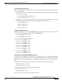
•
SCE8000 Interface Numbering, page 3-3
•
Single Cisco SCE8000 Topologies, page 3-3
•
Dual Cisco SCE8000 Topology (Cascade), page 3-6
•
Multi-Gigabit Service Control Platform (MGSCP) Topology, page 3-7
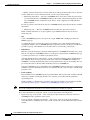
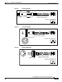
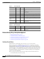
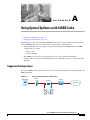
SCE8000 Interface Numbering
The following diagram shows the numbering of the SCE8000 interfaces as indicated in the topology
diagrams in this chapter. The interface numbering is explained as follows:
•
The first digit is the slot number (always 3).
•
The second digit is the number of the sub-slot or SPA module (0-3).
•
The third digit is the number of the interface on the designated SPA module (always 0).
•
Interfaces 3/0/0 and 3/2/0 are on the two left-hand SPA modules and are the Subscriber side
interfaces.
•
Interfaces 3/1/0 and 3/3/0 are on the two right-hand SPA modules and are the Network side
interfaces.
SCE8000 Interface Numbering
Subscriber
3/0/0
3/1/0
Network
Subscriber
3/2/0
3/3/0
Network
270591
Figure 3-1
Single Cisco SCE8000 Topologies
A single Cisco SCE8000 supports both single 10GBE link and dual 10GBE link topologies.
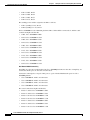
•
Single Link: Inline Topology, page 3-4
•
Dual link: Inline Installation, page 3-4
•
Single Link: Receive-only Topology, page 3-5
•
Dual Link: Receive-Only Topology, page 3-5
Cisco SCE8000 Installation and Configuration Guide, Rel 3.1.7
OL-16478-02
3-3
Chapter 3
Cisco SCE8000 Topology and Topology-Related Parameters
Physical Topologies
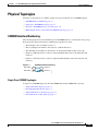
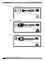
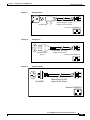
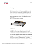
Single Link: Inline Topology
Typically, the Cisco SCE8000 is connected in a full duplex 10GBE link between two devices (Router,
BRAS, etc.). When the Cisco SCE8000 is installed as an inline installation, it physically resides on the
data link between the subscribers and the network.
Figure 3-2
Single Link: Inline Topology
3/0/0
3/1/0
3/2/0
3/3/0
Network
270588
Subscriber
When configuring the Cisco SCE8000, an inline installation is referred to as “inline” connection mode.
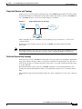
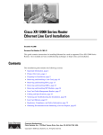
Dual link: Inline Installation
In this topology, one Cisco SCE8000 is connected inline in two full duplex, 10GBE links.
In case the two links are load-shared, asymmetrical routing might occur, and some of the flows may be
split, that is, the upstream packets of the flow go on one link, and the downstream packets go on the other
link.
When installed in this topology, the Cisco SCE8000 completely overcomes this phenomenon, and
provides its normal functionality as if asymmetrical routing were not occurring in the two links.
Figure 3-3
Dual link: Inline Installation
Subscriber 1
3/0/0
3/1/0
3/2/0
3/3/0
Network 1
Subscriber 2
270589
Network 2
This topology supports both monitoring and control functionality, and is referred to as “inline”
connection mode.
Cisco SCE8000 Installation and Configuration Guide, Rel 3.1.7
3-4
OL-16478-02
Chapter 3
Cisco SCE8000 Topology and Topology-Related Parameters
Physical Topologies
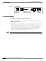
Single Link: Receive-only Topology
In this topology, an optical splitter resides physically on the 10GBE link between the subscribers and the
network. The traffic passes through the optical splitter, which splits traffic to the Cisco SCE8000. The
Cisco SCE8000, therefore, only receives traffic and does not transmit.
Figure 3-4
Single Link: Receive-only Topology
Splitter
Network
3/0/0
3/1/0
3/2/0
3/3/0
270586
Subscriber
When configuring the Cisco SCE8000, an optical splitter topology is referred to as “receive-only”
connection mode.
Note that in an optical splitter topology, the Cisco SCE8000 only enables traffic monitoring
functionality.
Note
When implementing receive-only topologies with a switch, the switch must support SPAN functionality
that includes separation between ingress and egress traffic and multiple SPAN-ports destinations.
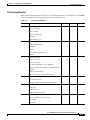
Dual Link: Receive-Only Topology
In this topology, one Cisco SCE8000 is connected in receive-only mode to two full duplex, 10 Gig links
using optical splitters. If the two links are load-shared, asymmetrical routing might occur, and some of
the flows may be split, i.e. the upstream packets of the flow go on one link, and the downstream packets
go on the other link.
When installed in this topology, the Cisco SCE8000 completely overcomes this phenomenon, and
provides its normal monitoring functionality as if asymmetrical routing were not occurring in the two
links.
This installation supports monitoring functionality only, and is configured as “receive-only” connection
mode.
Cisco SCE8000 Installation and Configuration Guide, Rel 3.1.7
OL-16478-02
3-5
Chapter 3
Cisco SCE8000 Topology and Topology-Related Parameters
Physical Topologies
Figure 3-5
Dual Link: Receive-Only Topology
Subscriber 1
Splitter
3/0/0
3/1/0
3/2/0
3/3/0
270587
Network 1
Network 2
Splitter
Subscriber 2
Note
When implementing receive-only topologies with a switch, the switch must support SPAN functionality
that includes separation between ingress and egress traffic and multiple SPAN-ports destinations.
Dual Cisco SCE8000 Topology (Cascade)
In this topology, two cascaded Cisco SCE8000s are used. This allows a fail-over solution, where in case
of a failure of one Cisco SCE8000 the functionality that the Cisco SCE8000 provides is preserved by the
redundant platform.
This topology allows both control and monitoring functionality where redundancy is required and
“inline” connection is used. The two Cisco SCE8000s are cascaded, so the primary Cisco SCE8000
processes the traffic of the two links, while the secondary Cisco SCE8000 only bypasses the traffic of
its links to the primary Cisco SCE8000 for processing, and then bypasses the processed traffic back to
the link. The two Cisco SCE8000s also exchange keep-alive messages and subscriber state information.
In case the primary Cisco SCE8000 fails, the two Cisco SCE8000s switch their roles, and this way
fail-over is provided.
Figure 3-6
Two Cascaded Cisco SCE8000 Platforms
Subscriber
3/0/0
3/1/0
3/2/0
3/3/0
3/2/0
3/3/0
3/0/0
3/1/0
Network
Subscriber
270590
Network
This fail-over solution preserves the Cisco SCE8000 functionality and the network link:
Cisco SCE8000 Installation and Configuration Guide, Rel 3.1.7
3-6
OL-16478-02
Chapter 3
Cisco SCE8000 Topology and Topology-Related Parameters
Physical Topologies
•
The two Cisco SCE8000s are simultaneously aware of the subscriber contexts, and subscriber states
are constantly exchanged between them, such that if the primary Cisco SCE8000 fails, the secondary
can take over with minimum state loss.
•
When one Cisco SCE8000 fails (depending on the type of failure) its link traffic is still bypassed to
the functioning Cisco SCE8000 and processed there, so the traffic processing continues for both the
links.
•
The bypass of the traffic through the failed Cisco SCE8000 is configurable, and the user may choose
to always cutoff the line that goes through the failed Cisco SCE8000. In this case network
redundancy protocols like HSRP are responsible for identifying the line cutoff and switching all the
traffic to go through the functioning Cisco SCE8000.
•
In addition, it is possible to configure the Cisco SCE8000 to use the external optical bypass device
so that in the event of any failure of the Cisco SCE8000, it will be used to provide link continuity.
This ensures 100% link continuity at the expense of providing asymmetric routing functionality.
Multi-Gigabit Service Control Platform (MGSCP) Topology
In this topology, multiple Cisco SCE8000 platforms are connected to a Cisco 7600 Series router, which
acts as a dispatcher between the platforms. The router contains two EtherChannels (ECs), one for the
subscriber side and one for the network side, that perform load balancing for the SCE platform traffic.
Traffic enters the first router, is distributed between the SCE platforms by the subscriber-side EC and
then returns to the router so it can be forwarded to its original destination.
Figure 3-7
Basic MGSCP Topology
Cisco 7600
40Gig
Internet
270877
Subscribers
4+1
SCE8000s
There are a number of variables to be considered in the MGSCP topology. Two of the main factors to be
considered include:
•
Type of SCE Platform Redundancy, page 3-8
•
Redundant Cisco 7600 Series Router, page 3-8
Cisco SCE8000 Installation and Configuration Guide, Rel 3.1.7
OL-16478-02
3-7
Chapter 3
Cisco SCE8000 Topology and Topology-Related Parameters
Physical Topologies
Type of SCE Platform Redundancy
•
All Active
All ports in the EC and all SCE platforms are active. If there is a failure in one of the SCE platforms,
the links on the related ports in the EC will be down and the EC will automatically exclude it from
the load distribution. The load will then be distributed between the remaining active SCE platforms.
Since the Cisco SCE8000 supports two links, this configuration requires one SCE platform per two
links (two EC ports).
•
N+1
'N' SCE platforms are active and one platform is on standby. The EC ports connected to the standby
SCE platform must be configured as standby ports. In the case of failure of one of the SCE platforms,
the EC ports connected to the failing SCE platform are shut and the standby EC ports, connected to
the standby SCE platform, will be activated.
Since the Cisco SCE8000 supports two links, this configuration requires one SCE platform per two
links (two EC ports), plus one extra SCE platform for standby.
Note that the standby SCE platform must be connected to the two highest-numbered ports, since EC
behavior automatically designates these as the standby ports.
Redundant Cisco 7600 Series Router
Two Cisco 7600 Series routers can be used to provide network redundancy.
In this topology, one link on each Cisco SCE8000 platform is connected to each router. Therefore, one
SCE platform is required for each link.
Figure 3-8
MGSCP with Redundant Router
Cisco 7600
40Gig
Internet
4+1
SCE8000s
270883
Subscribers
40Gig
Cisco 7600
Cisco SCE8000 Installation and Configuration Guide, Rel 3.1.7
3-8
OL-16478-02
Chapter 3
Cisco SCE8000 Topology and Topology-Related Parameters
Link Continuity
Link Continuity
The internal bypass mechanism of the Cisco SCE8000 allows traffic to continue to flow, if desired, even
if the device itself is not fully functioning. In addition, the Cisco SCE8000 is designed with the ability
to control up to two external optical bypass devices (one per link). This is needed because the internal
bypass mechanism cannot maintain traffic flow in all cases.
Note that when the Cisco SCE8000 is connected to the network through an optical splitter, a failure of
the Cisco SCE8000 does not affect the traffic flow, as the traffic continues to flow through the optical
splitter.
•
Internal Bypass Mechanism, page 3-9
•
External Optical Bypass, page 3-9
Internal Bypass Mechanism
The Cisco SCE8000 includes a SPA Interface Processor module with a bypass mechanism that is enabled
upon Cisco SCE8000 failure.
The SPA Interface Processor card supports the following three modes:
•
Bypass — The bypass mechanism preserves the network link, but traffic is not processed for
monitoring or for control.
•
Forwarding — This is the normal operational mode, in which the Cisco SCE8000 processes the
traffic for monitoring and control purposes.
•
Cutoff — There is no forwarding of traffic, and the physical link is forced down (cutoff
functionality at layer 1).
The SPA Interface Processor card cannot preserve the link in the following circumstances:
•
During platform reboot (SW reload), there is a 5-second period (at most) during which the link is
forced down (cutoff functionality).
•
During a power failure (The Cisco SCE8000 has two power supplies. A power failure occurs only
when both of them fail).
•
Under certain types of failure within the SIP module, the SPA cards, or the XFP optic modules.
External Optical Bypass
In installations in which the limitations of the internal bypass are not acceptable, an external optical
bypass device can be used to provide dependable link continuity. The external optical bypass device can
be installed either inside the Cisco SCE8000 chassis or be rack-mounted externally. The external optical
bypass device can also be controlled manually by specific CLI commands.
Under normal operating conditions, traffic flows through the link as usual, with the exception that the
optical bypass module sits on the link.
Cisco SCE8000 Installation and Configuration Guide, Rel 3.1.7
OL-16478-02
3-9
Chapter 3
Cisco SCE8000 Topology and Topology-Related Parameters
Link Continuity
Figure 3-9
Optical Bypass Under Normal Operating Conditions
Subscriber 1
OPB
Network 1
3/0/0
3/1/0
3/2/0
3/3/0
Network 2
OPB
270904
Subscriber 2
If the SCE8000 platform fails, traffic flows through the optical bypass module, bypassing the SCE8000,
so that traffic on the link is maintained
Figure 3-10
Optical Bypass Under Failure Conditions
Subscriber 1
OPB
Network 1
3/0/0
3/1/0
3/2/0
3/3/0
Network 2
Note
270903
Subscriber 2
OPB
In cascade configuration, installation of the optical bypass module is required
This optical bypass module can be added to link without altering the basic characteristics of the
topology. (The installation procedure and the actual connections are somewhat different when the
optical bypass module is used, see Optical Bypass Module Connectivity, page 6-8.)
For more information regarding the external bypass module, refer to The Cisco SCE8000 Optical
Bypass, page 2-8.
Cisco SCE8000 Installation and Configuration Guide, Rel 3.1.7
3-10
OL-16478-02
Chapter 3
Cisco SCE8000 Topology and Topology-Related Parameters
Topology-Related Parameters
Topology-Related Parameters
Refer to the following sections to determine the correct values for all topology-related parameters before
beginning to run the initial setup of the Cisco SCE8000.
•
Connection Mode Parameter, page 3-11
•
Physically Connected Links Parameter, page 3-12
•
Priority, page 3-12
•
On-Failure Mode Parameter, page 3-12
There are four topology-related parameters:
•
Connection mode — Can be any one of the following, depending on the physical installation of the
Cisco SCE8000 (Refer to Connection Mode Parameter, page 3-11):
– Inline — single Cisco SCE8000 inline
– Receive-only — single Cisco SCE8000 receive-only
– Inline-cascade — two inline Cisco SCE8000 platforms cascaded
– Receive-only-cascade — two receive-only Cisco SCE8000 platforms cascaded
•
Physically-connected-links — In cascaded configurations, this parameter defines the number of the
link connected to the Cisco SCE8000 platform being configured. (Refer to Physically Connected
Links Parameter, page 3-12.)
It is applicable only in a cascade topology.
•
Priority — This parameter defines which is the primary Cisco SCE8000 (Refer to Priority,
page 3-12.)
It is applicable only in a cascade topology
•
On-failure — This parameter determines whether the system cuts the traffic or bypasses it when the
Cisco SCE8000 either has failed or is booting. Traffic bypass can be achieved either through the
external optical bypass device or through the internal bypass mechanism of the SPA interface
processor. It is not applicable to receive-only topologies. (Refer to On-Failure Mode Parameter,
page 3-12.)
These parameters are configured via the connection-mode command.
Connection Mode Parameter
The connection mode parameter refers directly to the physical topology in which the Cisco SCE8000 is
installed. The connection mode depends on two factors:
•
Inline/Receive-only:
– Inline — The Cisco SCE8000 resides on the data link between the subscriber side and the
network side, thus both receiving and transmitting packets.
– Receive-only — The Cisco SCE8000 does not reside physically on the data link. Data is
forwarded to the Cisco SCE8000 via an external optical splitter. The Cisco SCE8000 itself
receives only and does not transmit.
•
Cascade — Indicates a two Cisco SCE8000 topology where the two Cisco SCE8000 platforms are
connected via the cascade ports.
Cisco SCE8000 Installation and Configuration Guide, Rel 3.1.7
OL-16478-02
3-11
Chapter 3
Cisco SCE8000 Topology and Topology-Related Parameters
Topology-Related Parameters
The connection mode parameter is determined by the physical deployment of the Cisco SCE8000, as
follows:
•
Single Cisco SCE8000 inline installation = Inline connection mode.
•
Single Cisco SCE8000 optical splitter installation = Receive-only connection mode.
•
Two-platform cascaded Cisco SCE8000 inline installation = Inline-cascade connection mode.
•
Two-platform cascaded Cisco SCE8000 optical splitter installation = Receive-only-cascade
connection mode
Physically Connected Links Parameter
A cascade topology supports two traffic links. This parameter defines which link is connected to which
Cisco SCE8000 platform. The links are designated as follows:
•
Link 0
•
Link 1
Priority
In a cascade topology, the user must define the priority of each Cisco SCE8000.
•
Primary — The Primary Cisco SCE8000 is active by default
•
Secondary — The Secondary Cisco SCE8000 is the default standby.
Note that these defaults apply only when both devices are started together. However, if the primary
Cisco SCE8000 fails and then recovers, it will not revert to active status, but remains in standby status,
while the secondary device remains active
On-Failure Mode Parameter
The on-failure mode parameter configures the action taken by a failed box when a failure is detected.
As described in the section Internal Bypass Mechanism, page 3-9, the SPA Interface Processor card
supports three different modes. The Bypass and Cutoff modes are possible when the Cisco SCE8000 is
not operational due to platform failure or boot. The Forwarding mode enables control of traffic flow
and is not compatible with the non-operational status.
The following on-failure modes are possible:
•
Bypass — The SPA interface card forwards traffic between the two ports of each link with no
intervention of the control application running in the Cisco SCE8000 platform. This is also known
as 'electrical bypass'.
In a cascade setup, this allows the traffic of the link connected to the failed box to be passed to the
active box for processing.
•
Cutoff — There is no forwarding of traffic. The link is forced down, resulting in traffic cutoff at
Layer1.
•
External-bypass – The external optical bypass device is used to bypass traffic, maintaining link
continuity at all times.
Cisco SCE8000 Installation and Configuration Guide, Rel 3.1.7
3-12
OL-16478-02
Chapter 3
Cisco SCE8000 Topology and Topology-Related Parameters
Asymmetric Routing Topology
In a single Cisco SCE8000 topology, the value of this parameter is determined by whether or not the link
can be completely cut when the Cisco SCE8000 fails, or whether traffic flow should continue across the
link in spite of platform failure. In the latter case, the External-bypass mode is the recommended
setting, and is therefore the default value for the on-failure mode parameter.
In a dual cascaded Cisco SCE8000 topology, the default on-failure mode is Bypass, since it preserves
full traffic processing functionality on both links in most single box failures (as long as the SPA interface
card is functioning properly).
•
Cutoff mode is suggested for the following:
– Non-redundant inline topology if value-added services (such as security) are crucial and are
more important than maintaining connectivity.
•
Bypass mode is suggested for the following:
– Non-redundant inline topology if connectivity is of high importance.
– In redundant inline setups, if cutoff or traffic loss on a single link for a period of up to ten
minutes (during a rare event of a SPA interface card failure) can be tolerated.
•
External-bypass mode is suggested for the following:
– Non-redundant inline topology if connectivity is crucial.
– Redundant inline setups, if connectivity is crucial. Note that when this mode is used, the link
connected to the failed box is not serviced, and the other link operates with asymmetric routing
functionality.
Asymmetric Routing Topology
In some Service Control deployments, asymmetrical routing occurs between potential service control
insertion points. Asymmetrical routing can cause a situation in which the two directions of a
bi-directional flow pass through different SCE platforms, resulting in each SCE platform seeing only
one direction of the flow (either the inbound traffic or the outbound traffic).
This problem is typically solved by connecting the two SCE platforms in cascade mode (or through an
MGSCP cluster), thereby making sure that both directions of a flow run through the same SCE platform.
However, this is sometimes not feasible, due to the fact that the SCE platforms sharing the split flow are
geographically remote (especially common upon peering insertion). In this type of scenario, the
asymmetric routing solution enables the SCE platform to handle such traffic, allowing SCA BB to
classify traffic based on a single direction and to apply basic reporting and global control features to
uni-directional traffic.
Asymmetric Routing and Other Service Control Capabilities
Asymmetric routing can be combined with most other Service Control capabilities, however there are
some exceptions.
Service Control capabilities that cannot be used in an asymmetric routing topology include the
following:
•
Subscriber redirect
•
Subscriber notification
•
Any kind of subscriber integration. (Use subscriber-less mode or anonymous subscriber mode
instead)
Cisco SCE8000 Installation and Configuration Guide, Rel 3.1.7
OL-16478-02
3-13
Chapter 3
Cisco SCE8000 Topology and Topology-Related Parameters
Asymmetric Routing Topology
Cisco SCE8000 Installation and Configuration Guide, Rel 3.1.7
3-14
OL-16478-02
CH A P T E R
4
Installing the Cisco SCE8000 Chassis
This chapter describes how to install a Cisco SCE8000 chassis.
Warning
Before you install, operate, or service the system, read the Regulatory Compliance and Safety
Information for the Cisco SCE8000 Platform. This guide contains important safety information you
should know before working with the system.
Warning
Only trained and qualified personnel should be allowed to install, replace, or service this equipment.
Warning
Before working on a chassis or working near power supplies, unplug the power cord on AC units;
disconnect the power at the circuit breaker on DC units.
Warning
The plug-socket combination must be accessible at all times because it serves as the main
disconnecting device.
Warning
This unit is intended for installation in restricted access areas. A restricted access area can be
accessed only through the use of a special tool, lock and key, or other means of security.
Warning
There is the danger of explosion if the battery is replaced incorrectly. The battery is not a
user-serviceable part.
Warning
Class 1 laser product.
Warning
Because invisible laser radiation may be emitted from the aperture of the port when no cable is
connected, avoid exposure to laser radiation and do not stare into open apertures.
Cisco SCE8000 Installation and Configuration Guide, Rel 3.1.7
OL-16478-02
4-1
Chapter 4
Installing the Cisco SCE8000 Chassis
Preparing for Installation
Warning
Blank faceplates and cover panels serve three important functions: they prevent exposure to
hazardous voltages and currents inside the chassis; they contain electromagnetic interference (EMI)
that might disrupt other equipment; and they direct the flow of cooling air through the chassis. Do not
operate the system unless all cards, faceplates, front covers, and rear covers are in place.
•
Preparing for Installation, page 4-2
•
Installing the Cisco SCE8000 Chassis in the Rack, page 4-12
•
Connecting the System Ground, page 4-16
•
Installing the Power Supplies in the Cisco SCE8000 Chassis, page 4-18
Preparing for Installation
•
Safety, page 4-2
•
Site Requirements, page 4-2
•
Power Connection Guidelines, page 4-4
Safety
Warning
This equipment must be grounded. Never defeat the ground conductor or operate the equipment in the
absence of a suitably installed ground conductor. Contact the appropriate electrical inspection
authority or an electrician if you are uncertain that suitable grounding is available.
Warning
Read the installation instructions before connecting the system to the power source.
Warning
This product requires short-circuit (overcurrent) protection, to be provided as part of the building
installation. Install only in accordance with national and local wiring regulations.
Site Requirements
This section provides site power requirements for the Cisco SCE8000 chassis. You should verify the site
power prior to installation.
•
Preventing Electrostatic Discharge Damage, page 4-3
•
Environmental Requirements, page 4-3
•
Power Requirements, page 4-3
Cisco SCE8000 Installation and Configuration Guide, Rel 3.1.7
4-2
OL-16478-02
Chapter 4
Installing the Cisco SCE8000 Chassis
Preparing for Installation
Preventing Electrostatic Discharge Damage
Electrostatic discharge (ESD) damage, which can occur when electronic cards or components are
improperly handled, results in complete or intermittent failures. Port adapters and blades consist of
printed circuit boards that are fixed in metal carriers. Electromagnetic interference (EMI) shielding and
connectors are integral components of the carrier. Although the metal carrier helps to protect the board
from ESD, use a preventive antistatic strap during handling.
Following are guidelines for preventing ESD damage:
Caution
•
Always use an ESD wrist or ankle strap and ensure that it makes good skin contact.
•
Connect the equipment end of the strap to an unfinished chassis surface.
•
When installing a component, use any available ejector levers or captive installation screws to
properly seat the bus connectors in the backplane or midplane. These devices prevent accidental
removal, provide proper grounding for the system, and help to ensure that bus connectors are
properly seated.
•
When removing a component, use any available ejector levers or captive installation screws to
release the bus connectors from the backplane or midplane.
•
Handle carriers by available handles or edges only; avoid touching the printed circuit boards or
connectors.
•
Place a removed component board-side-up on an antistatic surface or in a static shielding container.
If you plan to return the component to the factory, immediately place it in a static shielding
container.
•
Avoid contact between the printed circuit boards and clothing. The wrist strap only protects
components from ESD voltages on the body; ESD voltages on clothing can still cause damage.
•
Never attempt to remove the printed circuit board from the metal carrier.
For safety, periodically check the resistance value of the antistatic strap. The measurement should be
between 1 and 10 megohm (Mohm).
Environmental Requirements
Ensure adequate spacing between racks using the information in the following table. Keep all of the
vents clear of obstructions, including dust and foreign conductive material, and away from the exhaust
ports of other equipment.
Table 4-1
Chassis Airflow Requirements
Airflow Intake
Airflow Exhaust
Air Filter Option
Minimum
Clearance (walls)
Right side
Left side
Not applicable
6 in (15 cm)
Minimum
Horizontal
Separation
12 in (30.5)
Power Requirements
Warning
Read the installation instructions before connecting the system to the power source.
Cisco SCE8000 Installation and Configuration Guide, Rel 3.1.7
OL-16478-02
4-3
Chapter 4
Installing the Cisco SCE8000 Chassis
Preparing for Installation
Follow these requirements when preparing your site for the Cisco SCE8000 installation:
•
The redundant power configuration provides a second, identical power supply to ensure that power
to the chassis continues uninterrupted if one power supply fails or input power on one line fails.
•
Connect each of the two power supplies to a separate input power source. If you fail to do this, your
system might be susceptible to total power failure due to a fault in the external wiring or a tripped
circuit breaker.
•
To prevent a loss of input power, be sure that the total maximum load on each circuit supplying the
power supplies is within the current ratings of the wiring and breakers.
•
In some systems, you might use an uninterruptible power supply (UPS) to protect against power
failures at your site. Avoid UPS types that use ferroresonant technology. These UPS types can
become unstable with systems like the Cisco SCE8000, which can have substantial current draw
fluctuations due to bursty data traffic patterns.
Power Connection Guidelines
This section provides the guidelines for connecting the Cisco SCE8000 AC and DC power supplies to
the site power source.
•
AC-Powered Systems, page 4-4
•
DC-Powered Systems, page 4-10
•
Site Planning Checklist, page 4-11
AC-Powered Systems
•
Each chassis power supply should have its own dedicated branch circuit.
•
The circuit must be protected by a dedicated two-pole circuit breaker.
For North America, the circuit breaker should be rated at 20A.
For everywhere else, the circuit breaker should be sized according to the power supply input rating
and local or national code requirements.
•
The AC power receptacles used to plug in the chassis must be the grounding type. The grounding
conductors that connect to the receptacles should connect to protective earth ground at the service
equipment.
Warning
Never defeat the ground conductor or operate the equipment in the absence of a suitably installed
ground conductor. Contact the appropriate electrical inspection authority or an electrician if you are
uncertain that suitable grounding is available.
Warning
The plug-socket combination must be accessible at all times because it serves as the main
disconnecting device.
Warning
This product requires short-circuit (overcurrent) protection, to be provided as part of the building
installation. Install only in accordance with national and local wiring regulations.
Cisco SCE8000 Installation and Configuration Guide, Rel 3.1.7
4-4
OL-16478-02
Chapter 4
Installing the Cisco SCE8000 Chassis
Preparing for Installation
Table 2-5 lists the AC-input power cord options, specifications, and Cisco product numbers for the 2700
W AC-input power supplies. Table 2-5 also references power cord illustrations.
Table 4-2
AC-Input Power Cord Options
Locale
Part Number
Length
Plug Rating
Power Cord
Reference
Illustration
North America
(locking)
CAB-GSR16-US(
=)
14 feet (4.3m)
250VAC, 20A
Figure 4-1
Europe
CAB-GSR16-EU(
=)
14 feet (4.3m)
250VAC, 16A
Figure 4-1
International
CAB-AC16A-90L
-IN(=)
14 feet (4.3m)
250VAC, 16A
Figure 4-1
China
CAB-AC16A-CH
=
14 feet (4.3 m)
250VAC, 16A
Figure 4-2
Continental
Europe
CAB-AC-2500WEU=
14 feet (4.3 m)
250VAC, 16A
Figure 4-3
International
CAB-AC-2500W-I 14 feet (4.3 m)
NT=
250VAC, 16A
Figure 4-4
Israel
CAB-AC-2500W-I 14 feet (4.3 m)
SRL=
250VAC, 16A
Figure 4-5
Japan, North
America
(nonlocking plug)
200–240VAC
operation
CAB-AC-2500WUS1=
14 feet (4.3 m)
250VAC, 16A
Figure 4-6
Japan, North
America (locking
plug)
200–240VAC
operation
CAB-AC-C6K-T
WLK=
14 feet (4.3 m)
250VAC, 16A
Figure 4-7
Japan, North
America
100–120VAC
operation1
CAB-7513AC=
14 feet (4.3 m)
125VAC, 20A
Figure 4-8
South Africa
CAB-7513ACSA= 14 feet (4.3 m)
250VAC, 16A
Figure 4-9
Switzerland
CAB-ACS-16=
14 feet (4.3 m)
250VAC, 16A
Figure 4-10
Australia, New
Zealand
CAB-AC-16A-AU 14 feet (4.3 m)
S=
250VAC, 16A
Figure 4-11
250VAC, 16A
Figure 4-12
Power Distribution CAB-C19-CBN
Unit (PDU(=)*
14 feet (4.3 m)
*The PDU power cable is designed for users who power their switch from a PDU. The end of the cable
that plugs into the Cisco SCE8000 chassis has a C19 connector; the other end of the cable that plugs into
the PDU has a C20 connector.
Cisco SCE8000 Installation and Configuration Guide, Rel 3.1.7
OL-16478-02
4-5
Chapter 4
Installing the Cisco SCE8000 Chassis
Preparing for Installation
AC Power Cord Illustrations
This section contains the AC power cord illustrations.
Figure 4-1
AC Power Cord Plugs and Appliance Coupler for the 2700 W Power Supply
North America (Non-locking)
(1900W power supply)
NEMA 6-20 plug (20A, 250V)
North America (Locking)
(1900W power supply)
NEMA L6-20 plug (20A, 250V)
68142
International
(1900W power supply)
EN 60309 (16A, 250V)
Europe
VIIG plug
CEE (7) VII (16A)
Figure 4-2
Appliance coupler
C19W coupler
Hot EN60320/C19 (20A)
CAB-AC16A-CH=
Connector: IEC
60320-1 C19
126792
Plug: GB16C
Cordset rating: 16A, 250V
Length: 14 ft 0 in. (4.26 m)
Cisco SCE8000 Installation and Configuration Guide, Rel 3.1.7
4-6
OL-16478-02
Chapter 4
Installing the Cisco SCE8000 Chassis
Preparing for Installation
Figure 4-3
CAB-AC-2500W-EU=
Cordset rating: 16 A, 250 V
Length: 14 ft 0 in. (4.26 m)
Plug: CEE 7/7
113360
Connector: IEC 60320 C19
Figure 4-4
CAB-AC-2500W-INT=
Cordset rating: 16 A, 250 V
Length: 14 ft 0 in. (4.26 m)
Plug: IEC 309
113361
Connector: IEC 60320 C19
Figure 4-5
CAB-AC-2500W-ISRL=
Plug: SI16S3
Cordset rating: 16 A, 250 V
Length: 14 ft 0 in. (4.26 m)
130113
Connector: IEC 60320 C19
Cisco SCE8000 Installation and Configuration Guide, Rel 3.1.7
OL-16478-02
4-7
Chapter 4
Installing the Cisco SCE8000 Chassis
Preparing for Installation
Figure 4-6
CAB-AC-2500W-US1=
Plug: NEMA 6-20
Cordset rating: 16 A, 250 V
Length: 14 ft 0 in. (4.26 m)
113362
Connector: IEC 60320 C19
Figure 4-7
CAB-AC-C6K-TWLK=
Cordset rating: 16 A, 250 V
Length: 14 ft 0 in. (4.26 m)
Connector: IEC 60320 C19
113363
Plug: NEMA L6-20
Figure 4-8
CAB-7513AC=
Plug: NEMA 5-20
Cordset rating: 20 A, 125 V
Length: 14 ft 0 in. (4.26 m)
113356
Connector: IEC 60320 C19
Cisco SCE8000 Installation and Configuration Guide, Rel 3.1.7
4-8
OL-16478-02
Chapter 4
Installing the Cisco SCE8000 Chassis
Preparing for Installation
Figure 4-9
CAB-7513ACSA=
Cordset rating: 16 A, 250 V
Length: 14 ft 0 in. (4.26 m)
Plug: IEC 884
113357
Connector: IEC 60320 C19
Figure 4-10
CAB-ACS-16=
Cordset rating: 16 A, 250 V
Length: 8 ft 2 in. (2.5 m)
Connector: IEC 60320 C19
113364
Plug: SEV 5934-2
Type 23
Figure 4-11
CAB-AC-16A-AUS
Plug: AU20S3
Cordset rating: 16 A, 250 V
Length: 14 ft 0 in. (4.26 m)
140586
Connector: IEC 60320 C19
Cisco SCE8000 Installation and Configuration Guide, Rel 3.1.7
OL-16478-02
4-9
Chapter 4
Installing the Cisco SCE8000 Chassis
Preparing for Installation
Figure 4-12
CAB-C19-CBN
Connector:
IEC 60320 C20
Cordset rating: 16 A, 250 V
Length: 9 ft 0 in. (2.7 m)
Connector:
IEC 60320 C19
DC-Powered Systems
Basic guidelines for DC-powered systems include the following:
Caution
•
Each chassis power supply should have its own dedicated input power source. The source must
comply with the safety extra-low voltage (SELV) requirements in the UL 60950, CSA 60950, EN
60950, IEC 60950 standards.
•
The DC supplies each have the provision for a dual connection to the power source in order to permit
high-power operation without exceeding current ratings. For the SCE8000, it is not necessary to
connect both of these inputs to DC power sources; it is sufficient to connect only the '1' connections.
•
Each circuit must be protected by a dedicated two-pole circuit breaker. The circuit breaker should
be sized according to the power supply input rating and local or national code requirements.
•
The circuit breaker is considered the disconnect device and should be easily accessible.
•
The system ground is the power supply and chassis ground.
Do not connect the DC-return wire to the system frame or to the system grounding equipment.
Cisco SCE8000 Installation and Configuration Guide, Rel 3.1.7
4-10
OL-16478-02
Chapter 4
Installing the Cisco SCE8000 Chassis
Preparing for Installation
Site Planning Checklist
Table 2-6 lists the site planning activities that you should perform prior to installing the Cisco SCE8000
chassis. Completing each activity helps ensure a successful installation.
Table 4-3
Site Planning Checklist
Task No.
Planning Activity
1
Space evaluation:
Verified By Time
Date
Space and layout
Floor covering
Impact and vibration
Lighting
Maintenance access
2
Environmental evaluation:
Ambient temperature
Humidity
Altitude
Atmospheric contamination
Airflow
3
Power evaluation:
Input power type
Power receptacles
Receptacle proximity to the equipment
Dedicated (separate) circuits for redundant power
supplies
UPS for power failures
DC systems: Proper gauge wire and lugs
4
Grounding evaluation:
Circuit breaker size
CO ground (AC- and DC-powered systems)
5
Cable and interface equipment evaluation:
Cable type
Connector type
Cable distance limitations
6
EMI evaluation:
Distance limitations for signaling
Site wiring
RFI levels
Cisco SCE8000 Installation and Configuration Guide, Rel 3.1.7
OL-16478-02
4-11
Chapter 4
Installing the Cisco SCE8000 Chassis
Installing the Cisco SCE8000 Chassis in the Rack
Installing the Cisco SCE8000 Chassis in the Rack
This section describes how to install a Cisco SCE8000 platform in a rack. For first-time installations,
perform the procedures in the following sections in the order listed:
Note
•
Unpacking the Cisco SCE8000 Chassis, page 4-12
•
Installation Guidelines, page 4-12
•
Required Tools, page 4-13
•
Installing the Chassis Brackets, page 4-13
•
Installing the Chassis in the Rack, page 4-14
•
Installing an Optical Bypass Module, page 4-15
Before starting the installation procedures in this chapter, see the Site Planning Checklist,
page 4-11section to verify that all site planning activities were completed.
Unpacking the Cisco SCE8000 Chassis
Tip
Do not discard the shipping container when you unpack the Cisco SCE8000. Flatten the shipping cartons
and store them with the pallet. You will need these containers if you need to move or ship the Cisco
SCE8000 in the future.
Perform the following to check the contents of the shipping container:
•
Check the contents of the accessories kit against the list of accessories in the Cisco SCE8000
Component List, page 2-14 and the packing slip. Verify that you received all listed equipment,
which should include the following:
– Hardware and software documentation, if ordered
– Optional equipment that you ordered, such as network interface cables, transceivers, or special
connectors
•
Check the modules in each slot. Ensure that the configuration matches the packing list and that all
the specified interfaces are included.
Installation Guidelines
Before installing the chassis, ensure that the equipment rack complies with the following guidelines:
•
The width of the rack, measured between the two front mounting strips or rails, must be 17.75 inches
(45.09 cm)
•
The depth of the rack, measured between the front and rear mounting strips, must be at least 19.25
inches (48.9 cm) but not more than 32 inches (81.3 cm)
•
The rack must have sufficient vertical clearance to insert the chassis. The height of the Cisco
SCE8000 chassis is 8.7 inches (22.09 cm) (5 RU).
If the rack is on wheels, ensure that the brakes are engaged or that the rack is otherwise stabilized.
Cisco SCE8000 Installation and Configuration Guide, Rel 3.1.7
4-12
OL-16478-02
Chapter 4
Installing the Cisco SCE8000 Chassis
Installing the Cisco SCE8000 Chassis in the Rack
Note
We recommend that you maintain a minimum air space of 6 inches (15 cm) between walls and the chassis
air vents and a minimum horizontal separation of 12 inches (30.5 cm) between two chassis to prevent
overheating.
The installation hardware is not suitable for use with racks with obstructions (such as a power strip) that
could impair access to field-replaceable units (FRUs).
Warning
To prevent bodily injury when mounting or servicing this unit in a rack, you must take special
precautions to ensure that the system remains stable. The following guidelines are provided to ensure
your safety:
>This unit should be mounted at the bottom of the rack if it is the only unit in the rack.
>When mounting this unit in a partially filled rack, load the rack from the bottom to the top with the
heaviest component at the bottom of the rack.
>If the rack is provided with stabilizing devices, install the stabilizers before mounting or servicing
the unit in the rack.
Required Tools
These tools and equipment are required to install the chassis in the rack:
•
Number 1 and number 2 Phillips-head screwdrivers
•
3/16-inch flat-blade screwdriver
•
Tape measure and level
•
Masking tape or some other method of marking the desired installation height in the rack
Installing the Chassis Brackets
The chassis is shipped with the mounting brackets installed on the front of the chassis. These brackets
can be installed on the rear of the chassis.
To install the brackets on the rear of the chassis, perform these steps:
Step 1
Remove the screws that secure the brackets to the chassis.
Cisco SCE8000 Installation and Configuration Guide, Rel 3.1.7
OL-16478-02
4-13
Chapter 4
Installing the Cisco SCE8000 Chassis
Installing the Cisco SCE8000 Chassis in the Rack
Figure 4-13
FAN ST
ATUS
SCM
Brackets on Cisco SCE8000 Chassis
SCE8000-SC
M-E
1
OPTICAL
BYPASS
CONSOLE
PORT 1
10 100
1000
STATUS
OPTICAL
BYPASS
LINK
ACTIVE
SCE8000-SC
M-E
OPTICAL
BYPASS
SCM
AUX
10 100
1000
OPTICAL
BYPASS
CONSOLE
PORT 1
10 100
1000
SCE8000
EXTENDED
SERVICE
CONTROL
MODULE
PORT 2
2
LINK
ACTIVE
MASTER
SYSTEM
POWER
STATUS
OPTICAL
BYPASS
LINK
ACTIVE
SCE8000-SIP
OPTICAL
BYPASS
SIP
3
K
IVE/LIN
ACT
AUX
SPA-1X
ACT
SCE8000
EXTENDED
SERVICE
CONTROL
MODULE
PORT 2
10 100
1000
AT
ST
K
IVE/LIN
LINK
ACTIVE
MASTER
SYSTEM
POWER
US
10GE-L
-V2
K
IVE/LIN
ACT
-FAN
US
10GE-L
-V2
ACT
IVE/LIN
US
AT
ST
K
SPA-1X
10GE-L
-V2
270890
AT
ST
SPA-1X
4
SCE8000
TX
TX
TX
RX
TX
RX
RX
RX
OPTICAL
BYPASS
1
A
B
A
C
C
D
B
D
CTRL
US
AT
ST
SPA-1X
10GE-L
-V2
STATUS
OPB-SC
E8K-MM
TX
TX
TX
RX
TX
RX
RX
RX
OPTICAL
BYPASS
2
A
B
A
C
C
D
B
D
CTRL
STATUS
OPB-SCE
8K-MM
Step 2
Position one of the brackets against the chassis side, and align the screw holes.
Step 3
Secure the bracket to the chassis with the screws removed in Step 1.
Step 4
Repeat Steps 2 and 3 for the other bracket.
Installing the Chassis in the Rack
Caution
To prevent personal injury or damage to the chassis, never attempt to lift or tilt the chassis using the
handles on modules (such as power supplies, fans, or cards); these types of handles are not designed to
support the weight of the unit. Lift the unit only by grasping the chassis underneath its lower edge.
To install the Cisco SCE8000 chassis in the equipment rack, perform these steps:
Step 1
Position the chassis in the rack as follows:
•
If the front of the chassis (front panel) is at the front of the rack, insert the rear of the chassis between
the mounting posts.
•
If the rear of the chassis is at the front of the rack, insert the front of the chassis between the
mounting posts.
Step 2
Align the mounting holes in the bracket (and optional cable guide) with the mounting holes in the
equipment rack.
Step 3
Use a tape measure and level to choose and mark the position that the chassis is to be installed in the
rack. Make a mark at equal height on both sides of the rack. This will help ensure that the chassis will
be installed straight and level.
Cisco SCE8000 Installation and Configuration Guide, Rel 3.1.7
4-14
OL-16478-02
Chapter 4
Installing the Cisco SCE8000 Chassis
Installing the Cisco SCE8000 Chassis in the Rack
Figure 4-14
Installing the Cisco SCE8000 Chassis in the Rack
FAN STA
TUS
SCM
SCE8000-SCM
-E
1
OPTICAL
BYPASS
CONSOLE
PORT 1
10 100
1000
STATUS
OPTICAL
BYPASS
LINK
ACTIVE
SCE8000-SCM
-E
OPTICAL
BYPASS
SCM
SCE8000
AUX
10 100
1000
OPTICAL
BYPASS
CONSOLE
PORT 1
10 100
1000
EXTENDED
SERVICE
PORT 2
2
LINK
ACTIVE
CONTRO
L MODULE
MASTER
SYSTEM
POWER
STATUS
OPTICAL
BYPASS
LINK
ACTIVE
SCE8000-SIP
OPTICAL
BYPASS
SIP
3
LINK
IVE/
ACT
SCE8000
AUX
PORT 2
10 100
1000
AT
ST
LINK
IVE/
ACT
SPA-1X
10GE-L
LINK
ACTIVE
EXTENDED
SERVICE
CONTRO
L MODULE
MASTER
SYSTEM
POWER
US
-V2
ACT
LINK
IVE/
US
AT
ST
SPA-1X
10GE-L
00-FAN
-V2
ACT
AT
ST
LINK
IVE/
SPA-1X
10GE-L
US
-V2
TX
TX
TX
RX
TX
RX
RX
RX
OPTICAL
A
B
A
C
C
D
B
D
CTRL
US
AT
ST
SPA-1X
10GE-L
-V2
STATUS
BYPASS1
OPB-SCE
8K-MM
TX
TX
TX
RX
TX
RX
RX
RX
OPTICAL
BYPASS2
A
B
A
C
C
D
B
D
CTRL
270891
4
SCE80
STATUS
OPB-SCE
8K-MM
Step 4
Install the eight (four per side) 12-24 x 3/4-inch or 10-32 x 3/4-inch screws through the holes in the
bracket and into the threaded holes in the equipment rack posts.
Step 5
Use a tape measure and level to verify that the chassis is installed straight and level.
Installing an Optical Bypass Module
There are two installation options for the external bypass modules:
Step 1
•
Chassis mount panel—This panel is mounted on slot #4 of the SCE8000 chassis. It hosts two optical
bypass modules, which will serve the two traffic links supported by one Cisco SCE8000 chassis.
•
External mounting panel—This panel can be mounted in any 19" rack. It hosts up to four optical
bypass modules, which will serve the four traffic links supported by two Cisco SCE8000 platforms.
For external mounting, install the external mounting panel in the 19" rack. Screw the mounting panel to
the rack using four 3/4-inch screws, two on each side, through the holes in the mounting panel and into
the threaded holes in the rack posts.
For internal mounting, the SCE8000 chassis will be shipped with the chassis mounting panel already
installed in slot #4.
Cisco SCE8000 Installation and Configuration Guide, Rel 3.1.7
OL-16478-02
4-15
Chapter 4
Installing the Cisco SCE8000 Chassis
Connecting the System Ground
Step 2
Remove the module filler plate covering the subslot in the mounting panel by loosening the two screws.
Step 3
Carefully insert the optical bypass module into the subslot (there are no guide rails) and tighten the
captive screws on either side of the module.
Figure 4-15
Optical Bypass Modules in External Mounting Panel
FAN STA
TUS
SCM
SCE8000-SCM
-E
1
OPTICAL
BYPASS
CONSOLE
PORT 1
10 100
1000
LINK
ACTIVE
STATUS
OPTICAL
BYPASS
SCE8000-SCM
-E
OPTICAL
BYPASS
SCM
SCE8000
AUX
2
CONSOLE
PORT 1
10 100
1000
LINK
ACTIVE
EXTENDED
SERVICE
PORT 2
10 100
1000
OPTICAL
BYPASS
LINK
ACTIVE
CONTRO
L MODULE
MASTER
SYSTEM
POWER
STATUS
OPTICAL
BYPASS
SCE8000-SIP
OPTICAL
BYPASS
SIP
3
ACT
ACT
LINK
IVE/
LINK
IVE/
SCE8000
AUX
PORT 2
10 100
1000
LINK
ACTIVE
10GE-L
EXTENDED
SERVICE
CONTRO
L MODULE
MASTER
SYSTEM
POWER
US
AT
ST
SPA-1X
-V2
ACT
LINK
IVE/
US
AT
ST
SPA-1X
10GE-L
-V2
4
SCE80
ACT
LINK
IVE/
AT
ST
SPA-1X
10GE-L
US
-V2
00-FAN
AT
ST
US
-V2
270994
SPA-1X
10GE-L
Connecting the System Ground
This section describes how to connect a system (earth) ground to the Cisco SCE8000 chassis.
Note
You must connect the system ground on both AC- and DC-powered systems to an earth ground if this
equipment is installed in a US or European Central Office.
Note
For DC-powered systems, the system ground is also the power supply ground. The DC ground must be
installed with a permanent connection to an earth ground according to NEC guidelines.
Two threaded M4 holes are provided on the chassis frame to attach the ground cable.
Cisco SCE8000 Installation and Configuration Guide, Rel 3.1.7
4-16
OL-16478-02
Chapter 4
Installing the Cisco SCE8000 Chassis
Connecting the System Ground
You must complete this procedure before connecting system power or turning on the Cisco SCE8000
chassis.
Required Tools and Equipment
To connect the system ground, you need the following tools and materials:
Note
•
One grounding lug.
•
Two M4 (metric) hex-head screws with locking washers.
The grounding lug and M4 hex-head screws with locking washers are provided in kit 69-0815-01.
•
One grounding wire.
The grounding wire must be sized according to local and national installation requirements.
Depending on the power supply and system, a 12 AWG conductor or larger size wire is required for
U.S. installations.
•
Number 2 Phillips-head screwdriver.
•
Crimping tool (must be large enough to accommodate the girth of the grounding lug when crimping
the grounding cable into the lug).
•
Wire-stripping tool.
Step 1
Use a wire-stripping tool to remove approximately 0.75 inch (19 mm) of the covering from the end of
the grounding wire.
Step 2
Insert the stripped end of the grounding wire into the open end of the grounding lug.
Step 3
Use the manufacturer recommended crimping tool to secure the grounding wire in place in the grounding
lug.
Step 4
Locate and remove the adhesive label from the system grounding pad on the chassis.
Cisco SCE8000 Installation and Configuration Guide, Rel 3.1.7
OL-16478-02
4-17
Chapter 4
Installing the Cisco SCE8000 Chassis
Installing the Power Supplies in the Cisco SCE8000 Chassis
Figure 4-16
Installing the System Ground
System ground
connector
Grounding
lug
Wire
FAN ST
ATUS
SCM
System ground
connector
SCE8000-SC
M-E
1
OPTICAL
BYPASS
CONSOLE
PORT 1
10 100
1000
STATUS
OPTICAL
BYPASS
LINK
ACTIVE
SCE8000-SC
M-E
OPTICAL
BYPASS
SCM
AUX
10 100
1000
OPTICAL
BYPASS
CONSOLE
PORT 1
10 100
1000
SCE8000
EXTENDED
SERVICE
CONTROL
MODULE
PORT 2
2
LINK
ACTIVE
MASTER
SYSTEM
POWER
STATUS
OPTICAL
BYPASS
LINK
ACTIVE
SCE8000-SIP
OPTICAL
BYPASS
SIP
3
ACT
K
IVE/LIN
ACT
IVE/LIN
AUX
SPA-1X
SCE8000
EXTENDED
SERVICE
CONTROL
MODULE
PORT 2
10 100
1000
AT
ST
K
LINK
ACTIVE
MASTER
SYSTEM
POWER
US
10GE-L
-V2
ACT
IVE/LIN
K
US
AT
ST
-FAN
10GE-L
-V2
IVE/LIN
ACT
US
AT
ST
K
SPA-1X
10GE-L
270892
SPA-1X
4
SCE8000
-V2
TX
TX
TX
RX
TX
RX
RX
RX
OPTICAL
BYPASS
1
A
B
A
C
C
D
B
D
CTRL
AT
ST
SPA-1X
10GE-L
US
-V2
STATUS
OPB-SC
E8K-MM
TX
TX
TX
RX
TX
RX
RX
RX
OPTICAL
BYPASS
2
A
B
A
C
C
D
B
D
CTRL
STATUS
OPB-SCE
8K-M
M
Step 5
Place the grounding wire lug against the grounding pad, making sure there is solid metal-to-metal
contact.
Step 6
Secure the grounding lug to the chassis with two M4 screws. Ensure that the grounding lug will not
interfere with other hardware or rack equipment.
Step 7
Prepare the other end of the grounding wire, and connect it to an appropriate grounding point in your
site to ensure adequate earth ground for the Cisco SCE8000 chassis.
Installing the Power Supplies in the Cisco SCE8000 Chassis
The SCE8000 chassis is shipped with the power supplies (AC or DC) already installed. Should it be
necessary to install a power supply module, refer to Removing and Replacing the Power Supply,
page 9-3.
Cisco SCE8000 Installation and Configuration Guide, Rel 3.1.7
4-18
OL-16478-02
CH A P T E R
5
Connecting the Management Interfaces
This chapter explains how to connect the SCE8000 Service Control Module (SCE8000-SCM-E) to a
local console and perform the initial system configuration via the setup wizard that runs automatically.
Additionally, this chapter contains instructions for cabling the Gigabit Ethernet Management interfaces.
The Console interface (CON) as well as the Gigabit management interface (Port1) are located on the
SCE8000-SCM-E located in slot# 1 of the Cisco SCE8000 chassis (see Service Control Module
(SCE8000-SCM-E), page 2-2).
•
How to Set Up the Local Console, page 5-1
•
Initial Setup Parameters, page 5-2
•
Connecting the Management Interface, page 5-4
How to Set Up the Local Console
Even if you will be managing the Cisco SCE8000 from a remote location, you must first connect the unit
to a local console and configure the initial settings for the Cisco SCE8000 to support remote
management. When the initial connection is established, the setup utility will run automatically,
prompting you to perform the initial system configuration.
This section provides instructions for setting up your local terminal at your workstation, to enable you
to perform the initial system configuration of the Cisco SCE8000 system using the setup utility.
Make sure that the terminal configuration is as follows:
•
9600 baud
•
8 data bits
•
No Parity
•
1 stop bits
•
No flow control
The above Cisco SCE8000 port parameters are fixed and are not configurable.
Cisco SCE8000 Installation and Configuration Guide, Rel 3.1.7
OL-16478-02
5-1
Chapter 5
Connecting the Management Interfaces
Initial Setup Parameters
Plug the RS-232 serial cable provided with the Cisco SCE8000 into the CON port on the front panel of
the SCE8000-SCM-E. (See item #2 in Figure 5-1 below.)
Figure 5-1
Connecting the Local Console to the SCE8000-SCM-E CON Port
1
S C E 80 00
2
3
-S C M -E
OPTICA
BYPAS L
S1
CONSO
LE
PORT1
10/100/
1000
LINK/
ACTIVE
270976
Step 1
Make sure that you push on the RJ-45 connector (attached to the RS-232 serial cable) until you hear a
“click”, which indicates that the connector is fully inserted and secured in the receptacle. Gently pull on
the plug to confirm whether the plug is locked into the socket.
Step 2
Connect the other end of the serial cable (with an attached DB-9 or DB-25 connector) to the VT100
compatible local (serial) terminal.
Step 3
Make sure the local terminal is configured as a VT-100 terminal, according to the fixed Cisco SCE8000
CON port parameters.
Step 4
Make sure that the Cisco SCE8000 is powered-on, and has been allowed to complete booting (this
process may take several minutes).
Step 5
Press Enter several times until the Cisco logo appears on the local terminal.
Initial Setup Parameters
At this point there are several basic global parameters that must be correctly configured in order for the
SCE platform to communicate properly with the outside world. The following is a very brief summary
of the initial setup parameters and commands. For more information, refer to the Cisco SCE8000
Software Configuration Guide.
•
IP address and subnet mask of the Cisco SCE8000 platform itself. This is the IP address used by the
GBE management interface.
•
IP address of the default gateway.
•
Hostname—The hostname is used to identify the SCE platform. It appears as part of the CLI prompt
and is also returned as the value of the MIB-II object sysName.
– The maximum length is 20 characters.
– The default hostname is SCE8000.
•
Passwords for user, admin and root level access. These are authorization-level passwords, not
individual passwords. These passwords may be encrypted.
Passwords must meet the following criteria:
Cisco SCE8000 Installation and Configuration Guide, Rel 3.1.7
5-2
OL-16478-02
Chapter 5
Connecting the Management Interfaces
Initial Setup Parameters
– Minimum length — 4 characters
– Maximum length — 100 characters
– Begin with an alpha character
– May contain only printable characters
•
The default password for all levels is cisco.
•
System clock— Current date and time. The clock and the calendar must always be synchronized.
•
Time zone—The name or ID of the time zone along with the number of hours offset from UTC.
•
Domain name server—Default domain name, which is used to complete unqualified host names, as
well as up to three domain name servers, which are used for DNS lookup.
You must also enable DNS lookup.
•
RDR formatter destination—The SCE platform generates Raw Data Records and sends them to the
specified destinations (external collection systems) via the RDR formatter. You can configure up to
eight RDR formatter destinations. Specify the IP address and port number for each destination.
The following table lists commands both for displaying the currently configured values and for
configuring these parameters. It also lists the command mode for each configuration command. All show
commands are executed from the User Exec command mode.
.
Table 5-1
Parameter
Initial Setup Configuration
show command
configuration command
configuration command
mode
Management IP address show interface GigabitEthernet ip address x.x.x.x subnet-mask
and subnet mask
1/1 ip address
GigabitEthernet
Interface Configuration
Default gateway
show ip default-gateway
ip default-gateway x.x.x.x
Global Configuration
Hostname
show hostname
hostname host-name
Global Configuration
Authorization level
passwords
N/A
enable password level level
[encryption-type] password
Global Configuration
Clock
show clock
calendar set hh:mm:ss day month
year
clock read-calendar
Privileged EXEC
show calendar
OR
clock set hh:mm:ss day month year
clock update-calendar
Time zone
show timezone
clock timezone zone-name
offset-hours
Global Configuration
Domain name server
show hosts
ip domain-lookup
Global Configuration
ip domain-name domain-name
ip name-server server-address1
[server-address2] [server-address3]
RDR formatter
destination
show rdr-formatter destination rdr-formatter destination
ip-address port port-number
Global Configuration
Cisco SCE8000 Installation and Configuration Guide, Rel 3.1.7
OL-16478-02
5-3
Chapter 5
Connecting the Management Interfaces
Connecting the Management Interface
Connecting the Management Interface
The SCE8000-SCM-E is equipped with one active RJ-45 management port. This port provides access
from a remote management console to the Cisco SCE8000 via a LAN.
The procedures for cabling the GBE management port and testing connectivity between the Cisco
SCE8000 and the remote management host are explained in the following sections.
•
How to Cable the Management Port, page 5-4
•
How to Verify Management Interface Connectivity, page 5-5
How to Cable the Management Port
The SCE8000-SCM-E has one GBE port that is used as the management port, located in slot# 1 of the
Cisco SCE8000 chassis, and labeled Port1.
Plug the Ethernet cable provided (with attached RJ-45 connector) into Port 1on the front panel of the
SCE8000-SCM-E. (See item #3 in Figure 5-2 below.)
Figure 5-2
Cabling the Management Port
1
S C E 80 00
2
3
-S C M -E
OPTICA
BYPAS L
S1
CONSO
LE
PORT1
10/100/
1000
LINK/
ACTIVE
270976
Step 1
Cisco SCE8000 Installation and Configuration Guide, Rel 3.1.7
5-4
OL-16478-02
Chapter 5
Connecting the Management Interfaces
Connecting the Management Interface
Step 2
Connect the other end of the Ethernet cable into your management network.
Make sure that you push on the RJ-45 connector attached to the cable until you hear a click, which
indicates that the connector is fully inserted and secured in the receptacle. Gently pull on the plug to
confirm whether the plug is locked into the socket.
If the Link LED on the port does not light, try removing the cable and reinserting it firmly into the
module socket. To disconnect the plug from the socket, press down on the raised portion on top of the
plug, releasing the latch. You should hear an audible click indicating the latch has released. Carefully
pull the plug out of the socket.
If the Link LED still does not light, verify that the cable is connected correctly to the appropriate network
element on its second end.
How to Verify Management Interface Connectivity
If the Cisco SCE8000 platform has been powered up, test now to verify that connectivity has been
established between the Cisco SCE8000 and the remote management host. If the Cisco SCE8000
platform is not powered up, perform this step after starting the Cisco SCE8000 platform.
Step 1
After you connect the cable to the GBE management port and to your network, check the relevant Mng
port LEDS.
There are two GBE LEDs — Link/Active, and 10/100/1000 (refer to Service Control Module
(SCE8000-SCM-E), page 2-2).
At this point, check that the Link/Active LED is green.
The state of the 10/100/1000 LED will depend on the Ethernet network settings, as follows:
Step 2
Note
•
Off: 10 Mbps
•
Green: 100 Mbps
•
Orange: 1000 Mbps
Test connectivity. From the host that you intend to use for remote management, ping to the Cisco
SCE8000 by typing ping and the Cisco SCE8000 IP address, and pressing Enter (see the example,
below).
Note that only this step (Step 2), is performed from the remote management host (connected by LAN to
the Mng port).
This verifies that an active connection exists between the specified station and the management port.
The ping command sends an echo request packet to an IP address and then awaits a reply. Ping output
can help you evaluate path-to-host reliability, delays over the path, and whether the host can be reached
or is functioning.
Cisco SCE8000 Installation and Configuration Guide, Rel 3.1.7
OL-16478-02
5-5
Chapter 5
Connecting the Management Interfaces
Connecting the Management Interface
EXAMPLE:
The following example displays a typical ping response where the target IP address is 10.10.10.20.
C:\>ping 10.10.10.20
pinging 10.10.10.20 ...
PING 10.10.10.20: 56 data bytes
64 bytes from host (10.10.10.20): icmp_seq=0.
64 bytes from host (10.10.10.20): icmp_seq=1.
64 bytes from host (10.10.10.20): icmp_seq=2.
64 bytes from host (10.10.10.20): icmp_seq=3.
----10.10.10.20 PING Statistics---4 packets transmitted, 4 packets received, 0%
round-trip (ms) min/avg/max = 0/0/0
time=0.
time=0.
time=0.
time=0.
ms
ms
ms
ms
packet loss
Cisco SCE8000 Installation and Configuration Guide, Rel 3.1.7
5-6
OL-16478-02
CH A P T E R
6
Cabling the Line Ports and Completing the
Installation
This chapter provides instructions for cabling the Cisco SCE8000 10 Gigabit Ethernet ports for single,
cascaded, and MGSCP topologies. In a cascade topology, this includes the cascade ports as well as the
line ports.
The 10 Gigabit Ethernet ports are located on the 10G SPA modules, which are installed in the
SCE8000-SIP module in slot #3 of the Cisco SCE8000 chassis.
Note
When installing a cascaded system, it is extremely important to follow the sequence of procedures
outlined in the section Cascaded Systems, page 6-15.
Note
When installing an External Optical Bypass module, the Cisco SCE8000 line ports are connected to the
module. See Cabling the 10GBE Line Interface Ports: Using the External Optical Bypass Module,
page 6-11 for complete instructions.
•
Connecting the Line Ports to the Network, page 6-1
•
The Optical Bypass Module, page 6-8
•
Cabling the 10GBE Line Interface Ports, page 6-9
•
How to Load and Activate a Service Control Application, page 6-14
•
Cascaded Systems, page 6-15
Connecting the Line Ports to the Network
•
Single Link: Inline Topology, page 6-2
•
Single Link: Receive-only Topology, page 6-2
•
Dual Link: Single Cisco SCE8000 Topologies, page 6-2
•
Dual Link: Two Cisco SCE8000s Topology, page 6-3
•
Multi-Gigabit Service Control Platforms (MGSCP) Topologies, page 6-4
Cisco SCE8000 Installation and Configuration Guide, Rel 3.1.7
OL-16478-02
6-1
Chapter 6
Cabling the Line Ports and Completing the Installation
Connecting the Line Ports to the Network
Single Link: Inline Topology
In the inline topology, the Cisco SCE8000 resides physically on the 10 GBE (Ten Gigabit Ethernet) link
between the subscribers and the network. The subscribers are usually connected through either a BRAS
(in DSL access), a PDSN (in wireless access), a CMTS (in the Cable access), or a switch or router
aggregator (in other topologies). The network is a router or layer 3 switch network element connecting
the Cisco SCE8000 towards the core of the network.
Guidelines for single link inline topologies
•
If only two SPA modules are installed (only two SPA modules are required for a single link), they
must be installed in bays 0 and 1 of the SPA jacket card.
•
Inline topologies require both Receive and Transmit fibers.
•
To maintain link continuity at all times, an optical bypass module should be installed.
Single link inline connectivity
•
Port 3/0/0: Link 0, Subscribers side
•
Port 3/1/0: Link 0, Network side
Single Link: Receive-only Topology
In this topology, an optical splitter unit resides physically on the 10 GBE link that the Cisco SCE8000
should monitor. The optical splitter unit is connected to the Cisco SCE8000 Rx links only. For each link
monitored, there will be two Rx connections to the Cisco SCE8000, one for each direction of traffic flow
in the link. The traffic passes through the optical splitter, which allows the Cisco SCE8000 to monitor
traffic without affecting the normal optic and data path between subscriber and network.
Note
Receive-only topologies can also be implemented using a switch. Such a switch must support SPAN
functionality that includes separation between ingress and egress traffic and multiple SPAN-ports
destinations.
Guidelines for single link receive-only topologies:
•
If only two SPA modules are installed (only two SPA modules are required for a single link), they
must be installed in bays 0 and 1 of the SPA jacket card.
•
Receive-only topologies use only Receive fibers.
Single link receive-only connectivity
•
Port 3/0/0: Link 0, Split of optic signal transmitted by subscribers side
•
Port 3/1/0: Link 0, Split of optic signal transmitted by network side
Dual Link: Single Cisco SCE8000 Topologies
In this topology, one Cisco SCE8000 is connected to two full duplex, 10GBE links. The Cisco SCE8000
may be either inline, to support both monitoring and traffic control functionality, or receive-only for
traffic monitoring functionality only.
Guidelines for dual link topologies:
•
SPA modules 0 and 1 are connected to the first link (Link 0)
•
SPA modules 2 and 3 are connected to the second link (Link 1)
Cisco SCE8000 Installation and Configuration Guide, Rel 3.1.7
6-2
OL-16478-02
Chapter 6
Cabling the Line Ports and Completing the Installation
Connecting the Line Ports to the Network
•
Dual link inline topologies require both Receive and Transmit fibers.
•
Dual link receive-only topologies use only Receive fibers.
•
To maintain link continuity at all times on both links when using the inline topology, two optical
bypass modules should be installed.
Dual link connectivity
Note
•
Port 3/0/0: Link 0, Subscribers side
•
Port 3/1/0: Link 0, Network side
•
Port 3/2/0: Link 1, Subscribers side
•
Port 3/3/0: Link 1, Network side
Receive-only topologies can be implemented using either an optical splitter or a switch. If a switch is
used, it must support SPAN functionality that includes separation between ingress and egress traffic and
multiple SPAN-ports destinations.
Dual Link: Two Cisco SCE8000s Topology
In this topology, two Cisco SCE8000s are connected to two full duplex, 10GBE links, providing full
redundancy through cascading the two Cisco SCE8000s. The Cisco SCE8000s must be inline.
Note
When installing a cascaded system, it is extremely important to follow the sequence of procedures
outlined in Cascaded Systems, page 6-15.
When two Cisco SCE8000s are used, the ports 3/0/0 and 3/1/0 in each Cisco SCE8000 are connected to
the links, while ports 3/2/0 and 3/3/0 are the cascade ports that are used for communicating between the
two Cisco SCE8000s as follows:
Cisco SCE8000 #1
•
Port 3/0/0: Link 0, Subscribers side
•
Port 3/1/0: Link 0, Network side
•
Port 3/2/0: Cascade, connect to Port 3/3/0 in Cisco SCE8000 #2
•
Port 3/3/0: Cascade, connect to Port 3/2/0 in Cisco SCE8000 #2
Cisco SCE8000 #2
•
Port 3/0/0: Link 1, Subscribers side
•
Port 3/1/0: Link 1, Network side
•
Port 3/2/0: Cascade, connect to Port 3/3/0 in Cisco SCE8000 #1
•
Port 3/3/0: Cascade, connect to Port 3/2/0 in Cisco SCE8000 #1
Inline topologies require connecting both Receive and Transmit fibers to the Cisco SCE8000. Cascade
ports always require both Receive and Transmit fibers to be connected.
To maintain link continuity at all times, two optical bypass modules should be installed and the traffic
ports should be connected to these bypass modules.
Cisco SCE8000 Installation and Configuration Guide, Rel 3.1.7
OL-16478-02
6-3
Chapter 6
Cabling the Line Ports and Completing the Installation
Connecting the Line Ports to the Network
Multi-Gigabit Service Control Platforms (MGSCP) Topologies
In this topology, multiple Cisco SCE 8000 platforms are connected to a Cisco 7600 Series router used
as a load-balancer (“dispatcher”) between the platforms. Traffic enters the router, is distributed between
the Cisco SCE8000 platforms by the router EtherChannel, and returns to the router to be forwarded to
its original destination.
General guidelines for MGSCP topologies:
•
Since there are two links per Cisco SCE8000 platform, the minimum number of platforms required
is half the number of links used.
•
Each link corresponds to one port on the EtherChannel (EC) on the Cisco 7600 Series router. Each
EC supports a maximum of eight active ports. Therefore, if all eight EC ports are configured, four
Cisco SCE8000 platforms are required.
•
For N+1 redundancy, two additional ports (connected to the standby platform) must be configured
as standby ports on both ECs.
Therefore, for N+1 redundancy, one router and five Cisco SCE8000 platforms would be used to
support eight links.
•
If two Cisco 7600 Series routers are used (for network redundancy), one link on each Cisco
SCE8000 platform is connected to each router. This requires twice the number of Cisco SCE8000
platforms, one platform for each link.
– A minimum of eight Cisco SCE8000 platforms are required to support eight ports.
– For N+1 redundancy, nine Cisco SCE8000 platforms would be used to support eight active links
When cabling to the EC, follow these guidelines:
•
The Cisco SCE platform ports MUST be connected to the EC ports in the same order on both sides.
•
The EC ports should be sorted in an ascending order by their physical interface numbers.
•
In a topology with two Cisco 7600 Series routers, the order of connection to the EC ports must be
the same on both routers. In order for both routers to send the traffic of a given subscriber to the
same SCE platform, the SCE platforms must be connected to both routers in exactly the same order
(one SCE platform connected to the first link on both routers, another SCE platform connected to
the second link on both routers, and so on).
•
Refer to MGSCP Connectivity Examples, page 6-4 for specific examples explaining how to connect
the Cisco SCE8000 ports to the EC ports in various topologies.
•
Refer to Dual Link: Single Cisco SCE8000 Topologies, page 6-2 and Single Link: Inline Topology,
page 6-2 for further information on specific cabling schemes.
MGSCP Connectivity Examples
•
The First Step-Ordering the EC Ports, page 6-5
•
Single Router MGSCP Connectivity, page 6-5
•
Single Router with N+1 Redundancy MGSCP Connectivity, page 6-5
•
Dual Routers MGSCP Connectivity, page 6-6
•
Dual Routers with N+1 Redundancy MGSCP Connectivity, page 6-7
Cisco SCE8000 Installation and Configuration Guide, Rel 3.1.7
6-4
OL-16478-02
Chapter 6
Cabling the Line Ports and Completing the Installation
Connecting the Line Ports to the Network
The First Step-Ordering the EC Ports
This section explains how to order the EC ports and assign them to links. This example is the basis for
all following examples.
1.
Sort the EC ports in an ascending order by their physical interface numbers. Take the following EC
interfaces as an example:
– EC1 (subscriber side): 0/1, 0/2, 1/3, 1/5
– EC2 (network side): 2/2, 3/1, 3/2, 3/4
2.
Order the ports in subscriber/network pairs according to their order in the ECs (the first port in EC1
(subscriber side) is paired with the first port in EC2 (network side) and so on):
– Link 1. S=0/1, N=2/2
– Link 2. S=0/2, N=3/1
– Link 3. S=1/3, N=3/2
– Link 4. S=1/5, N=3/4
Single Router MGSCP Connectivity
Four links would require two Cisco SCE8000 platforms. Connect the ordered pairs, each pair of EC ports
to a pair of Subscriber/Network ports in a Cisco SCE8000 platform:
•
Cisco SCE8000 #1: Links 1 and 2
•
Cisco SCE8000 #2: Links 3 and 4
The actual connections might look like this:
•
S=0/1, Cisco SCE8000 #1 3/0/0
•
N=2/2, Cisco SCE8000 #1 3/1/0
•
S=0/2, Cisco SCE8000 #1 3/2/0
•
N=3/1, Cisco SCE8000 #1 3/3/0
•
S=1/3, Cisco SCE8000 #2 3/0/0
•
N=3/2, Cisco SCE8000 #2 3/1/0
•
S=1/5, Cisco SCE8000 #2 3/2/0
•
N=3/4, Cisco SCE8000 #2 3/3/0
Single Router with N+1 Redundancy MGSCP Connectivity
In order to have N+1 redundancy, we must add one extra SCE platform as the standby platform. We also
must add two more ports on each EC to be used as standby ports. In this case, we would use three SCE
platforms, two on the traffic links and one for redundancy, which would be connected to the standby
ports.
If we added ports 0/3 and 2/3 on EC1 and 2/4 and 4/4 on EC2, the ECs would look like this:
•
EC1: 0/1, 0/2, 0/3, 1/3, 1/5, 2/3
•
EC2: 2/2, 2/4, 3/1, 3/2, 3/4, 4/4
The standby ports must be the two highest-numbered ports:
•
EC1 standby ports: 1/5, 2/3
•
EC2 standby ports: 3/4, 4/4
The traffic ports would be assigned to the links as follows:
Cisco SCE8000 Installation and Configuration Guide, Rel 3.1.7
OL-16478-02
6-5
Chapter 6
Cabling the Line Ports and Completing the Installation
Connecting the Line Ports to the Network
•
Link 1. S=0/1, N=2/2
•
Link 2. S=0/2, N=2/4
•
Link 3. S=0/3, N=3/1
•
Link 4. S=1/3, N=3/2
The standby ports would be assigned to the links as follows:
•
Link 5 (standby). S=1/5, N=3/4
•
Link 6 (standby). S= 2/3, N=4/4
If Cisco SCE8000 #3 is the redundant platform, Links 5 &6 would be connected to it and the actual
connections might look like this:
•
S=0/1, Cisco SCE8000 #1 3/0/0
•
N=2/2, Cisco SCE8000 #1 3/1/0
•
S=0/2, Cisco SCE8000 #1 3/2/0
•
N=2/4, Cisco SCE8000 #1 3/3/0
•
S=0/3, Cisco SCE8000 #2 3/0/0
•
N=3/1, Cisco SCE8000 #2 3/1/0
•
S=1/3, Cisco SCE8000 #2 3/2/0
•
N=3/2, Cisco SCE8000 #2 3/3/0
•
S=1/5, Cisco SCE8000 #3 3/0/0
•
N=3/4, Cisco SCE8000 #3 3/1/0
•
S=2/3, Cisco SCE8000 #3 3/2/0
•
N=4/4, Cisco SCE8000 #3 3/3/0
Dual Routers MGSCP Connectivity
Four links on each router would require four Cisco SCE8000 platforms. For the sake of simplicity, we
assume that the EC ports are the same on both routers.
Connect the ordered pairs, each pair of EC ports to a pair of Subscriber/Network ports in a Cisco
SCE8000 platform:
•
Cisco SCE8000 #1: Link 1 on both routers
•
Cisco SCE8000 #2: Link 2 on both routers
•
Cisco SCE8000 #3: Link 3 on both routers
•
Cisco SCE8000 #4: Link 4 on both routers
The actual connections might look like this:
•
Router 1: S=0/1, Cisco SCE8000 #1 3/0/0
•
Router 2: S=0/1, Cisco SCE8000 #1 3/2/0
•
Router 1: N=2/2, Cisco SCE8000 #1 3/1/0
•
Router 2: N=2/2, Cisco SCE8000 #1 3/3/0
•
Router 1: S=0/2, Cisco SCE8000 #2 3/0/0
•
Router 2: S=0/2, Cisco SCE8000 #2 3/2/0
•
Router 1: N=3/1, Cisco SCE8000 #2 3/1/0
Cisco SCE8000 Installation and Configuration Guide, Rel 3.1.7
6-6
OL-16478-02
Chapter 6
Cabling the Line Ports and Completing the Installation
Connecting the Line Ports to the Network
•
Router 2: N=3/1, Cisco SCE8000 #2 3/3/0
•
Router 1: S=1/3, Cisco SCE8000 #3 3/0/0
•
Router 2: S=1/3, Cisco SCE8000 #3 3/2/0
•
Router 1: N=3/2, Cisco SCE8000 #3 3/1/0
•
Router 2: N=3/2, Cisco SCE8000 #3 3/3/0
•
Router 1: S=1/5, Cisco SCE8000 #4 3/0/0
•
Router 1: S=1/5, Cisco SCE8000 #4 3/2/0
•
Router 1: N=3/4, Cisco SCE8000 #4 3/1/0
•
Router 1: N=3/4, Cisco SCE8000 #4 3/3/0
Dual Routers with N+1 Redundancy MGSCP Connectivity
In order to have N+1 redundancy, we must add one extra SCE platform as the standby platform. We also
must add another port on each EC to be used as standby ports. In this case, we would use five SCE
platforms, four on the traffic links and one for redundancy, which would be connected to the standby
ports.
Again, for the sake of simplicity, we assume that the EC ports are the same on both routers.
If we added ports 0/3 on EC1 and 2/4 on EC2, the ECs would look like this:
•
EC1: 0/1, 0/2, 0/3, 1/3, 1/5
•
EC2: 2/2, 2/4, 3/1, 3/2, 3/4
The standby ports must be the highest-numbered ports:
•
EC1 standby port: 1/5
•
EC2 standby port: 3/4
The traffic ports would be assigned to the links as follows:
•
Link 1. S=0/1, N=2/2
•
Link 2. S=0/2, N=2/4
•
Link 3. S=0/3, N=3/1
•
Link 4. S=1/3, N=3/2
The standby ports would be assigned to the links as follows:
•
Link 5 (standby). S=1/5, N=3/4
If Cisco SCE8000 #5 is the redundant platform, Link 5 from both routers would be connected to it and
the actual connections might look like this:
•
Router 1: S=0/1, Cisco SCE8000 #1 3/0/0
•
Router 2: S=0/1, Cisco SCE8000 #1 3/2/0
•
Router 1: N=2/2, Cisco SCE8000 #1 3/1/0
•
Router 2: N=2/2, Cisco SCE8000 #1 3/3/0
•
Router 1: S=0/2, Cisco SCE8000 #2 3/0/0
•
Router 2: S=0/2, Cisco SCE8000 #2 3/2/0
•
Router 1: N=2/4, Cisco SCE8000 #2 3/1/0
•
Router 2: N=2/4, Cisco SCE8000 #2 3/3/0
Cisco SCE8000 Installation and Configuration Guide, Rel 3.1.7
OL-16478-02
6-7
Chapter 6
Cabling the Line Ports and Completing the Installation
The Optical Bypass Module
•
Router 1: S=0/3, Cisco SCE8000 #3 3/0/0
•
Router 2: S=0/3, Cisco SCE8000 #3 3/2/0
•
Router 1: N=3/1, Cisco SCE8000 #3 3/1/0
•
Router 2: N=3/1, Cisco SCE8000 #3 3/3/0
•
Router 1: S=1/3, Cisco SCE8000 #4 3/0/0
•
Router 2: S=1/3, Cisco SCE8000 #4 3/2/0
•
Router 1: N=3/2, Cisco SCE8000 #4 3/1/0
•
Router 2: N=3/2, Cisco SCE8000 #4 3/3/0
•
Router 1: S=1/5, Cisco SCE8000 #5 3/0/0
•
Router 2: S=1/5, Cisco SCE8000 #5 3/2/0
•
Router 1: N=3/4, Cisco SCE8000 #5 3/1/0
•
Router 2: N=3/4, Cisco SCE8000 #5 3/3/0
The Optical Bypass Module
The external optical bypass module is an optional component that provides additional protection by
enabling automatic preservation of the network 10GBE link. For more information regarding the
external bypass module, refer to The Cisco SCE8000 Optical Bypass, page 2-8.
There are two installation options for the optical bypass module:
•
Chassis mount—The optical bypass module may be installed in the panel in slot #4 of the Cisco
SCE8000 chassis. This panel hosts up to two optical bypass modules.
•
External mounting panel: —The optical bypass module may be installed in a panel that is mounted
in a 19" rack. This panel can host up to four optical bypass modules.
Note
Make sure to use the correct type of optical bypass module (single-mode or multi-mode) according to
the transceivers and cabling that are used for the subscriber and network links.
Note
Since the optic bypass module will directly connect the subscriber and network side optic paths when
bypassing the SCE8000, the subscriber and network optic links must be of the same type (single-mode
or multi-mode) and wavelength.
Warning
Invisible laser radiation may be emitted from disconnected fibers or connectors. Avoid exposure to
radiation and do not stare into open aperture.
Optical Bypass Module Connectivity
•
Single Link Topology, page 6-9
•
Dual Link Topology, page 6-9
Cisco SCE8000 Installation and Configuration Guide, Rel 3.1.7
6-8
OL-16478-02
Chapter 6
Cabling the Line Ports and Completing the Installation
Cabling the 10GBE Line Interface Ports
Single Link Topology
A single link requires only one bypass module.
•
Subscriber side network element <->Port A on the bypass module
•
Cisco SCE8000 port 3/0/0 <->Port C on the bypass module
•
Network side network element <->Port B on the bypass module
•
Cisco SCE8000 port 3/1/0 <->Port D on the bypass module
•
CTRL <->left-hand 'Optical Bypass' port on Cisco SCE8000-SCM-E module.
Dual Link Topology
A dual link requires two bypass modules.
•
Subscriber side network element <->Port A on bypass module #1
•
Cisco SCE8000 port 3/0/0 <->Port C on bypass module #1
•
Network side network element <->Port B on bypass module #1
•
Cisco SCE8000 port 3/1/0 <->Port D on bypass module #1
•
CTRL on bypass module #1 <->left-hand 'Optical Bypass' port on Cisco SCE8000-SCM-E module.
•
Subscriber side network element <->Port A on bypass module #2
•
Cisco SCE8000 port 3/2/0 <->Port C on bypass module #2
•
Network side network element <->Port B on bypass module #2
•
Cisco SCE8000 port 3/3/0 <->Port D on bypass module #2
•
CTRL on bypass module #2 <->right-hand 'Optical Bypass' port on Cisco SCE8000-SCM-E
module.
Cabling the 10GBE Line Interface Ports
Note
Warning
When installing an External Optical Bypass module, the Cisco SCE8000 line ports are connected to the
module. See Cabling the 10GBE Line Interface Ports: Using the External Optical Bypass Module,
page 6-11 for complete instructions.
Class 1 laser. Avoid exposure to radiation and do not stare into open aperture.
•
Fiber Specifications, page 6-10
•
Optical Device Maintenance, page 6-10
•
How to Cable the 10GBE Line Interface Ports, page 6-10
•
Cabling the 10GBE Line Interface Ports: Using the External Optical Bypass Module, page 6-11
Cisco SCE8000 Installation and Configuration Guide, Rel 3.1.7
OL-16478-02
6-9
Chapter 6
Cabling the Line Ports and Completing the Installation
Cabling the 10GBE Line Interface Ports
Fiber Specifications
The following table presents the fiber specifications. The Cisco SCE8000 may be ordered with either
multi-mode or single mode transceivers. The transceiver type is indicated on the front panel under the
ports. Note that all transceivers on any individual Cisco SCE8000 are the same mode, either 850nm
multi-mode OR 1310nm single mode.
Table 6-1
Fiber Specifications
SCE Model
Transceiver
Transmit Power
Receive Power
Cisco SCE8000
10GBE MM
850nm
multi-mode
–9.5 to –4 dBm
–17 to 0 dBm
Cisco SCE8000
10GBE SM
1310nm FRP laser –9.5 to –3 dBm
single mode
–20 to 3 dBm
Typical (Max.)
Distance
•
750m for
50µm Core
Diameter
MMF
•
400m for
62.5µm Core
Diameter
MMF
10 km for 9.0µm
Core Diameter
SMF
Optical Device Maintenance
Any contamination of the fiber connection can cause failure of the component or failure of the whole
system. A particle that partially or completely blocks the core generates strong back reflections, which
can cause instability in the laser system. Inspection, cleaning, and reinspection are critical steps to take
before making fiber-optic connections.
How to Cable the 10GBE Line Interface Ports
Step 1
Take the appropriate fiber optic cable (see Fiber Specifications, page 6-10) and plug it into the
appropriate port on the 10GBE interface on the SPA module in slot #3 of the Cisco SCE8000. (See
Figure 6-1 below.)
Make sure to push on the connector until you hear a click, which indicates that the connector is fully
inserted and secured in the receptacle. Always make sure that you insert the connector completely into
the socket.
Cisco SCE8000 Installation and Configuration Guide, Rel 3.1.7
6-10
OL-16478-02
Chapter 6
Cabling the Line Ports and Completing the Installation
Cabling the 10GBE Line Interface Ports
Figure 6-1
Cabling the 10GBE Interface
SCE8000-S
IP
AC T
INK
IVE/L
S
IN
IVE/L
ACT
U
AT
ST
K
SPA-1X1
0G
E-L-V2
SPA-1X1
0G
E-L-V2
270979
US
AT
ST
Step 2
Verify that the link LED is green.
If the link LED does not light, try removing the network cable plug and reinserting it firmly into the
module socket.
Cabling the 10GBE Line Interface Ports: Using the External Optical Bypass
Module
Refer to Optical Bypass Module Connectivity, page 6-8 for specific connectivity.
Figure 6-2
External Optical Bypass Module Line Interfaces
TX
TX
TX
RX
A
B
A
C
TX
RX
RX
RX
A
B
C
D
B
D
CNTRL
C
D
STATUS
OPB—SC
E8K—MM
270978
OPTICAL
BYPASS1
Step 1
Take the appropriate fiber optic cable (see Fiber Specifications, page 6-10) and plug it into the
appropriate port (A or B) on the external bypass module.
Cisco SCE8000 Installation and Configuration Guide, Rel 3.1.7
OL-16478-02
6-11
Chapter 6
Cabling the Line Ports and Completing the Installation
Cabling the 10GBE Line Interface Ports
Step 2
Using a cable with LC connectors on both ends, plug one end into the appropriate port (C or D) on the
external bypass module and the other end into the appropriate 10GBE interface in slot #3 of the SCE8000
chassis.
Step 3
Using the control cable provided, which has RJ11 connectors on both ends, plug one end into the CNTRL
interface on the external bypass module (see Figure 6-3) and plug the other end into the External Bypass
interface on the SCE8000-SCM-E in slot #1 of the SCE8000 chassis (see item #1 in Figure 6-4 below).
If using only one external bypass module, use External Bypass port #1. If using two external bypass
modules, use both External Bypass ports on the SCE8000-SCM-E in slot #1.
Step 4
Complete the installation and powering up of the SCE8000.
By its nature, the optic bypass module will not connect the link to the SCE8000-SIP module until the
entire SCE8000 system is fully functional. It is necessary to bring the SCE8000 to fully operational,
non-bypassed status, in order to confirm correct functioning of the link through the optic bypass module
to the SCE8000-SIP module.
Step 5
Verify link connectivity by checking that the link LED on the 10GBE interface is green, or by using the
SCE8000 command line.
Figure 6-3
Cabling the CNTLR Interface on the External Bypass Module
TX
TX
TX
RX
A
B
A
C
TX
RX
RX
RX
A
B
C
D
B
D
CNTRL
C
D
STATUS
OPB—SC
E8K—MM
270977
OPTICAL
BYPASS1
Cabling the SCE8000-SCM-E Module
1
S C E 80 00
2
3
-S C M -E
OPTICA
BYPAS L
S1
CONSO
LE
PORT1
10/100/
1000
LINK/
ACTIVE
270976
Figure 6-4
Cisco SCE8000 Installation and Configuration Guide, Rel 3.1.7
6-12
OL-16478-02
Chapter 6
Cabling the Line Ports and Completing the Installation
Cabling the 10GBE Line Interface Ports
Testing Connectivity: Examining Link LEDs and Counters
If the Cisco SCE8000 platform has been powered up, test now to verify that connectivity has been
established on all links. If the Cisco SCE8000 platform is not powered up, perform this step after starting
the Cisco SCE8000 platform.
•
Examining the LEDs, page 6-13
•
How to View the Ten Gigabit Ethernet Port Status, page 6-13
•
How to View the Ten Gigabit Ethernet Counters, page 6-13
•
How to View the User Log Counters, page 6-14
Examining the LEDs
The 10GBE Link LED should be green, verifying that an active connection exists.
How to View the Ten Gigabit Ethernet Port Status
Step 1
At the Cisco SCE8000# prompt, type show interface TenGigabitEthernet 3/ baynumber /0.
This displays the port link status.
The following example displays a system response.
Cisco SCE8000#show interface TenGigabitEthernet 3/1/0
Actual Status:
Link is on
Bandwidth: 10000000Kbps
Burst-size: 500000bytes
How to View the Ten Gigabit Ethernet Counters
In an inline topology, you can monitor traffic via the platform counters for both the Rx and Tx
connections. The counters increase as packets flow through the Cisco SCE8000 for both Rx and Tx.
However, in receive-only topologies, the counters for the Tx do not increment, as the SCE8000 is only
monitoring traffic, and not re-transmitting it
Step 1
At the Cisco SCE8000# prompt, type show interface TenGigabitEthernet 3/ baynumber /0 counters.
This displays the TenGigabitEthernet counters. This command enables you to verify that traffic is taking
place. You can see that the counters increase, together with real-time packet flow through the Cisco
SCE8000.
Remember, in bump-in-the-wire topology, both the Rx and Tx counters apply as traffic monitors. For
receive-only topologies, using an external splitter, only the Rx counters apply.
The following example shows the counters of the first Ten Gigabit Ethernet interface.
Cisco SCE8000#show interface TenGigabitEthernet 3/0/0 counters
In total octets: 100
In good unicast packets: 90
Cisco SCE8000 Installation and Configuration Guide, Rel 3.1.7
OL-16478-02
6-13
Chapter 6
Cabling the Line Ports and Completing the Installation
How to Load and Activate a Service Control Application
In good multicast packets: 0
In good broadcast packets: 10
In packets discarded: 0
In packets with CRC/Alignment error: 0
In undersized packets: 0
In oversized packets: 0
Out total octets: 93*2^32+1022342538
Out unicast packets: 858086051
Out non unicast packets: 0
Out packets discarded: 0
How to View the User Log Counters
You should view the user log for errors that occurred during the installation process.
Step 1
At the SCE8000# prompt, type show logger device User-File-Log counters and press Enter.
SCE8000#show logger device user-file-log counters
Logger device User-File-Log counters:
Total info messages: 1
Total warning messages: 0
Total error messages: 0
Total fatal messages: 0
If there are “Total error messages” or “Total fatal messages”, use the show logger device User-File-Log
command to display details about the errors.
How to Load and Activate a Service Control Application
The Cisco SCE8000 platform provides the basic functionalities of Service Control analysis and
enforcement. A Service Control solution requires that a Service Control application be loaded into the
platform, to take advantage of the unique SCE platform capabilities.
Loading and activating an application includes the following stages:
•
Downloading the application provided as an SLI file to the Cisco SCE8000 disk.
•
Activating the application.
•
Configuring the application.
The detailed procedure of how to perform these operations is not specified and described in this manual.
For further details, refer to the following documentation:
•
Cisco Service Control Application for Broadband User Guide
•
Cisco Service Control Application for Broadband Reference Guide
Cisco SCE8000 Installation and Configuration Guide, Rel 3.1.7
6-14
OL-16478-02
Chapter 6
Cabling the Line Ports and Completing the Installation
Cascaded Systems
Cascaded Systems
•
How to Install a Cascaded System, page 6-15
•
CLI Commands for Cascaded Systems, page 6-16
How to Install a Cascaded System
This section outlines the installation procedures for a redundant solution with two cascaded Cisco
SCE8000 platforms. Refer to the Cisco Service Control Engine (SCE) CLI Command Reference for
details of the CLI commands.
When working with two Cisco SCE8000 platforms with split-flow and redundancy, it is extremely
important to follow this installation procedure.
Step 1
Install both Cisco SCE8000 platforms, power them up, and perform the initial system configuration. (See
Chapter 4, “Installing the Cisco SCE8000 Chassis”and Chapter 5, “Connecting the Management
Interfaces”and Starting the Cisco SCE8000 Platform, page 7-1.)
To maintain link continuity at all times, including during the reload sequence and power failure events,
optical bypass modules must be installed.
Step 2
Connect both Cisco SCE8000 platforms to the management station. (See Connecting the Management
Interface, page 5-4.)
Step 3
Connect the cascade ports. (See Dual Link: Two Cisco SCE8000s Topology, page 6-3.)
The cascade ports must be either be connected directly in Layer 1 (dark fibers), or using the following
procedure to connect through a switch.
•
Connect port 3/2/0 from box A and port 3/3/0 from box B to a single switch. Configure them both
on the same access VLAN, which will be used only by the interfaces connected to these ports. No
other interfaces in the switch should reside on that VLAN.
•
Connect port 3/3/0 from box A and port 3/2/0 of box B to a switch on a different VLAN. Again, the
access ports should be configured as access ports on this VLAN, which will be used only by the
interfaces connected to these ports. No other interfaces in the switch reside on the VLAN.
Step 4
Set topology configurations for each Cisco SCE8000 platform via the connection-mode options. (See
How to Configure the Connection Mode, page 6-16.)
Step 5
Make sure that the Cisco SCE8000 platforms have synchronized and active Cisco SCE8000 platform was
selected.
Use the show interface linecard 0 connection-mode command.
Step 6
If you want to start with bypass, change the link mode to your required mode in both Cisco SCE8000
platforms on both links. The bypass mode will be applied only to the active Cisco SCE8000 platform.
(See How to Set the Link Mode, page 6-17.)
Step 7
Make sure that the link mode is as you required. (See Monitoring the System, page 6-18.)
Use the show interface linecard 0 link mode command.
Step 8
Connect the traffic port of Cisco SCE8000 platform #1. This will cause a momentary down time until
the network elements from both sides of the Cisco SCE8000 platform auto-negotiate with it and start
working (when working inline). (See Dual Link: Two Cisco SCE8000s Topology, page 6-3.)
Cisco SCE8000 Installation and Configuration Guide, Rel 3.1.7
OL-16478-02
6-15
Chapter 6
Cabling the Line Ports and Completing the Installation
Cascaded Systems
Step 9
Connect the traffic port of Cisco SCE8000 platform #2. This will cause a momentary down time until
the network elements from both sides of the Cisco SCE8000 platform auto-negotiate with it and start
working (when working inline). (See Dual Link: Two Cisco SCE8000s Topology, page 6-3.)
Step 10
When full control is needed, change the link mode on both Cisco SCE8000 platforms on both links to
‘forwarding’. It is recommended to first configure the active Cisco SCE8000 platform and then the
standby. (See How to Set the Link Mode, page 6-17.)
Step 11
You can now start working with the Subscriber Manager.
CLI Commands for Cascaded Systems
This section presents CLI commands relevant to the configuration and monitoring of a redundant system.
Use the following commands to configure and monitor a redundant system:
•
connection-mode
•
[no] force failure-condition
•
show interface linecard 0 connection-mode
•
show interface linecard 0 physically-connected links
•
Topology-Related Parameters for Redundant Topologies, page 6-16
•
How to Configure the Connection Mode, page 6-16
•
How to Set the Link Mode, page 6-17
•
Monitoring the System, page 6-18
Topology-Related Parameters for Redundant Topologies
All four of the topology-related parameters are required when configuring a redundant topology.
•
Connection mode — Redundancy is achieved by cascading two SCE platforms. Therefore the
connection mode for both SCE platforms is:
– Inline-cascade
•
Physically-connected-links — For each of the cascaded SCE platforms, this parameter defines the
number of the link (Link 0 or Link 1) connected to this SCE platform.
•
Priority — For each of the cascaded SCE platforms, this parameter defines whether it is the primary
or secondary device.
•
On-failure — For each of the cascaded SCE platforms, this parameter determines whether the
system cuts the traffic or bypasses it via an external optical bypass module when the SCE platform
either has failed or is booting.
If either the bypass or external-bypass option is configured, the optical bypass module must be
properly installed. If an optical bypass device is not detected, the command is executed but a
warning is issued. The system then enters warning mode until either the command is changed, or the
presence of an optical bypass device is detected
How to Configure the Connection Mode
Use the following command to configure the connection mode, including the following parameters:
Cisco SCE8000 Installation and Configuration Guide, Rel 3.1.7
6-16
OL-16478-02
Chapter 6
Cabling the Line Ports and Completing the Installation
Cascaded Systems
Step 1
•
inline
•
physically connected links
•
behavior upon failure of the SCE platform
•
primary/secondary
From the Cisco SCE8000(config if)# prompt, type connection-mode inline-cascade
physically-connected-links (link-0|link-1) priority (primary|secondary) on-failure
(external-bypass|bypass|cutoff) and press Enter.
EXAMPLE 1
Use the following command to configure the primary SCE platform in a two-SCE platform inline
topology. Link 1 is connected to this SCE platform and the behavior of the SCE platform if a failure
occurs is bypass.
Cisco SCE8000(config if)# connection-mode inline-cascade physically-connected-links link-1
priority primary on-failure bypass
EXAMPLE 2
Use the following command to configure the SCE platform that might be cascaded with the SCE
platform in Example 1. This SCE platform would have to be the secondary SCE platform, and Link 0
would be connected to this SCE platform, since Link 1 was connected to the primary. The connection
mode would be the same as the first, and the behavior of the SCE platform if a failure occurs is also
bypass.
Cisco SCE8000(config if)# connection-mode inline-cascade physically-connected-links link-0
priority secondary on-failure bypass
How to Set the Link Mode
The SCE platform has an internal hardware card used to maintain the links even when the SCE platform
fails. This hardware card has three possible modes of operation:
•
bypass
•
forwarding
•
cutoff
Normally, the link mode is selected by the SCE platform software according to the configured
connection-mode. However, the link mode command can be used to enforce a specific desired mode.
This may be useful when debugging the network, or in cases where we would like the SCE platform just
to forward the traffic. (Note that this is only relevant to inline topologies even though the configuration
is available also when in receive-only mode.)
The following link mode options are available:
•
Forwarding — forwards traffic on the specified link to the SCE platform for processing.
•
Bypass — stops all forwarding of traffic on the specified link to the SCE platform. Traffic still flows
on the link, but is not processed in any way by the SCE platform.
This does not affect the redundancy states.
•
Cutoff — completely cuts off flow of traffic through the specified link.
Note the following recommendations and restrictions:
Cisco SCE8000 Installation and Configuration Guide, Rel 3.1.7
OL-16478-02
6-17
Chapter 6
Cabling the Line Ports and Completing the Installation
Cascaded Systems
Step 1
•
Link mode is relevant only to inline topologies.
•
It is recommended that in cascaded topologies, both SCE platforms be configured for the same link
mode, otherwise the service will be unpredictable.
•
The default link mode is forwarding. When other link modes are selected, active service control is
not available and any service control configuration will not be applicable.
From the Cisco SCE8000 (config if)# prompt, type link mode [forwarding|bypass|cutoff] and press
Enter.
Monitoring the System
Use the following commands to view the current connection mode and link mode parameters.
•
How to View the Current Connection Mode, page 6-18
•
How to View the Current Link Mode, page 6-18
•
How to View the Current Link Mappings, page 6-18
How to View the Current Connection Mode
Step 1
From the Cisco SCE8000# prompt, type show interface linecard 0 connection-mode and press Enter.
How to View the Current Link Mode
Step 1
From the Cisco SCE8000# prompt, type show interface linecard 0 link mode and press Enter.
How to View the Current Link Mappings
Step 1
From the Cisco SCE8000# prompt, type show interface linecard 0 physically-connected-links and
press Enter.
Cisco SCE8000 Installation and Configuration Guide, Rel 3.1.7
6-18
OL-16478-02
CH A P T E R
7
Basic Cisco SCE8000 Platform Operations
This chapter describes how to start up the Cisco SCE8000 platform, reboot, and shutdown. It also
describes how to manage configurations.
•
Starting the Cisco SCE8000 Platform, page 7-1
•
Managing Cisco SCE8000 Configurations, page 7-5
•
How to Display the SCE Platform Version Information, page 7-9
•
How to Display the SCE Platform Inventory, page 7-12
•
How to Display the System Uptime, page 7-16
•
Rebooting and Shutting Down the SCE Platform, page 7-16
Starting the Cisco SCE8000 Platform
The procedures for starting the Cisco SCE8000 platform are explained in the following sections:
•
Checking Conditions Prior to System Startup, page 7-1
•
Performing Complex Configurations, page 7-2
•
Starting the System and Observing Initial Conditions, page 7-2
•
Final Tests, page 7-3
Checking Conditions Prior to System Startup
Check the following conditions before you start your Cisco SCE8000 platform:
•
Both power supply units are installed and connected. (If only one power supply is connected it will
put the box in warning state.)
•
First-time startup at installation:
– Cisco SCE8000 platform connected to local console (CON port)
– The console terminal is turned on and properly configured
•
Subsequent startups
– Line interfaces are properly cabled (optional)
– Cisco SCE8000 platform is connected to at least one of the following types of management
stations:
Cisco SCE8000 Installation and Configuration Guide, Rel 3.1.7
OL-16478-02
7-1
Chapter 7
Basic Cisco SCE8000 Platform Operations
Starting the Cisco SCE8000 Platform
– Direct connection to local console (CON port)
– Remote management station via the LAN (Mng port)
Performing Complex Configurations
After you have installed your Cisco SCE8000 platform hardware, checked all external connections,
turned on the system power, allowed the system to boot up, and performed the initial system
configuration, you might need to perform more complex configurations, which are beyond the scope of
this publication.
For further information on system and interface configuration, refer to the following documents:
•
Cisco SCE8000 Software Configuration Guide
•
Cisco SCE8000 CLI Command Reference
Starting the System and Observing Initial Conditions
After installing your Cisco SCE8000 platform and connecting cables, complete the following steps to
start the Cisco SCE8000 platform:
Step 1
Make sure the power cables are connected to the Cisco SCE8000 platform.
Step 2
Plug the AC power supply cables into the AC power source, or make sure the circuit breakers at the DC
panels are turned to the on position. Turn on the switches on both power supplies.
Step 3
Listen for the fans; you should immediately hear them operating.
Step 4
During the boot process, observe the following LEDs on the SCE8000-SCM-E:
Note
•
The Power LEDs should be green.
•
Optical Bypass LED should be green while the Cisco SCE8000 is in bypass and unlit when the
optical bypass is turned off.
•
The Status LED should be a constant amber while booting. After a successful boot, the Status LED
is steady green.
It takes a several minutes for the Cisco SCE8000 to boot and for the status LED to change from amber
to green.
What to Do Next
If the system does not complete each of the steps in the startup procedure, proceed to Identifying Startup
Problems, page 8-6 for troubleshooting recommendations and procedures.
Cisco SCE8000 Installation and Configuration Guide, Rel 3.1.7
7-2
OL-16478-02
Chapter 7
Basic Cisco SCE8000 Platform Operations
Starting the Cisco SCE8000 Platform
Final Tests
The procedures for performing the final tests to verify that the Cisco SCE8000 is functioning properly
are explained in the following sections:
•
Verifying Operational Status, page 7-3
•
Viewing the User Log Counters, page 7-3
•
Viewing the Ten Gigabit Ethernet Port Status, page 7-4
•
Viewing the Ten Gigabit Ethernet Counters, page 7-4
Verifying Operational Status
After all the ports are connected, verify that the Cisco SCE8000 is not in a Warning state.
Step 1
On the front panel of the Service Control module, examine the Status LED; it should be green.
Step 2
To display the operation status of the system, at the Cisco SCE8000# prompt, type show system
operation-status and press Enter.
A message displaying the operation status of the system appears. If the system is operating in order, the
following message appears:
System Operation status is Operational.
If the Status LED is red or flashing amber, the following message appears:
System Operation status is Warning
Description:
1. Power Supply problem
2. Line feed problem
3. Amount of External bypass devices detected is lower than expected amount
Viewing the User Log Counters
View the user log for errors that occurred during the installation process.
Step 1
At the SCE# prompt, type show logger device user-file-log counters and press Enter.
Examples for Viewing the User Log Counters
The following example shows the current User-File-Log device counters.
SCE#show logger device user-file-log counters
Logger device User-File-Log counters:
Total info messages: 1
Total warning messages: 0
Total error messages: 0
Total fatal messages: 0
If there are “Total error messages” or “Total fatal messages”, use the show logger device user-file-log
command to display details about the errors.
Cisco SCE8000 Installation and Configuration Guide, Rel 3.1.7
OL-16478-02
7-3
Chapter 7
Basic Cisco SCE8000 Platform Operations
Starting the Cisco SCE8000 Platform
Viewing the Ten Gigabit Ethernet Port Status
Step 1
At the Cisco SCE8000# prompt, type show interface TenGigabitEthernet 3/ baynumber /0.
This displays the port link status.
The following example displays a system response.
Cisco SCE8000#show interface TenGigabitEthernet 3/1/0
Actual Status:
Link is on
Bandwidth: 10000000Kbps
Burst-size: 500000bytes
Viewing the Ten Gigabit Ethernet Counters
In an inline topology, you can monitor traffic via the platform counters for both the Rx and Tx
connections. The counters increase as packets flow through the Cisco SCE8000 for both Rx and Tx.
However, in receive-only topologies, the counters for the Tx do not increment, as the SCE8000 is only
monitoring traffic, and not re-transmitting it
Step 1
At the Cisco SCE8000# prompt, type show interface TenGigabitEthernet 3/ baynumber /0 counters.
This displays the TenGigabitEthernet counters. This command enables you to verify that there is traffic
on the line. You can see that the counters increase, together with real-time packet flow through the Cisco
SCE8000.
Remember, in bump-in-the-wire topology, both the Rx and Tx counters apply as traffic monitors. For
receive-only topologies, using an external splitter, only the Rx counters apply.
The following example shows the counters of the first Ten Gigabit Ethernet interface.
Cisco SCE8000#show interface TenGigabitEthernet 3/0/0 counters
In total octets: 100
In good unicast packets: 90
In good multicast packets: 0
In good broadcast packets: 10
In packets discarded: 0
In packets with CRC/Alignment error: 0
In undersized packets: 0
In oversized packets: 0
Out total octets: 93*2^32+1022342538
Out unicast packets: 858086051
Out non unicast packets: 0
Out packets discarded: 0
Cisco SCE8000 Installation and Configuration Guide, Rel 3.1.7
7-4
OL-16478-02
Chapter 7
Basic Cisco SCE8000 Platform Operations
Managing Cisco SCE8000 Configurations
Managing Cisco SCE8000 Configurations
After you have installed your SCE8000 platform hardware, checked all external connections, turned on
the system power, and allowed the system to boot up, you are ready to install the Service Control
application. However, before you install the application, you might need to configure the SCE platform.
Instructions for configuring the SCE8000 platform are beyond the scope of this publication.
For further information on system and interface configuration, refer to the following documents:
•
Cisco SCE8000 Software Configuration Guide
•
Cisco SCE8000 CLI Command Reference
The procedures for managing Cisco SCE8000 configurations are explained in the following sections:
•
Viewing Configurations, page 7-5
•
Saving or Changing the Configuration Settings, page 7-6
•
Restoring a Previous Configuration, page 7-8
Viewing Configurations
When you enter configuration commands, it immediately affects the SCE platform operation and
configuration. This configuration, referred to as the running-config, is saved in the SCE platform volatile
memory and is effective while the SCE platform is up. After reboot, the SCE platform loads the
startup-config, which includes the non-default configuration that was saved by the user, into the
running-config.
The SCE platform provides commands for:
•
Viewing the running configuration with only user-configured (non-default) values: show
running-config
•
Viewing the running configuration with all the SCE platform running configuration values, whether
default or not: show running-config all-data
•
Viewing the startup configuration: show startup-config
After configuring the SCE platform, you may query for the running configuration using the command
show running-config.
Step 1
At the Cisco SCE8000# prompt, type show running-config.
The system shows the running configuration.
SCE8000#>show running-config
#This is a general configuration file (running-config).
#Created on 12:06:13 UTC SUN May 11 2008
#cli-type 1
#version 1
no management-agent notifications notification-list
1417,1418,804,815,1404,1405,1406,1407,1408,400
no management-agent notifications notification-list
402,421,440,441,444,445,446,450,437,457
no management-agent notifications notification-list 3593,3594,3595,10040
snmp-server community "public" ro
RDR-formatter forwarding-mode multicast
RDR-formatter destination 10.56.96.26 port 33000 category number 1 priority 100
RDR-formatter destination 10.56.96.26 port 33000 category number 2 priority 100
RDR-formatter destination 10.56.96.26 port 33000 category number 3 priority 100
Cisco SCE8000 Installation and Configuration Guide, Rel 3.1.7
OL-16478-02
7-5
Chapter 7
Basic Cisco SCE8000 Platform Operations
Managing Cisco SCE8000 Configurations
RDR-formatter destination 10.56.96.26 port 33000 category number 4 priority 100
interface LineCard 0
connection-mode inline on-failure external-bypass
no silent
no shutdown
attack-filter subscriber-notification ports 80
replace spare-memory code bytes 3145728
interface GigabitEthernet 1/1
ip address 10.56.96.46 255.255.252.0
interface TenGigabitEthernet 3/0/0
bandwidth 10000000 burst-size 50000
global-controller 0 name "Default Global Controller"
interface TenGigabitEthernet 3/1/0
bandwidth 10000000 burst-size 50000
global-controller 0 name "Default Global Controller"
interface TenGigabitEthernet 3/2/0
bandwidth 10000000 burst-size 50000
global-controller 0 name "Default Global Controller"
interface TenGigabitEthernet 3/3/0
bandwidth 10000000 burst-size 50000
global-controller 0 name "Default Global Controller"
exit
ip default-gateway 10.56.96.1
line vty 0 4
exit
management-agent property "com.pcube.management.framework.install.activation.operation"
"Install"
management-agent property "com.pcube.management.framework.install.activated.package" "SCA
BB"
management-agent property "com.pcube.management.framework.install.activated.version"
"3.1.6 build 79"
management-agent property "com.pcube.management.framework.install.activation.date" "Sun
May 11 08:44:04 GMT+00:00 2008"
flow-filter partition name "ignore_filter" first-rule 4 num-rules 32
flow-filter partition name "udpPortsToOpenBySw" first-rule 40 num-rules 21
Saving or Changing the Configuration Settings
When you make changes to the current running configuration and you want those changes to continue
to be in effect when the system restarts, you must save the changes before leaving the management
session. You do that by saving the running configuration to the startup configuration file.
The SCE platform provides multiple interfaces for the purpose of configuration and management. All
interfaces supply an API to the same database of the SCE platform and any configuration made through
one interface is reflected through all interfaces. Furthermore, when saving the running configuration to
the startup configuration from any management interface, all configuration settings are saved regardless
of the management interface used to set the configuration.
For backup purposes, the old startup-config file is saved under the directory: /system/prevconf. Refer
to Restoring a Previous Configuration, page 7-8 for an explanation on how to restore a previous
configuration.
To remove a configuration command from the running-config, use the no form of the command.
Step 1
At the SCE# prompt, type show running-config to view the running configuration.
The running configuration is displayed.
Cisco SCE8000 Installation and Configuration Guide, Rel 3.1.7
7-6
OL-16478-02
Chapter 7
Basic Cisco SCE8000 Platform Operations
Managing Cisco SCE8000 Configurations
Step 2
Check the displayed configuration to make sure that it is set the way you want. If not, make the changes
you want before saving.
Step 3
Type copy running-config startup-config.
The system saves all running configuration information to the configuration file, which is used when the
system reboots.
The configuration file holds all information that is different from the system default in a file called
config.tx1 located in the directory: /system.
Example for Saving or Changing the Configuration Settings
The following example shows how to save the running configuration file (first displaying the file to
review the settings).
SCE#show running-config
#This is a general configuration file (running-config).
#Created on 12:06:13 UTC SUN May 11 2008
#cli-type 1
#version 1
no management-agent notifications notification-list
1417,1418,804,815,1404,1405,1406,1407,1408,400
no management-agent notifications notification-list
402,421,440,441,444,445,446,450,437,457
no management-agent notifications notification-list 3593,3594,3595,10040
snmp-server community "public" ro
RDR-formatter forwarding-mode multicast
RDR-formatter destination 10.56.96.26 port 33000 category number 1 priority
RDR-formatter destination 10.56.96.26 port 33000 category number 2 priority
RDR-formatter destination 10.56.96.26 port 33000 category number 3 priority
RDR-formatter destination 10.56.96.26 port 33000 category number 4 priority
interface LineCard 0
connection-mode inline on-failure external-bypass
no silent
no shutdown
attack-filter subscriber-notification ports 80
replace spare-memory code bytes 3145728
interface GigabitEthernet 1/1
ip address 10.56.96.46 255.255.252.0
interface TenGigabitEthernet 3/0/0
bandwidth 10000000 burst-size 50000
global-controller 0 name "Default Global Controller"
interface TenGigabitEthernet 3/1/0
bandwidth 10000000 burst-size 50000
global-controller 0 name "Default Global Controller"
interface TenGigabitEthernet 3/2/0
bandwidth 10000000 burst-size 50000
global-controller 0 name "Default Global Controller"
interface TenGigabitEthernet 3/3/0
bandwidth 10000000 burst-size 50000
global-controller 0 name "Default Global Controller"
100
100
100
100
exit
ip default-gateway 10.56.96.1
line vty 0 4
exit
management-agent property "com.pcube.management.framework.install.activation.operation"
"Install"
management-agent property "com.pcube.management.framework.install.activated.package" "SCA
BB"
Cisco SCE8000 Installation and Configuration Guide, Rel 3.1.7
OL-16478-02
7-7
Chapter 7
Basic Cisco SCE8000 Platform Operations
Managing Cisco SCE8000 Configurations
management-agent property "com.pcube.management.framework.install.activated.version"
"3.1.6 build 79"
management-agent property "com.pcube.management.framework.install.activation.date" "Sun
May 11 08:44:04 GMT+00:00 2008"
flow-filter partition name "ignore_filter" first-rule 4 num-rules 32
flow-filter partition name "udpPortsToOpenBySw" first-rule 40 num-rules 21
SCE#copy running-config startup-config
Writing general configuration file to temporary location...
Backing-up general configuration file...
Copy temporary file to final location...
SCE#
Tip
To remove a configuration command from the running-config, use the no form of the command.
The following example illustrates how to remove all DNS settings from the running configuration.
SCE(config)#no ip name-server
Restoring a Previous Configuration
When you save a new configuration, the system automatically backs up the old configuration in the
directory /system/prevconf/. Up to nine versions of the startup configuration file are saved, namely
config.tx1-config.tx9, where config.tx1 is the most recently saved file.
You can view the old startup configuration files using the CLI command more.
Restoring a previous startup configuration means renaming the file so it overwrites the startup
configuration (config.txt) file.
Step 1
At the SCE# prompt, type more /system/prevconf/config.tx1 to view the configuration file.
The system displays the configuration information stored in the file.
Step 2
Read the configuration information to make sure it is the configuration you want to restore.
Note that you cannot undo the configuration restore command.
Step 3
Type copy /system/config.tx1 /system/config.txt.
The system sets the startup configuration to the configuration from config.tx1.
Example for Restoring a Previous Configuration
The following example displays a saved configuration file and then restores the file to overwrite the
current configuration.
SCE#more /system/prevconf/config.tx1
#This is a general configuration file (running-config).
#Created on 12:07:41 UTC SUN May 11 2008
#cli-type 1
#version 1
no management-agent notifications notification-list
1417,1418,804,815,1404,1405,1406,1407,1408,400
no management-agent notifications notification-list
402,421,440,441,444,445,446,450,437,457
no management-agent notifications notification-list 3593,3594,3595,10040
snmp-server community "public" ro
Cisco SCE8000 Installation and Configuration Guide, Rel 3.1.7
7-8
OL-16478-02
Chapter 7
Basic Cisco SCE8000 Platform Operations
How to Display the SCE Platform Version Information
RDR-formatter forwarding-mode multicast
RDR-formatter destination 10.56.96.26 port 33000 category
RDR-formatter destination 10.56.96.26 port 33000 category
RDR-formatter destination 10.56.96.26 port 33000 category
RDR-formatter destination 10.56.96.26 port 33000 category
interface LineCard 0
connection-mode inline on-failure external-bypass
no silent
no shutdown
attack-filter subscriber-notification ports 80
replace spare-memory code bytes 3145728
interface GigabitEthernet 1/1
ip address 10.56.96.46 255.255.252.0
interface TenGigabitEthernet 3/0/0
bandwidth 10000000 burst-size 50000
global-controller 0 name "Default Global Controller"
interface TenGigabitEthernet 3/1/0
bandwidth 10000000 burst-size 50000
global-controller 0 name "Default Global Controller"
interface TenGigabitEthernet 3/2/0
bandwidth 10000000 burst-size 50000
global-controller 0 name "Default Global Controller"
interface TenGigabitEthernet 3/3/0
bandwidth 10000000 burst-size 50000
global-controller 0 name "Default Global Controller"
number
number
number
number
1
2
3
4
priority
priority
priority
priority
100
100
100
100
exit
ip default-gateway 10.56.96.1
line vty 0 4
exit
management-agent property "com.pcube.management.framework.install.activation.operation"
"Install"
management-agent property "com.pcube.management.framework.install.activated.package" "SCA
BB"
management-agent property "com.pcube.management.framework.install.activated.version"
"3.1.6 build 79"
management-agent property "com.pcube.management.framework.install.activation.date" "Sun
May 11 08:44:04 GMT+00:00 2008"
flow-filter partition name "ignore_filter" first-rule 4 num-rules 32
flow-filter partition name "udpPortsToOpenBySw" first-rule 40 num-rules 21
SCE#copy /system/config.tx1 /system/config.txt
How to Display the SCE Platform Version Information
Use this command to display global static information on the SCE platform, such as software and
hardware version, image build time, system uptime, last open packages names and information on the
SLI application assigned.
Step 1
From the SCE> prompt, type show version and press Enter.
Example for Displaying the SCE Platform Version Information
The following example shows how to display the SCE platform version information.
Cisco SCE8000 Installation and Configuration Guide, Rel 3.1.7
OL-16478-02
7-9
Chapter 7
Basic Cisco SCE8000 Platform Operations
How to Display the SCE Platform Version Information
SCE>show version
System version: Version 3.1.6S Build 279
Build time: Jun 10 2008, 19:27:47 (Change-list 335658)
Software version is: Version 3.1.6S Build 279
Hardware information is:
---------------Firmware
---------------kernel : [kernel] 1.0.0/5 (inactive: [kernel] 1.0.0/5)
u-boot : [uboot] 1.0.0/6 (field: [uboot] 0.8.1/13)
select : [ubs-cf1] 1.0.0/5 (secondary: [ubs-cf1] 1.0.0/5)
---------------Slot 1: SCM-8000
---------------serial-num : CAT1202G07D
part-num : 73-10598-01 38
cpld : 0x8162
vtpld : 0xc001
summit-0 : 0x10008
summit-1 : 0x10008
dpt/tx : 0x4837
cls/ff : 0x2047
cls flow cap: 33554432
---------------TVR
---------------#cpus : 1
cpu SVR : 0x80900120
cpu PVR : 0x80040202
cpu freq : 1000MHz
cpu (eeprom): 2.1, 1000MHz
cpld : 0xa1b7
cpld-ufm : 0xa803
summit : 0x10007
cf : Model=SMART CF, FwRev=0x20060811, Size=4062240KB
---------------CFC-0
---------------board type : P2
#cpus : 3
cpu-0 SVR : 0x80900121
cpu-0 PVR : 0x80040202
cpu-0 freq : 1500MHz
cpu-1 SVR : 0x80900121
cpu-1 PVR : 0x80040202
cpu-1 freq : 1500MHz
cpu-2 SVR : 0x80900121
cpu-2 PVR : 0x80040202
cpu-2 freq : 1500MHz
cpu (eeprom): 2.1, 1500MHz
cpld-0 : 0xb20e
cpld-1 : 0xb20e
cpld-2 : 0xb20e
cpld-0-ufm : 0xb803
cpld-1-ufm : 0xb803
cpld-2-ufm : 0xb803
summit-0 : 0x1000a
summit-1 : 0x1000a
fc : 0x1044
---------------CFC-1
---------------board type : P2
Cisco SCE8000 Installation and Configuration Guide, Rel 3.1.7
7-10
OL-16478-02
Chapter 7
Basic Cisco SCE8000 Platform Operations
How to Display the SCE Platform Version Information
#cpus : 3
cpu-0 SVR : 0x80900121
cpu-0 PVR : 0x80040202
cpu-0 freq : 1500MHz
cpu-1 SVR : 0x80900121
cpu-1 PVR : 0x80040202
cpu-1 freq : 1500MHz
cpu-2 SVR : 0x80900121
cpu-2 PVR : 0x80040202
cpu-2 freq : 1500MHz
cpu (eeprom): 2.1, 1500MHz
cpld-0 : 0xb20e
cpld-1 : 0xb20e
cpld-2 : 0xb20e
cpld-0-ufm : 0xb803
cpld-1-ufm : 0xb803
cpld-2-ufm : 0xb803
summit-0 : 0x1000a
summit-1 : 0x1000a
fc : 0x1044
---------------Slot 3: SIP-8000
---------------serial-num : CAT1204G01H
part-num : 73-10947-01
cpld : 0x9162
summit-0 : 0x10006
summit-1 : 0x10006
dpt-0 : 0x3033
dpt-1 : 0x3033
spa[0] : SPA-1X10GE-L-V2
spa[1] : SPA-1XTENGE-XFP
spa[2] : SPA-1X10GE-L-V2
spa[3] : SPA-1XTENGE-XFP
---------------SCE8000 Chassis
---------------product-num : CISCO7604
serial-num : FOX10420BKZ
part-num : 73-9789-02
part-rev : A0
vid : V01
Part number: 73-10598-01 38
Revision:
Software revision:
LineCard S/N : CAT1202G07D
Power Supply type: AC
SML Application information is:
No application is configured.
Logger status: Enabled
Platform: SCE8000 - 4x10GBE
Management agent interface version: SCE Agent 3.1.6 Build 134
Software package file: ftp://ftpserver/simba.pkg
SCE8000 uptime is 9 minutes, 54 seconds
Cisco SCE8000 Installation and Configuration Guide, Rel 3.1.7
OL-16478-02
7-11
Chapter 7
Basic Cisco SCE8000 Platform Operations
How to Display the SCE Platform Inventory
How to Display the SCE Platform Inventory
Unique Device Identification (UDI) is a Cisco baseline feature that is supported by all Cisco platforms.
This feature allows network administrators to remotely manage the assets in their network by tracing
specific devices through either CLI or SNMP. The user can display inventory information for a remote
device via either:
•
Entity MIB (see ENTITY-MIB in the Cisco Service Control Engine (SCE) Software Configuration
Guide)
•
CLI show inventory command
This command displays the UDIs only for field replaceable units (FRU).
•
CLI show inventory raw command.
This command displays all UDIs on the Cisco SCE8000 platform.
The show inventory CLI commands display the following information:
Step 1
•
Device name
•
Description
•
Product identifier
•
Version identifier
•
Serial number
From the SCE> prompt, type show inventory [raw] and press Enter.
Examples for Displaying the SCE Platform Inventory
•
Displaying the SCE Platform Inventory: FRUs Only, page 7-12
•
Displaying the Complete SCE Platform Inventory, page 7-13
Displaying the SCE Platform Inventory: FRUs Only
The following example shows how to display the inventory (UDIs) for the FRUs only.
SCE>show inventory
NAME: "SCE8000 Chassis", DESCR: "CISCO7604"
PID: CISCO7604
, VID: V0 , SN: FOX105108X5
NAME: "SCE8000 Service Control Module (SCM) in slot 1", DESCR: "SCE8000-SCM-E"
PID: SCE8000-SCM-E
, VID: V0 , SN: CAT1122584N
NAME: "SCE8000 SPA Interface Processor (SIP) in slot 3", DESCR: "SCE8000-SIP"
PID: SCE8000-SIP
, VID: V0 , SN: CAT1150G07F
NAME: "SPA-1X10GE-L-V2", DESCR: "SPA-1X10GE-L-V2"
PID: SPA-1X10GE-L-V2
, VID: V02, SN: JAE11517RMR
NAME: "SPA-1X10GE-L-V2", DESCR: "SPA-1X10GE-L-V2"
PID: SPA-1X10GE-L-V2
, VID: V02, SN: JAE11496E1P
NAME: "SPA-1X10GE-L-V2", DESCR: "SPA-1X10GE-L-V2"
PID: SPA-1X10GE-L-V2
, VID: V02, SN: JAE11517RIO
Cisco SCE8000 Installation and Configuration Guide, Rel 3.1.7
7-12
OL-16478-02
Chapter 7
Basic Cisco SCE8000 Platform Operations
How to Display the SCE Platform Inventory
NAME: "SPA-1X10GE-L-V2", DESCR: "SPA-1X10GE-L-V2"
PID: SPA-1X10GE-L-V2
, VID: V02, SN: JAE115295HH
NAME: "SCE8000 FAN 1", DESCR: "FAN-MOD-4HS"
PID: FAN-MOD-4HS
, VID: V0 , SN: DCH11013744
NAME: "SCE8000 AC or DC power supply 0", DESCR: "PWR-2700-AC/4"
PID: PWR-2700-AC/4
, VID: V0 , SN: APQ105000MV
NAME: "SCE8000 AC or DC power supply 1", DESCR: "PWR-2700-AC/4"
PID: PWR-2700-AC/4
, VID: V0 , SN: APQ105000MV
NAME: "XFP-10GLR-OC192SR ", DESCR: "XFP-10GLR-OC192SR "
PID: XFP-10GLR-OC192SR , VID: V02, SN: AGA1142N4B7
NAME: "XFP-10GLR-OC192SR ", DESCR: "XFP-10GLR-OC192SR "
PID: XFP-10GLR-OC192SR , VID: V02, SN: AGA1142N4AL
NAME: "XFP-10GLR-OC192SR ", DESCR: "XFP-10GLR-OC192SR "
PID: XFP-10GLR-OC192SR , VID: V02, SN: AGA1141N43R
NAME: "XFP-10GLR-OC192SR ", DESCR: "XFP-10GLR-OC192SR "
PID: XFP-10GLR-OC192SR , VID: V02, SN: AGA1143N4JN
Displaying the Complete SCE Platform Inventory
The following example shows how to display the complete inventory (UDIs) of the SCE platform.
SCE>show inventory raw
"SCE8000 Chassis", DESCR: "CISCO7604"
PID: CISCO7604
, VID: V01, SN: FOX105108X5
NAME: "SCE8000 Physical Slot 1", DESCR: "Container SCE8000 Service Control Module (SCM)
slot"
PID: ""
, VID: "" , SN: ""
NAME: "SCE8000 Physical Slot 2", DESCR: "Container SCE8000 Service Control Module (SCM)
slot"
PID: ""
, VID: "" , SN: ""
NAME: "SCE8000 Physical Slot 3", DESCR: "Container SCE8000 SPA Interface Processor (SIP)
slot"
PID: ""
, VID: "" , SN: ""
NAME: "SCE8000 Physical Slot 4", DESCR: "Container SCE8000 Optical Bypass slot"
PID: ""
, VID: "" , SN: ""
NAME: "SCE8000 Fan Module", DESCR: "Container SCE8000 Fan Module"
PID: ""
, VID: "" , SN: ""
NAME: "SCE8000 AC and DC power supply", DESCR: "Container SCE8000 AC and DC power supply"
PID: ""
, VID: "" , SN: ""
NAME: "SCE8000 Link", DESCR: "Container SCE8000 Link"
PID: ""
, VID: "" , SN: ""
NAME: "SCE8000 Backplane", DESCR: "Container SCE8000 Backplane "
PID: ""
, VID: "" , SN: ""
NAME: "SCE8000 Service Control Module (SCM) in slot 1", DESCR: "SCE8000-SCM-E"
PID: SCE8000-SCM-E
, VID: V01, SN: CAT1122584N
Cisco SCE8000 Installation and Configuration Guide, Rel 3.1.7
OL-16478-02
7-13
Chapter 7
Basic Cisco SCE8000 Platform Operations
How to Display the SCE Platform Inventory
NAME: "SCE8000 SPA Interface Processor (SIP) in slot 3", DESCR: "SCE8000-SIP"
PID: SCE8000-SIP
, VID: V01, SN: CAT1150G07F
NAME: "SCE8000 Link 0", DESCR: "SCE8000 Link"
PID: ""
, VID: "" , SN: ""
NAME: "SCE8000 Link 1", DESCR: "SCE8000 Link"
PID: ""
, VID: "" , SN: ""
NAME: "SCE8000 SIP bay 3/0", DESCR: "SCE8000 SIP bay"
PID: ""
, VID: "" , SN: ""
NAME: "SCE8000 SIP bay 3/1", DESCR: "SCE8000 SIP bay"
PID: ""
, VID: "" , SN: ""
NAME: "SCE8000 SIP bay 3/2", DESCR: "SCE8000 SIP bay"
PID: ""
, VID: "" , SN: ""
NAME: "SCE8000 SIP bay 3/3", DESCR: "SCE8000 SIP bay"
PID: ""
, VID: "" , SN: ""
NAME: "SCE8000 SPA module 3/0", DESCR: "SPA-1X10GE-L-V2"
PID: SPA-1X10GE-L-V2
, VID: V02, SN: JAE11517RMR
NAME: "SCE8000 SPA module 3/1", DESCR: "SPA-1X10GE-L-V2"
PID: SPA-1X10GE-L-V2
, VID: V02, SN: JAE11496E1P
NAME: "SCE8000 SPA module 3/2", DESCR: "SPA-1X10GE-L-V2"
PID: SPA-1X10GE-L-V2
, VID: V02, SN: JAE11517RIO
NAME: "SCE8000 SPA module 3/3", DESCR: "SPA-1X10GE-L-V2"
PID: SPA-1X10GE-L-V2
, VID: V02, SN: JAE115295HH
NAME: "TenGigabitEthernet3/0/0", DESCR: "SCE8000 SPA port"
PID: ""
, VID: "" , SN: ""
NAME: "TenGigabitEthernet3/1/0", DESCR: "SCE8000 SPA port"
PID: ""
, VID: "" , SN: ""
NAME: "TenGigabitEthernet3/2/0", DESCR: "SCE8000 SPA port"
PID: ""
, VID: "" , SN: ""
NAME: "TenGigabitEthernet3/3/0", DESCR: "SCE8000 SPA port"
PID: ""
, VID: "" , SN: ""
NAME: "SCE8000 FAN 1", DESCR: "FAN-MOD-4HS"
PID: FAN-MOD-4HS
, VID: V01, SN: DCH11013744
NAME: "SCE8000 AC power supply 0", DESCR: "PWR-2700-AC/4"
PID: PWR-2700-AC/4
, VID: V02, SN: APQ105000MV
NAME: "SCE8000 DC power supply 1", DESCR: "PWR-2700-DC/4"
PID: PWR-2700-DC/4
, VID: V03, SN: APQ1049000S
NAME: "SCE8000 optic 3/0/0", DESCR: "XFP-10GLR-OC192SR "
PID: XFP-10GLR-OC192SR , VID: V02, SN: AGA1142N4B7
NAME: "SCE8000 optic 3/1/0", DESCR: "XFP-10GLR-OC192SR "
PID: XFP-10GLR-OC192SR , VID: V02, SN: AGA1142N4AL
NAME: "SCE8000 optic 3/2/0", DESCR: "XFP-10GLR-OC192SR "
PID: XFP-10GLR-OC192SR , VID: V02, SN: AGA1141N43R
Cisco SCE8000 Installation and Configuration Guide, Rel 3.1.7
7-14
OL-16478-02
Chapter 7
Basic Cisco SCE8000 Platform Operations
How to Display the SCE Platform Inventory
NAME: "SCE8000 optic 3/3/0", DESCR: "XFP-10GLR-OC192SR "
PID: XFP-10GLR-OC192SR , VID: V02, SN: AGA1143N4JN
NAME: "SCE8000 traffic processor 1", DESCR: "SCE8000 traffic processor"
PID: ""
, VID: "" , SN: ""
NAME: "SCE8000 traffic processor 2", DESCR: "SCE8000 traffic processor"
PID: ""
, VID: "" , SN: ""
NAME: "SCE8000 traffic processor 3", DESCR: "SCE8000 traffic processor"
PID: ""
, VID: "" , SN: ""
NAME: "SCE8000 traffic processor 4", DESCR: "SCE8000 traffic processor"
PID: ""
, VID: "" , SN: ""
NAME: "SCE8000 traffic processor 5", DESCR: "SCE8000 traffic processor"
PID: ""
, VID: "" , SN: ""
NAME: "SCE8000 traffic processor 6", DESCR: "SCE8000 traffic processor"
PID: ""
, VID: "" , SN: ""
NAME: "SCE8000 traffic processor 7", DESCR: "SCE8000 traffic processor"
PID: ""
, VID: "" , SN: ""
NAME: "SCE8000 traffic processor 8", DESCR: "SCE8000 traffic processor"
PID: ""
, VID: "" , SN: ""
NAME: "SCE8000 traffic processor 9", DESCR: "SCE8000 traffic processor"
PID: ""
, VID: "" , SN: ""
NAME: "SCE8000 traffic processor 10", DESCR: "SCE8000 traffic processor"
PID: ""
, VID: "" , SN: ""
NAME: "SCE8000 traffic processor 11", DESCR: "SCE8000 traffic processor"
PID: ""
, VID: "" , SN: ""
NAME: "SCE8000 traffic processor 12", DESCR: "SCE8000 traffic processor"
Cisco SCE8000 Installation and Configuration Guide, Rel 3.1.7
OL-16478-02
7-15
Chapter 7
Basic Cisco SCE8000 Platform Operations
How to Display the System Uptime
How to Display the System Uptime
Use this command to see how long the system has been running since the last reboot.
Step 1
At the SCE> prompt, type show system-uptime and press Enter.
Example for Displaying the System Uptime
The following example shows how to display the system uptime of the SCE platform.
SCE#show system-uptime
Cisco SCE8000 uptime is 21 minutes, 37 seconds
Rebooting and Shutting Down the SCE Platform
•
Rebooting the SCE Platform, page 7-16
•
How to Shut Down the SCE Platform, page 7-17
Rebooting the SCE Platform
Rebooting the SCE platform is required after installing a new package, in order for that package to take
effect. There might be other occasions where rebooting the SCE platform is necessary.
Note
Step 1
When the SCE restarts, it loads the startup configuration, so all changes made in the running
configuration will be lost. You are advised to save the running configuration before performing reload,
as described in Saving or Changing the Configuration Settings, page 7-6.
At the SCE# prompt, type reload and press Enter.
A confirmation message appears.
Step 2
Type y to confirm the reboot request and press Enter.
Examples for Rebooting the SCE Platform
The following example shows the commands for system reboot.
SCE# reload
Are you sure? y
the system is about to reboot, this will end your CLI session
Cisco SCE8000 Installation and Configuration Guide, Rel 3.1.7
7-16
OL-16478-02
Chapter 7
Basic Cisco SCE8000 Platform Operations
Rebooting and Shutting Down the SCE Platform
How to Shut Down the SCE Platform
Shutting down the SCE platform is required before turning the power off. This helps to ensure that
non-volatile memory devices in the SCE platform are properly flushed in an orderly manner.
Note
When the SCE platform restarts, it loads the startup configuration, so all changes made in the running
configuration will be lost. You are advised to save the running configuration before performing reload,
as described in Saving or Changing the Configuration Settings, page 7-6.
Step 1
Connect to the serial console port (The CON connector on the front panel of the Service Control module
in slot #1, 9600 baud).
The SCE# prompt appears.
Step 2
Type reload shutdown.
A confirmation message appears.
Step 3
Type y to confirm the shutdown request and press Enter.
Examples for Shutting Down the SCE Platform
The following example shows the commands for system shutdown.
SCE#reload shutdown
You are about to shut down the system.
The only way to resume system operation after this
is to cycle the power off, and then back on.
Continue?
y
IT IS NOW SAFE TO TURN THE POWER OFF.
Note
Since the SCE platform can recover from the power-down state only by being physically turned off (or
cycling the power), this command can only be executed from the serial CLI console. This limitation
helps prevent situations in which a user issues this command from a Telnet session, and then realizes he
or she has no physical access to the SCE platform.
Cisco SCE8000 Installation and Configuration Guide, Rel 3.1.7
OL-16478-02
7-17
Chapter 7
Basic Cisco SCE8000 Platform Operations
Rebooting and Shutting Down the SCE Platform
Cisco SCE8000 Installation and Configuration Guide, Rel 3.1.7
7-18
OL-16478-02
CH A P T E R
8
Troubleshooting
Your Cisco SCE8000 platform went through extensive testing before leaving the factory. However, if you
encounter problems starting it, use the information in this chapter to help isolate the cause of the
problems. The procedures in this chapter assume that you are troubleshooting the initial system startup,
and that your Cisco SCE8000 platform is in the original factory configuration. If you have removed or
replaced components or changed any default settings, the recommendations in this chapter might not
apply. Make sure to review the safety warnings listed in the Regulatory Compliance and Safety
Information for the Cisco SCE8000 document that accompanied your Cisco SCE8000 platform before
using the troubleshooting procedures in this chapter.
•
Troubleshooting Overview, page 8-1
•
Troubleshooting with the User Log, page 8-11
Troubleshooting Overview
This section describes the troubleshooting methods used in this chapter and describes how the Cisco
SCE8000 platform is divided into subsystems for more efficient problem solving. If you are unable to
easily solve the problem, contact a customer service representative for assistance and further
instructions. Provide the representative with the following information:
•
Date you received the Cisco SCE8000
•
Chassis serial number
•
Type of software and release number
•
Brief description of the problem you are having
•
Brief explanation of the steps you have taken to isolate and resolve the problem
•
Maintenance agreement or warranty information
The following table shows the general troubleshooting strategy described in this chapter. Refer to this
table, as necessary, to follow the steps to isolate problems to a specific subsystem and resolve the
problem if possible
Cisco SCE8000 Installation and Configuration Guide, Rel 3.1.7
OL-16478-02
8-1
Chapter 8
Troubleshooting
Troubleshooting Overview
.
Table 8-1
Troubleshooting Strategy for Startup Problems
Action
Step 1
Turn power on. Go to Step 2
Step 2
Check the following:
•
Front panel power LED on?
•
Power supply 'Input OK' LEDs
on?
•
'Output fail' LEDs not on?
Yes
No
Go to Step 3
Refer to Troubleshooting the Power
Subsystem, page 8-7 and go to Step
3.
Step 3
Status LED red (failure)
Refer to Troubleshooting the
Firmware Package Installation,
page 8-8 and go to Step 4.
Go to Step 4
Step 4
Management interface operational?
Go to Step 5
Refer to Troubleshooting the
Management Subsystem, page 8-8
and go to Step 5.
Step 5
Link interfaces operational?
Go to Step 6
Refer to Troubleshooting the Link
Interface Subsystem, page 8-10 and
go to Step 6.
Step 6
System startup successful (all
interfaces operating normally).
-
-
Information About Troubleshooting Tools
There are two tools that will help you to successfully troubleshoot your Cisco SCE8000 installation:
•
CLI Commands for Troubleshooting, page 8-2
•
Checking the LEDs, page 8-4
CLI Commands for Troubleshooting
Use the following commands to provide information to help you troubleshoot installation of your Cisco
SCE8000 platform. Refer to Cisco SCE8000 Software Configuration Guide or the Cisco SCE8000 CLI
Command Reference for more information.
Note
Remember that if the management interface is not operational, you should connect the Cisco SCE8000
platform to a local console so that you can enter CLI commands for troubleshooting.
•
Troubleshooting firmware package installation:
– boot system <filename>— Specifies and verifies the package file to be installed. Error
messages or other output identify problems with the package file.
Following is a sample output from the boot system command.
Cisco SCE8000 Installation and Configuration Guide, Rel 3.1.7
8-2
OL-16478-02
Chapter 8
Troubleshooting
Troubleshooting Overview
SCE(config)#boot system ftp://cisco:[email protected]/downloads/SENum.pkg.pkg
Verifying package file SENum.pkg.pkg…
Package file verified OK.
•
Troubleshooting the management subsystem:
– show interface GigabitEthernet 1/1 — Displays IP address and auto-negotiation information
for the management interfaces.
Following is a sample output from the show interface GigabitEthernet 1/1 command.
ip address: 10.1.6.145
subnet mask: 255.255.0.0
Configured speed: auto, configured duplex: auto
AutoNegotiation is On, link is Up, actual speed: 100, actual duplex: half
– show ip default-gateway — Displays the IP address of the configured default gateway.
Following is a sample output from the show ip default-gateway command.
Default gateway: 10.1.1.1
– show ip route — Displays the entire routing table and the destination of last resort
(default-gateway).
Following is a sample output from the show ip route command.
gateway of last resort is
10.1.1.1
– show access-lists — Shows all access-lists or a specific access list.
Following is a sample output from the show access-lists command.
Standard IP access list 1
Permit 10.1.1.0, wildcard bits 0.0.0.255
deny
any
– show telnet — Displays the status of the telnet server daemon ( status ) or any active Telnet
sessions ( sessions ).
Following is a sample output from the show telnet command.
show telnet sessions
There is 1 active telnet session:
Index | Source
================
0
| 10.1.1.201
show telnet status
Telnet deamon is enabled.
– show line vty timeout — Shows the timeout configured for Telnet sessions.
Following is a sample output from the show line vty timeout command.
Timeout is 30 minutes
•
Troubleshooting the link interface subsystem:
– show interface TenGigabitEthernet 3/#/0 — Displays information for a specific 10GBE
Interface.
Following is a sample output from the show interface command.
Auto negotiation configured: Disabled
Actual status:
Link is: ON
Auto negotiation: Disabled
Bandwidth (L1): 10000000 Kbps, Burst-size: 500000 bytes
Pseudo IP Address: Not Configured
– show interface TenGigabitEthernet 3/#/0 counters — Displays the values of counters of a
GBE interface.
Following is a sample output from the show interface counters command.
Cisco SCE8000 Installation and Configuration Guide, Rel 3.1.7
OL-16478-02
8-3
Chapter 8
Troubleshooting
Troubleshooting Overview
L2 In total octets: 792000
In good unicast packets: 12000
In good multicast packets: 0
In good broadcast packets: 0
In packets discarded: 0
In packets with CRC/Alignment error: 0
In undersized packets: 0
In oversized packets: 0
Rx pause packets: 0
L2 Out total octets: 0
Out unicast packets: 0
Out good multicast packets: 0
Out good broadcast packets: 0
Out packets discarded: 0
Tx pause packets: 0
Tx regular collision events: 0
L2 Bandwidth Kbps (Rx + Tx): 0
# of packets received of length (in octets):
64: 0, 65-127: 12000, 128-255: 0,
256-511: 0, 512-1023: 0, 1024-1518: 0,
1519+: 0
Refer to Troubleshooting with the User Log, page 8-11 for an explanation of commands related to the
user log.
Checking the LEDs
The LEDS on the SCE8000-SMC-E front panel, along with the LEDs on the power supplies and fan
assembly are the most immediate problem-detection mechanism of the platform. Refer to the following
sections for information on Cisco SCE8000 platform LEDS:
•
Table 2-3 on page 2-3
•
Examining the LEDs, page 6-13
•
Starting the System and Observing Initial Conditions, page 7-2
•
Cisco SCE8000 Operational Status, page 8-5
Cisco SCE8000 Installation and Configuration Guide, Rel 3.1.7
8-4
OL-16478-02
Chapter 8
Troubleshooting
Troubleshooting Overview
Cisco SCE8000 Operational Status
The following table lists the operational states of the Cisco SCE8000. The Status LED on the Service
Control module reflects the current Cisco SCE8000 operational status. Once boot is complete, the
operational status can be displayed using CLI command show system operation-status .
Table 8-2
Cisco SCE8000 Operational States
Cisco SCE8000 Operational
Status
Description
Status LED State
Booting
Initial state after reset
Amber
Operational
Cisco SCE8000 becomes operational after completing the
following process:
Steady green
Warning
•
Boot is completed
•
Power-on self-tests are completed without failure
•
Platform configuration is applied
Cisco SCE8000 is fully operational (as above) but one of the
following occurred:
•
GBE Management port link is down
•
Internal temperature above threshold
•
Internal voltage not in expected range
•
Fan problem
•
Power supply problem
•
Insufficient space on the disk
Note
Failure
If the condition that caused the Cisco SCE8000 to be in
Warning state is resolved (for example, link is up) the
Cisco SCE8000 reverts to Operational state.
System is in Failure state after Boot due to one of the following
conditions:
•
Power-on test failure
•
Three abnormal reboots in less than 30 minutes
•
Platform configured to enter Failure mode consequent to
failure-induced reboot (this is configurable using CLI
command)
•
Severe system health problem, such as extensive overheating
or voltage out of correct operating range.
Note
Flashing amber
Red
Depending on the cause of failure, the management
interface and the platform configuration may or may not be
active/available.
Cisco SCE8000 Installation and Configuration Guide, Rel 3.1.7
OL-16478-02
8-5
Chapter 8
Troubleshooting
Troubleshooting Overview
Table 8-3
Power Supply LEDs
LED Label
Color
State
Function
INPUT OK
Green
On
The input voltage is present and within the required
range.
Off
The input voltage is not present or not within the
required range.
On
The output voltage is not within the required range.
Off
The output voltage is in the required range.
On
Power supply internal fan is operational.
Off
Power supply internal fan is not operational.
Green
Steady
Installed power supplies are functioning normally.
Amber
Steady
One of the power supply units is disconnected or
malfunctioning.
Off
No power.
OUTPUT FAIL
FAN OK
Power (front
panel)
Table 8-4
Green
Green
Fan Assembly LED
LED Label
Color
State
Function
FAN STATUS
Green
On
All fans are operational.
Off
One or more of the individual fans are not
operational.
Problem Solving Using a Subsystems Approach
•
Identifying Startup Problems, page 8-6
•
Troubleshooting the Power Subsystem, page 8-7
•
Troubleshooting the Firmware Package Installation, page 8-8
•
Troubleshooting the Management Subsystem, page 8-8
•
Troubleshooting the Link Interface Subsystem, page 8-10
Identifying Startup Problems
Startup problems are commonly due to the source power or to a poor cable connection.
When you start up the Cisco SCE8000 platform for the first time, you should observe the startup
sequence described in Starting the Cisco SCE8000 Platform, page 7-1. This section contains a more
detailed description of the normal startup sequence and describes the steps to take if the system does not
perform that sequence as expected. LEDs indicate all system states in the startup sequence. By checking
the state of the LEDs, you can determine when and where the system failed in the startup sequence. Use
the following descriptions to isolate the problem to a subsystem, and then proceed to the appropriate
sections to try to resolve the problem.
When you start up the system by turning on the power supply switch, the following should occur:
•
You should immediately hear the fans operating.
Cisco SCE8000 Installation and Configuration Guide, Rel 3.1.7
8-6
OL-16478-02
Chapter 8
Troubleshooting
Troubleshooting Overview
•
If the Status LED is flashing orange, indicating a warning state, check the user log:
At the prompt, type: more user log
If any of the following warning messages appear, and the root cause is not obvious and easily solved
(such as obstruction of external air-flow) turn the Cisco SCE8000 platform off and call technical
support.
– "voltage problem:"
– "fans problem"
– "abnormal raise in interior temperature:"
Troubleshooting the Power Subsystem
Check the following to help isolate a problem in the power subsystem. In the normally configured Cisco
SCE8000 platform with redundant power supply units, it is unlikely that the device will not start at all.
However, at startup it should be verified that both power supply units are operational, and therefore the
following steps should be followed if the Power LED on the front panel remains unlit when the Cisco
SCE8000 platform is powered up.
Note
If the system powers off due to an environmental shutdown, wait at least one minute before manually
rebooting the system, or it will pause indefinitely.
Table 8-5
Symptom
Troubleshooting the Power Subsystem
Possible Cause
Possible Solution
Power cable not fully seated at system.
Power LED on the front
panel and LEDs on the
power supply unit are not lit,
or do not remain lit
continuously.
Turn the power switch to the off position and reseat
the power cable in the system.
Power cable not fully seated at source.
Turn the switch to the off position and reseat the
power cable at the power source.
Power source is faulty.
Turn the switch to the off position, connect the
power cable to another power source, if available,
and turn the switch back on.
Faulty power cable.
Turn the switch to the off position, remove the cable
and replace it.
Faulty power supply.
If the system still fails to come up when the power
supply is connected to a different power source with
a new power cable, the power supply unit is
probably faulty. Contact a service representative.
Cisco SCE8000 Installation and Configuration Guide, Rel 3.1.7
OL-16478-02
8-7
Chapter 8
Troubleshooting
Troubleshooting Overview
Troubleshooting the Firmware Package Installation
Check the following to help isolate a problem in the installation of the firmware package.
Problems related to the installation of the firmware package could be any of the following:
•
File not found in the expected location
•
Wrong file type.
•
Device to which the file is to be extracted is full.
Table 8-6
Troubleshooting the Firmware Package Installation
Diagnostic Action
Enter the CLI command:
•
configure
•
boot system <filename>
Symptom
Possible Cause
Possible Solution
Returned error is:
The package file does not exist in the
specified location.
Verify package file location and try
again.
Error-File <filename>does not
exist
In the output of the command, the Package file platform mismatch.
package file platform is not the
correct installation file for the Cisco
SCE8000.
Verify that you have the package file
appropriate to your platform type
Troubleshooting the Management Subsystem
Check the following to help isolate a problem in the management subsystem.
Problems in the management subsystem could be any of the following:
Note
•
Management link is down. (Mng LINK LED not lit--also Status is WARNING)
•
Management link is up (Mng LINK LED lit) but does not answer ping
•
Telnet connection cannot be established due to link problems (Mng LINK LED not lit)
•
Management link is up (Mng LINK LED lit) but Telnet connection cannot be established
•
Telnet connection established, but terminates automatically
When the management link is down and/or a Telnet connection cannot be established, you must open a
CLI session on a local terminal connected to the CON port. This enables you to solve the problem and
then reconnect through the management port
Cisco SCE8000 Installation and Configuration Guide, Rel 3.1.7
8-8
OL-16478-02
Chapter 8
Troubleshooting
Troubleshooting Overview
.
Table 8-7
Symptom
Management link down:
•
Troubleshooting the Management Subsystem
Diagnostic Action
•
CLI command show
interface
GigabitEthernet 1/1
•
ping to management
interface fails
Mng LINK LED not lit
Management link up:
CLI commands
•
Mng LINK LED is lit
•
show ip route
•
ping to management
interface fails
•
show ip
default-gateway
CLI command
show access-lists
Possible Cause
Possible Solution
RJ 45 connector is not
connected to the platform or
to the network.
Reconnect the cable to the
GBE port and to network.
Cable is broken.
Check / Replace the cable.
One of the following
See Initial Setup Parameters,
configurations may be wrong: page 5-2
•
IP address / subnet mask
•
IP default gateway
Refer to "IP Configuration"
in the Cisco SCE8000
Software Configuration
Guide.
An ACL may be assigned that See Initial Setup Parameters,
denies entry.
page 5-2
Refer to "Access Control
Lists" in the Cisco SCE8000
Software Configuration
Guide.
•
Telnet connection cannot
be established
•
Mng LINK LED is not lit
(link is down)
•
Telnet connection cannot CLI command: show telnet
be established
status
•
Mng LINK LED is lit
(link is up)
•
CLI command show
interface
GigabitEthernet 1/1
Management interface IP
address or subnet mask is
incorrect.
Check / reconfigure
management port IP address
and subnet mask
Telnet server is disabled.
Enable Telnet server: service
telnetd
CLI command: show telnet
sessions
Too many Telnet connections Close one or more of the open
Telnet sessions.
(up to five concurrent
sessions are supported via
Telnet ).
CLI command: s how ip
default-gateway
Default gateway is incorrect Check / reconfigure default
(when the host used as client gateway. See Initial Setup
is not in the same network as Parameters, page 5-2
the SCE Platform).
Refer to "IP Configuration"
in the Cisco SCE8000
Software Configuration
Guide.
Cisco SCE8000 Installation and Configuration Guide, Rel 3.1.7
OL-16478-02
8-9
Chapter 8
Troubleshooting
Troubleshooting Overview
Table 8-7
Symptom
Troubleshooting the Management Subsystem
Diagnostic Action
Telnet connection terminates
automatically
Possible Cause
Possible Solution
CLI command: show ip route Routing tables are incorrectly
<host-ip-address>
configured (when the host
used as client is not in the
same network as the SCE
Platform, and there is more
than one gateway on the SCE
Platform network).
Check / reconfigure routing
tables. See Initial Setup
Parameters, page 5-2
CLI commands:
See Initial Setup Parameters,
page 5-2
•
show access-lists
•
show ip access-class
CLI commands:
•
show line
•
show line vty timeout
Host is not a member of a
valid access-list.
Refer to "IP Configuration"
in the Cisco SCE8000
Software Configuration
Guide.
Refer to "Access Control
Lists “ in the Cisco SCE8000
Software Configuration
Guide.
Telnet connection may be
timing out.
Reconfigure line timeout.
timeout <time in seconds>
Troubleshooting the Link Interface Subsystem
Check the following to help isolate a problem in the link interface subsystem.
In general, the case where no traffic is coming out of the Cisco SCE8000 is often caused by link problems
or the 10GBE interface configuration. Note that in some cases, the problem which seems as a transmit
problem could be in the Rx (no traffic is being received by the Cisco SCE8000 or there is actually no
traffic on the line, which could be a normal situation).
Note
In CLI commands for TenGigabitEthernet interfaces, # stands for the number of the SPA module
(SCE8000-SIP subslot). This can be 0 through 3.
Problems in the link interface subsystem could be any of the following:
•
Link is down. (LINK LED not lit and system status is WARNING)
•
Peer does not receive traffic from Cisco SCE8000 (LINK LED is lit and Tx LED is flashing)
•
10GBE link is up but not receiving from peer (LINK LED is lit, but Rx LED is not flashing)
Cisco SCE8000 Installation and Configuration Guide, Rel 3.1.7
8-10
OL-16478-02
Chapter 8
Troubleshooting
Troubleshooting with the User Log
Table 8-8
Symptom
•
Link is down. (LINK
LED not lit)
•
Output counters not
incrementing.
Troubleshooting the Link Interface Subsystem
Diagnostic Action
Possible Cause
Possible Solution
CLI command:
Connector is not connected to
the platform or to the network.
Reconnect the fiber to the
10GBE port and to network.
Fiber is broken or damaged.
Reconnect / replace the fiber
to the 10GBE port.
Connectivity using external
optic bypass is incorrect or
problematic.
Reconnect / replace the fiber
between the 10GBE port and
the optic bypass module.
•
show interface
TenGigabitEthernet
3/#/0 counters
Temporarily disconnect optic Problem with external optic
bypass module.
bypass module and check
operation. See Cabling the
10GBE Line Interface Ports,
page 6-9
Replace the optic bypass
module.
No traffic is being transmitted to Check traffic connection at
the Cisco SCE8000 from its
peer.
peers.
•
10GBE link is up
(LINK LED is
continuous green)
•
No traffic received
(10GBE interface Rx
LED is not flashing)
Troubleshooting with the User Log
The user log is an ASCII file that can be viewed in any editor. It contains a record of system events,
including startup, shutdown and errors. You can use the Logger to view the user log to determine whether
or not the system is functioning properly, as well as for technical support purposes.
•
The Logging System, page 8-11
•
Generating a File for Technical Support, page 8-13
The Logging System
Events are logged to one of two log files. After a file reaches maximum capacity, the events logged in
that file are then temporarily archived. New events are then automatically logged to the alternate log file.
When the second log file reaches maximum capacity, the system then reverts to logging events to the
first log file, thus overwriting the temporarily archived information stored in that file.
Basic operations include:
•
Copying the User Log to an external source
•
Viewing the User Log
•
Clearing the User Log
•
Viewing/clearing the User Log counters
Cisco SCE8000 Installation and Configuration Guide, Rel 3.1.7
OL-16478-02
8-11
Chapter 8
Troubleshooting
Troubleshooting with the User Log
•
How to Copy the User Log to an External Source, page 8-12
•
How to Copy the User Log to an Internal Location, page 8-12
•
How to View the User Log, page 8-12
•
How to Clear the User Log, page 8-12
•
How to View the User Log Counters, page 8-13
•
How to View the Non-volatile Counter For the User-file-log Only, page 8-13
How to Copy the User Log to an External Source
You can view the log file by copying it to an external source. This command copies both log files to any
external host running a FTP server.
Step 1
From the SCE# prompt, type logger get user-log file-name ftp://username:password@ipaddress/path
and press Enter .
How to Copy the User Log to an Internal Location
You can view the log file by copying it to disk. This command copies both log files to the local SCE
platform disk.
Step 1
From the SCE# prompt, type logger get user-log file-name target-filename and press Enter.
How to View the User Log
Note
Step 1
This command is not recommended when the user log is large. Copy a large log to a file to view it (see
How to Copy the User Log to an External Source, page 8-12)
From the SCE# prompt, type more user-log and press Enter.
How to Clear the User Log
You can clear the contents of the user log at any time. The user log contains important information
regarding the functioning of the system. It is recommended that a copy be made before the log is cleared.
Step 1
From the SCE# prompt, type clear logger device user-file-log and press Enter.
Step 2
The system asks Are
Step 3
Type y and press Enter.
you sure?
Cisco SCE8000 Installation and Configuration Guide, Rel 3.1.7
8-12
OL-16478-02
Chapter 8
Troubleshooting
Troubleshooting with the User Log
How to View the User Log Counters
There are two types of log counters:
Step 1
•
User log counters — count the number of system events logged from the SCE platform last reboot.
•
Non-volatile counters — are not cleared during boot time
From the SCE# prompt, type show logger device user-file-log counters and press Enter.
How to View the Non-volatile Counter For the User-file-log Only
Step 1
From the SCE# prompt, type show logger device user-file-log nv-counters and press Enter.
Generating a File for Technical Support
In order for technical support to be most effective, the user should provide them with the information
contained in the system logs. Use the logger get support-file command to generate a support file for the
use of Cisco technical support staff.
Step 1
From the SCE# prompt, type logger get support-file filename and press Enter.
The support information file is created using the specified filename. This operation may take some time.
Step 2
To copy the support file to an external source, from the SCE# prompt, type copy filename
ftp://username:password@ipaddress/path and press Enter.
Cisco SCE8000 Installation and Configuration Guide, Rel 3.1.7
OL-16478-02
8-13
Chapter 8
Troubleshooting
Troubleshooting with the User Log
Cisco SCE8000 Installation and Configuration Guide, Rel 3.1.7
8-14
OL-16478-02
CH A P T E R
9
Removal and Replacement Procedures
This chapter describes how to perform removal and replacement procedures for Cisco SCE8000 platform
field-replaceable units (FRUs).
Warning
Before you install, operate, or service the system, read the Regulatory Compliance and Safety
Information for the Cisco SCE8000 . This guide contains important safety information you should know
before working with the system.
•
Safety, page 9-1
•
Preventing Electrostatic Discharge Damage, page 9-2
•
Supported Hardware, page 9-3
•
Removing and Replacing the Power Supply, page 9-3
•
Removing and Replacing the Fan Assembly, page 9-10
•
Removing and Replacing Modules, page 9-12
•
Removing and Replacing Shared Port Adapters, page 9-22
•
Removing and Replacing the Optical Bypass Module, page 9-25
Safety
Warning
Before working on a chassis or working near power supplies, unplug the power cord on AC units;
disconnect the power at the circuit breaker on DC units.
Warning
The plug-socket combination must be accessible at all times because it serves as the main
disconnecting device.
Warning
Class 1 laser product.
Cisco SCE8000 Installation and Configuration Guide, Rel 3.1.7
OL-16478-02
9-1
Chapter 9
Removal and Replacement Procedures
Preventing Electrostatic Discharge Damage
Warning
Because invisible laser radiation may be emitted from the aperture of the port when no cable is
connected, avoid exposure to laser radiation and do not stare into open apertures.
Warning
This equipment must be grounded. Never defeat the ground conductor or operate the equipment in the
absence of a suitably installed ground conductor. Contact the appropriate electrical inspection
authority or an electrician if you are uncertain that suitable grounding is available.
Warning
Hazardous voltage or energy is present on the backplane when the system is operating. Use caution
when servicing.
Preventing Electrostatic Discharge Damage
Electrostatic discharge (ESD) damage, which can occur when electronic cards or components are
improperly handled, results in complete or intermittent failures. Port adapters and processing modules
consist of printed circuit boards that are fixed in metal carriers. Electromagnetic interference (EMI)
shielding and connectors are integral components of the carrier. Although the metal carrier helps to
protect the board from ESD, use a preventive antistatic strap during handling.
Following are guidelines for preventing ESD damage:
Caution
•
Always use an ESD wrist or ankle strap and ensure that it makes good skin contact.
•
Connect the equipment end of the strap to an unfinished chassis surface.
•
When installing a component, use any available ejector levers or captive installation screws to
properly seat the bus connectors in the backplane or midplane. These devices prevent accidental
removal, provide proper grounding for the system, and help to ensure that bus connectors are
properly seated.
•
When removing a component, use any available ejector levers or captive installation screws to
release the bus connectors from the backplane or midplane.
•
Handle carriers by available handles or edges only; avoid touching the printed circuit boards or
connectors.
•
Place a removed component board-side-up on an antistatic surface or in a static shielding container.
If you plan to return the component to the factory, immediately place it in a static shielding
container.
•
Avoid contact between the printed circuit boards and clothing. The wrist strap only protects
components from ESD voltages on the body; ESD voltages on clothing can still cause damage.
•
Never attempt to remove the printed circuit board from the metal carrier.
For safety, periodically check the resistance value of the antistatic strap. The measurement should be
between 1 and 10 megohm (Mohm).
Cisco SCE8000 Installation and Configuration Guide, Rel 3.1.7
9-2
OL-16478-02
Chapter 9
Removal and Replacement Procedures
Supported Hardware
Supported Hardware
The Cisco SCE8000 platform supports the following hardware:
•
One Service Control Module (SCE8000-SCM-E), with an optional redundant Service Control
Module (FRU).
•
One SPA jacket module (SCE8000-SIP), with either two or four SPA 10GBE interface modules (all
FRU).
•
Up to two optical bypass modules installed in the bottom slot of the chassis.
•
Hot-swappable fan assembly, redundant AC-input or DC-input power supplies.
Removing and Replacing the Power Supply
This section describes how to remove and install power supplies for the Cisco SCE8000.
Note
In systems with redundant power supplies, you can replace the faulty supply while the system is
operating.
•
Required Tools, page 9-3
•
Removing an AC-Input Power Supply, page 9-3
•
Installing an AC-Input Power Supply, page 9-5
•
Removing a DC-Input Power Supply, page 9-5
•
Installing a DC-Input Power Supply, page 9-7
Required Tools
A flat-blade or number 2 Phillips-head screwdriver is required to perform these procedures.
Additionally, a wire cutter or scissors may be necessary for cutting cable tie-wraps.
Removing an AC-Input Power Supply
Warning
Hazardous voltage or energy is present on the backplane when the system is operating. Use caution
when servicing.
Step 1
Turn the power switch to the Off (0) position on the power supply you are removing.
Step 2
Disconnect the power cord from the power source. Do not touch the metal prongs on the power cord
when it is still connected to the power supply.
Step 3
Remove the power cord from the power connection on the power supply module. Do not touch the metal
prongs embedded in the power supply.
Step 4
Loosen the captive installation screws on the power supply.
Cisco SCE8000 Installation and Configuration Guide, Rel 3.1.7
OL-16478-02
9-3
Chapter 9
Removal and Replacement Procedures
Removing and Replacing the Power Supply
Figure 9-1
AC Power Supply Captive Installation Screws
PWR-AC
100-240
V-16A
50/60Hz
INPUT
OK
ALL FA
ST
PRIOR ENERS MU
ST
TO OP
ERATING BE FULLY
ENGA
THE PO
WER SU GED
PPLY
126565
Captive installation
screws
FAN OU
TPUT
OK
FAIL
Captive installation
screws
Step 5
Grasp both power supply handles, as shown in Figure 9-2, and slide the power supply completely out of
the chassis.
Figure 9-2
Handling the AC Power Supply
63901
IL
FA
UT
TP
OU
OK
N
FA
K
TO
PU
IN
IL
FA
UT
TP
OU
OK
N
FA
K
TO
PU
IN
Cisco SCE8000 Installation and Configuration Guide, Rel 3.1.7
9-4
OL-16478-02
Chapter 9
Removal and Replacement Procedures
Removing and Replacing the Power Supply
Installing an AC-Input Power Supply
Warning
This product requires short-circuit (over current) protection, to be provided as part of the building
installation. Install only in accordance with national and local wiring regulations.
Step 1
Ensure that the system (earth) ground connection has been made. For ground connection instructions,
see Connecting the System Ground, page 4-16
Step 2
Verify that the power switch is in the Off (0) position.
Step 3
Grasp both power supply handles, as shown in Figure 9-2. Slide the power supply into the power supply
bay. Make sure that the power supply is fully seated in the bay.
Step 4
Securely tighten the power supply captive installation screws. (See Figure 9-1.)
Warning
Power supply captive installation screws must be tight to ensure protective grounding continuity.
Step 5
Plug the power cord into the power supply.
Step 6
Connect the other end of the power cord to an AC-input power source.
Caution
In a system with dual power supplies, connect each power supply to a separate input source. In case of
a power source failure, the second source will most likely still be available.
Step 7
Turn the switch on the power supply to the On (|) position.
Step 8
Verify power supply operation by checking the power supply LEDs.
The power supply LEDs should be in the following states:
•
INPUT OK LED is green
•
FAN OK LED is green
•
OUTPUT FAIL LED is not lit
If the LEDs indicate a power problem, see Identifying Startup Problems, page 8-6 for troubleshooting
information.
Removing a DC-Input Power Supply
Warning
Before performing any of the following procedures, ensure that power is removed from the DC circuit.
Warning
Voltage is present on the backplane when the system is operating. To reduce risk of an electric shock,
keep hands and fingers out of the power supply bays and backplane areas.
Step 1
Verify that power is off to the DC circuit connected to the DC-input power supply you are removing.
Cisco SCE8000 Installation and Configuration Guide, Rel 3.1.7
OL-16478-02
9-5
Chapter 9
Removal and Replacement Procedures
Removing and Replacing the Power Supply
Step 2
Remove the four screws securing the terminal block cover, and slide the cover off the terminal block.
Figure 9-3
DC-Input Front Panel for 2700-W DC-Input Power Supply
PWR-2
700-DC
/4
-VE-1
-VE-1
INPUT
1 INPUT
2 FA
OK
N OUTP
48V-60V OK
UT
48V-60V OK
FAIL
=40A
=40A
-VE-2
-VE-2
ALL FA
ST
PRIOR ENERS MU
ST
TO OP
ERATING BE FULLY
ENGA
THE PO
WER SU GED
PPLY
132218
Captive installation
screws
Captive installation
screws
Step 3
Remove the two screws securing each of the cable holder covers, and remove the cable holder covers off
the cable holders.
Step 4
Disconnect the DC-input wires from the terminal block.
Always disconnect the DC-input wires in this order:
Warning
•
Positive (+)
•
Negative (-)
•
Ground
When installing the unit, the ground connection must always be made first and disconnected last.
Step 5
Remove the two tie-wraps from the ground cable. If there is a long cable tie securing the cable holders,
remove that as well.
Step 6
Loosen the captive installation screws on the power supply.
Caution
Step 7
Use both hands to install and remove power supplies. Each PWR-2700-DC DC/4-input power supply
weighs 19.8 pounds (9.0 kg).
Grasp both power supply handles, as shown in Figure 9-4, and slide the power supply completely out of
the chassis.
Cisco SCE8000 Installation and Configuration Guide, Rel 3.1.7
9-6
OL-16478-02
Chapter 9
Removal and Replacement Procedures
Removing and Replacing the Power Supply
Figure 9-4
Handling a DC-Input Power Supply
PWR-27
00-DC/
4
INPUT1
INPUT2
OK
FAN OUT
PUT
48V-60V OK
48V-60V OK
FAIL
=40A
=40A
ALL FAST
PRIOR ENERS MUS
TO OPE
T
RATING BE FULLY ENG
THE POW
AGE
ER SUPP D
LY
PWR-27
00-DC/
126567
4
-VE-1
-VE-1
INPUT1
INPUT2
OK
FAN OUT
PUT
48V-60V OK
48V-60V OK
FAIL
=40A
=40A
-VE-2
-VE-2
ALL FAST
PRIOR ENERS MUS
TO OPE
T
RATING BE FULLY ENG
THE POW
AGE
ER SUPP D
LY
Installing a DC-Input Power Supply
This section covers the DC-input power supply installation procedure for the Cisco SCE8000 chassis.
Note
The DC return is to remain isolated from the system frame and chassis (DC-I).
Warning
Before performing any of the following procedures, ensure that power is removed from the DC circuit.
Step 1
Power supply ground is required. Install the PWR-2700-DC/4 power supply ground as described in this
procedure.
Note
The system ground connection with the PWR-2700-DC/4 power supply in a Cisco SCE8000 is provided
by the PWR-2700-DC/4 power supply ground. Additionally, you can connect a system (earth) ground.
Note
You must always connect the PWR-2700-DC/4 power supply ground.
Note
You must connect the PWR-2700-DC/4 power supply ground for both power supplies.
Note
If you intend to use an additional system (earth ground), ensure that the system ground connection has
been made. For ground connection installation instructions, see Connecting the System Ground,
page 4-16.
Cisco SCE8000 Installation and Configuration Guide, Rel 3.1.7
OL-16478-02
9-7
Chapter 9
Removal and Replacement Procedures
Removing and Replacing the Power Supply
Step 2
Remove the plastic bag attached to the front panel and put aside. This bag contains two plastic terminal
block barriers, two cable ties, and two cable holder covers.
Step 3
Verify that power is off to the DC circuit connected to the power supply you are installing. Grasp both
power supply handles, as shown in Figure 9-4. Slide the power supply into the power supply bay. Make
sure that the power supply is fully seated in the bay.
Step 4
Tighten the power supply captive installation screws.
Warning
Power supply captive installation screws must be tight to ensure protective grounding continuity.
Note
As the power requirement of the SCE8000 will not exceed 1350W, it is not necessary to connect two
pairs of input wires to each power supply. Should it be desired to connect two pairs of input wires, both
pairs of input wires for one 2700W DC-input power supply must come from the same battery system (A
feed); and both pairs of input wires for the other power supply must come from another battery system
(B feed).
Note
For multiple DC input power supply, each DC input must be protected by dedicated circuit breaker or
fuse. The circuit breaker or fuse should be sized according to the power supply input rating and local or
national electrical code requirements.
Step 5
Remove the four screws securing the terminal block cover, and slide the cover off of the terminal block.
Figure 9-5
DC-Input Front Panel for 2700-W DC-Input Power Supply
1
2
PWR-2
3
700-DC
/4
INPUT
1 INP
UT2
OK
FAN OU
OK
48V-60V
TPUT
OK
FAIL
=40A 48V-60V
=40A
-VE-1
-VE-1
-VE-2
-VE-2
6
5
8
132219
ALL FA
ST
PRIOR ENERS MU
ST
TO OP
ERATING BE FULLY
ENGA
THE PO
WER SU GED
PPLY
4
11
9
10
7
1
Captive installation
screw
7
Cable holder cover
2
DC power cable
terminal block
8
Cable holder
Cisco SCE8000 Installation and Configuration Guide, Rel 3.1.7
9-8
OL-16478-02
Chapter 9
Removal and Replacement Procedures
Removing and Replacing the Power Supply
Step 6
3
Status LEDs
9
Tie-wrap
4
DC power cable
terminal block cover
10
Cable holder
5
Cable holder cover
11
Tie-wrap
6
Ground
Attach the appropriate lugs to the DC-input wires and ground wire. The wires should be sized according
to local and national installation requirements. Use only copper wire. The maximum width of a lug is
0.600 inch (15.2 mm).
Note
Use fine-stranded copper conductors rated for 90-degrees Celsius for North American installations.
Note
The power supply terminal block lug opening width is 0.62 inch (15.8 mm). The terminal posts are
centered 0.625 inches (15.88 mm) apart and are 1/4-20 threaded. We recommend that you use an
appropriately sized industry standard 2-hole, standard barrel compression lug. The power supply ground
studs, located below the terminal block, are also threaded 1/4-20 and require two 1/4-inch split-ring
washers and two 1/4-20 hex nuts.
Step 7
Connect the DC-input wires to the 2700 W power supply terminal block . Depending on which side you
are connecting the DC-input wires, be sure that the DC-input wires rest in the appropriate cable holder.
The following figure shows DC-input wires coming in from the left side.
Connect the DC-input wires to the 2700 W power supply terminal block in this order:
Note
•
Ground
•
Negative (-)
•
Positive (+)
When you tighten the terminal nuts, make sure they are snug. Do not over tighten them. Recommended
torque strength is 20 inch-pounds. Over tightening the terminal nuts can break the terminal block
(Maximum torque: 36 inch-pounds).
Cisco SCE8000 Installation and Configuration Guide, Rel 3.1.7
OL-16478-02
9-9
Chapter 9
Removal and Replacement Procedures
Removing and Replacing the Fan Assembly
Figure 9-6
DC-Input Wires on Left Side
PWR-2
700-DC
/4
ALL FA
ST
PRIOR ENERS MU
ST
TO OP
ERATING BE FULLY
ENGA
THE PO
WER SU GED
PPLY
132220
INPUT
1 INPUT
2 FA
OK
N OUTP
48V-60V OK
UT
48V-60V OK
FAIL
=40A
=40A
When installing the unit, the ground connection must always be made first and disconnected last.
Step 8
Secure the ground cable to the cable holder with the two cable-ties.
Step 9
Retrieve the cable holder covers from the plastic bag and attach to the front panel at the locations shown
in Figure 9-3.
Note
If the cable holder illustrated as number 5 and 8 in Figure 9-3 does not hold the DC input cables snugly,
please use a long cable tie to secure the cable holders as illustrated in number 9.
Step 10
Secure the terminal block cover using four screws and the terminal block barriers with two screws each.
Step 11
Turn on the DC inputs and verify power supply operation by checking the power supply front panel
LEDs.
The power supply rear panel LEDs should be in the following states:
•
INPUT OK LED is green
•
FAN OK LED is green
•
OUTPUT FAIL LED is not lit
If the LEDs indicate a power problem, see Identifying Startup Problems, page 8-6
Removing and Replacing the Fan Assembly
This section describes how to remove and replace fan assemblies for the Cisco SCE8000 chassis.
•
Required Tools, page 9-10
•
Removing the Fan Assembly, page 9-11
•
Installing the Fan Assembly, page 9-11
Required Tools
A flat-blade or number 2 Phillips-head screwdriver is required to perform this procedure.
Cisco SCE8000 Installation and Configuration Guide, Rel 3.1.7
9-10
OL-16478-02
Chapter 9
Removal and Replacement Procedures
Removing and Replacing the Fan Assembly
Removing the Fan Assembly
The fan assembly is designed to be removed and replaced while the system is operating without
presenting an electrical hazard or damage to the system.
Step 1
Loosen the two captive installation screws by turning them counterclockwise.
Figure 9-7
Fan Assembly
SCE8000-SC
M-E
OPTICAL
BYPASS
FAN
STATUS
CONSOLE
PORT 1
10 100
1000
STATUS
OPTICAL
BYPASS
LINK
ACTIVE
SCE8000-SC
M-E
OPTICAL
BYPASS
AUX
CONSOLE
PORT 1
10 100
1000
SCE8000
EXTENDED
SERVICE
CONTROL
MODULE
PORT 2
10 100
1000
OPTICAL
BYPASS
LINK
ACTIVE
MASTER
SYSTEM
POWER
STATUS
OPTICAL
BYPASS
LINK
ACTIVE
SCE8000-SIP
OPTICAL
BYPASS
IVE/LIN
ACT
K
AUX
SCE8000
EXTENDED
SERVICE
CONTROL
MODULE
PORT 2
10 100
1000
LINK
ACTIVE
MASTER
SYSTEM
POWER
US
AT
ST
K
SPA-1X
10GE-L
-V2
ACT
AT
ST
SPA-1X
10GE-L
K
IVE/LIN
US
-V2
US
AT
ST
K
IVE/LIN
ACT
SPA-1X
10GE-L
-V2
TX
TX
TX
RX
TX
RX
RX
RX
OPTICAL
BYPASS
1
A
B
A
C
C
D
B
D
CTRL
US
AT
ST
SPA-1X
10GE-L
-V2
STATUS
OPB-SC
E8K-MM
TX
TX
TX
RX
A
B
A
C
TX
RX
RX
RX
OPTICAL
BYPASS
2
C
D
B
D
270893
IVE/LIN
ACT
CTRL
STATUS
OPB-SCE
8K-MM
Captive installation screws
When removing the fan tray, keep your hands and fingers away from the spinning fan blades. Let the fan
blades completely stop before you remove the fan tray.
Step 2
Grasp the fan assembly with both hands and pull it outward; rock it gently if necessary to unseat the
power connector from the backplane.
Step 3
Pull the fan assembly clear of the chassis, and put it in a safe place.
Installing the Fan Assembly
Step 1
Hold the fan assembly with the fans facing to the right and the FAN STATUS LED at the bottom. (See
Figure 9-7.)
Step 2
Place the fan assembly into the front chassis cavity so that it rests on the chassis, and then lift the fan
assembly up slightly, aligning the top and bottom chassis guides.
Step 3
Push the fan assembly into the chassis until the power connector seats in the backplane and the captive
installation screws make contact with the chassis.
Step 4
Tighten the captive installation screws.
Step 5
Verify that fans are operational.
Cisco SCE8000 Installation and Configuration Guide, Rel 3.1.7
OL-16478-02
9-11
Chapter 9
Removal and Replacement Procedures
Removing and Replacing Modules
•
Listen for the fans; you should immediately hear them operating. If you do not hear them, ensure
that the fan assembly is inserted completely in the chassis and the faceplate is flush with the switch
back panel.
•
Verify that the FAN STATUS LED is green. If the LED is red, one or more fans is faulty.
Removing and Replacing Modules
The Cisco SCE8000 platform supports two types of modules:
•
Service Control Module (SCE8000-SCM-E)
•
SPA Interface Processor (SCE8000-SIP)
The following diagram shows the position of these modules in the Cisco SCE8000 chassis.
Figure 9-8
Slot Numbers on Cisco SCE8000 Chassis
FAN STA
TUS
SCM
SCE8000-SCM-E
1
OPTICAL
BYPASS
SCE8000SCMs
CONSOLE
PORT 1
10 100
1000
STATUS
OPTICAL
BYPASS
LINK
ACTIVE
SCE8000-SCM-E
OPTICAL
BYPASS
SCM
SCE8000
AUX
2
CONSOLE
PORT 1
10 100
1000
EXTENDE
D SERVICE
PORT 2
10 100
1000
OPTICAL
BYPASS
LINK
ACTIVE
CONTRO
L MODULE
MASTER
SYSTEM
POWER
STATUS
OPTICAL
BYPASS
LINK
ACTIVE
SCE8000-SIP
OPTICAL
BYPASS
SCE8000SIP
INK
SIP
3
ACT
PORT 2
10 100
1000
TU
STA
SPA-1X1
LINK
ACTIVE
EXTENDE
D SERVICE
CONTRO
L MODULE
MASTER
SYSTEM
POWER
S
0GE-L-V
2
INK
IVE/L
ACT
4
SCE800
0-FAN
S
0GE-L-V
2
ACT
TU
STA
INK
IVE/L
270889
TU
STA
SPA-1X1
Optional
Optical Bypass
Modules
SCE8000
AUX
IVE/L
INK
IVE/L
ACT
S
SPA-1X1
0GE-L-V
2
TX
TX
TX
RX
TX
RX
RX
RX
OPTICAL
BYPASS1
A
B
A
C
STATU
C
D
B
D
CTRL
TU
STA
S
SPA-1X1
0GE-L-V
2
S
OPB-SCE
8K-MM
TX
TX
TX
RX
TX
RX
RX
RX
OPTICAL
A
B
A
C
STATU
BYPASS2
C
D
B
D
CTRL
S
OPB-SCE
8K-MM
Slots 1-4
(top to bottom)
Required Tools
These tools are required to remove or install modules in the Cisco SCE8000 chassis:
•
3/16-inch flat-blade screwdriver
•
Number 2 Phillips screwdriver
•
Wrist strap or other grounding device
•
Antistatic container that the module was shipped in
Cisco SCE8000 Installation and Configuration Guide, Rel 3.1.7
9-12
OL-16478-02
Chapter 9
Removal and Replacement Procedures
Removing and Replacing Modules
Handling SIPs
Each SIP circuit board is mounted to a metal carrier and is sensitive to electrostatic discharge (ESD)
damage.
Always handle the SIP by the carrier edges and handle; never touch the SIP components or connector
pins. (See Figure 9-9.)
When a slot is not in use, a blank filler plate must be installed in the empty slot to allow the SCE platform
to conform to electromagnetic interference (EMI) emissions requirements and to allow proper airflow
across the installed modules. If you plan to install a SIP in a slot that is not in use, you must first remove
the blank filler plate.
Figure 9-9
Handling a SIP
70006
Printed circuit board
Metal carrier
GND
Installing a Module
Step 1
Choose a slot for the module.
Modules must be installed in the proper slots, as follows:
•
A single SCE8000-SCM-E module must be installed in slot #1.
•
If a second SCE8000-SCM-E module is used, it must be installed in slot #2.
•
The SCE8000-SIP module must be installed in slot #3.
Step 2
At the SCE# prompt, type reload shutdown and press Enter to power down the Cisco SCE8000
platform before installing or removing any module.
Step 3
Make sure that there is enough clearance to accommodate any interface equipment that you will connect
directly to the module ports.
Step 4
Verify that the captive installation screws are tightened on all modules already installed in the chassis to
ensure that the EMI gaskets on all modules are fully compressed in order to maximize the opening space
for the new or replacement module.
Cisco SCE8000 Installation and Configuration Guide, Rel 3.1.7
OL-16478-02
9-13
Chapter 9
Removal and Replacement Procedures
Removing and Replacing Modules
Note
If the captive installation screws are loose, the EMI gaskets on the installed modules will push adjacent
modules toward the open slot, reducing the opening size and making it difficult to install the replacement
module.
Step 5
Remove the module filler plate by removing the two Phillips pan-head screws from the filler plate. To
remove a module, follow the procedure in Removing a Module, page 9-17
Step 6
Fully open both ejector levers on the new module. (See Figure 9-10.)
Figure 9-10
Ejector Levers and Captive Installation Screws
SCE8000-SCM-E
SCE8000 EXTENDED SERVICE CONTROL MODULE
STATUS
MASTER
OPTICAL BYPASS
OPTICAL
BYPASS1
CONSOLE
PORT1
10/100/
1000
LINK/
ACTIVE
SYSTEM POWER
OPTICAL
BYPASS2
AUX
PORT2
10/100/
1000
LINK/
ACTIVE
SCE8 000 EXTE NDED
SERV ICE CONT ROL
MODU LE
MASTER
270901
SYSTEM POWE
R
Ejector lever
Captive
installation
screws
Cisco SCE8000 Installation and Configuration Guide, Rel 3.1.7
9-14
OL-16478-02
Chapter 9
Removal and Replacement Procedures
Removing and Replacing Modules
Step 7
Position the module in the slot. (See Figure 9-11.) Make sure that you align the sides of the module
carrier with the slot guides on each side of the slot.
Figure 9-11
Positioning the Module in the Slot
Insert module
between slot guides
EMI gasket
3
1
2
3
6
FAN STA
TUS
SCM
SCE8000-SCM-E
1
OPTICAL
BYPASS
CONSOLE
PORT 1
10 100
1000
STATUS
OPTICAL
BYPASS
LINK
ACTIVE
OPTICAL
BYPASS
SCM
SCE8000
AUX
PORT 2
2
10 100
1000
LINK
ACTIVE
EXTENDE
D SERVICE
CONTROL
MODULE
MASTER
SYSTEM
POWER
SCE8000-SIP
SIP
SCE8000-SCM-E
3
INK
IVE/L
ACT
S
TU
STA
INK
IVE/L
ACT
SPA-1X1
0GE-L-V2
INK
IVE/L
ACT
CONSOLE
PORT 1
10 100
1000
LINK
ACTIVE
S
TU
STA
SPA-1X1
0GE-L-V2
STATUS
OPTICAL
BYPASS
4
OPTICAL
BYPASS
SCE800
AUX
0-FAN
IVE/L
ACT
LINK
ACTIVE
S
TU
STA
SPA-1X1
0GE-L-V2
TX
TX
SCE8000
RX
RX
PORT 2
10 100
1000
INK
TX
A C
B D
D SERVICE
CONTROL
A B
MODULE
C D
RX
EXTENDE TX
RX
MASTER
SYSTEMBYPA
POWESS1
R
OPTICAL
STATU
CTRL
S
TU
STA
SPA-1X1
0GE-L-V2
S
OPB-SCE8
K-MM
TX
TX
TX
RX
TX
RX
RX
RX
EMI gasket
OPTICAL
A
B
A
C
STATU
BYPASS2
C
D
B
D
CTRL
S
OPB-SCE8
K-MM
270907
OPTICAL
BYPASS
Ejector lever fully
extended
Cisco SCE8000 Installation and Configuration Guide, Rel 3.1.7
OL-16478-02
9-15
Chapter 9
Removal and Replacement Procedures
Removing and Replacing Modules
Step 8
Carefully slide the module into the slot until the EMI gasket along the top edge of the module makes
contact with the module in the slot above it and both ejector levers have closed to approximately 45
degrees with respect to the module faceplate. (See Figure 9-12.)
Figure 9-12
Clearing the EMI Gasket
Press down
FAN STA
TUS
SCM
SCE8000-SCME
Press down
1
OPTICAL
BYPASS
CONSOLE
PORT 1
10 100
1000
STATUS
OPTICAL
BYPASS
LINK
ACTIVE
SCE8000-SCME
OPTICAL
BYPASS
SCM
SCE8000
AUX
10 100
1000
OPTICAL
BYPASS
CONSOLE
PORT 1
10 100
1000
EXTENDED
SERVICE
PORT 2
2
LINK
ACTIVE
CONTRO
L MODULE
MASTER
SYSTEM
POWER
STATUS
OPTICAL
BYPASS
LINK
ACTIVE
SCE8000-SIP
OPTICAL
BYPASS
SIP
3
ACT
ACT
IVE/
LINK
SCE8000
AUX
PORT 2
10 100
1000
AT
ST
LINK
IVE/
LINK
ACTIVE
EXTENDED
SERVICE
CONTRO
L MODULE
MASTER
SYSTEM
POWER
US
SPA-1X
10GE-LV2
ACT
LINK
IVE/
IVE/
00-FAN
AT
ST
LINK
SPA-1X
ACT
US
10GE-LV2
TX
TX
TX
RX
TX
RX
RX
RX
OPTICAL
BYPASS1
A
B
A
C
C
D
B
D
CTRL
US
AT
ST
SPA-1X
10GE-LV2
STATUS
OPB-SCE
8K-MM
TX
270908
US
AT
ST
SPA-1X
10GE-LV2
4
SCE80
TX
TX
RX
TX
RX
RX
RX
OPTICAL
BYPASS2
A
B
A
C
C
D
B
D
CTRL
STATUS
OPB-SCE
8K-MM
1mm Gap between the module
EMI gasket and the
module above it.
Step 9
Note
Using the thumb and forefinger of each hand, grasp the two ejector levers and press down to create a
small (0.040 inch [1 mm]) gap between the module EMI gasket and the module above it. (See
Figure 9-12.)
Do not press down too forcefully on the ejector levers. They will bend and be damaged.
Cisco SCE8000 Installation and Configuration Guide, Rel 3.1.7
9-16
OL-16478-02
Chapter 9
Removal and Replacement Procedures
Removing and Replacing Modules
Step 10
While pressing down, simultaneously close the left and right ejector levers to fully seat the module in
the backplane connector. The ejector levers are fully closed when they are flush with the module
faceplate. (See Figure 9-13)
Note
Failure to fully seat the module in the backplane connector can result in incorrect operation and/or error
messages.
Figure 9-13
FAN STA
TUS
SCM
Ejector Lever Closure
SCE8000-SCM
-E
1
OPTICAL
BYPASS
CONSOLE
PORT 1
10 100
1000
STATUS
OPTICAL
BYPASS
LINK
ACTIVE
SCE8000-SCM
-E
OPTICAL
BYPASS
SCM
SCE8000
EXTENDED
SERVICE
AUX
PORT 2
2
10 100
1000
OPTICAL
BYPASS
CONSOLE
PORT 1
10 100
1000
LINK
ACTIVE
CONTRO
L MODULE
MASTER
SYSTEM
POWER
STATUS
OPTICAL
BYPASS
LINK
ACTIVE
SCE8000-SIP
OPTICAL
BYPASS
SIP
3
LINK
IVE/
ACT
SCE8000
EXTENDED
SERVICE
AUX
PORT 2
10 100
1000
AT
ST
LINK
IVE/
ACT
LINK
ACTIVE
CONTRO
L MODULE
MASTER
SYSTEM
POWER
US
SPA-1X
10GE-L
-V2
LINK
IVE/
ACT
AT
ST
US
10GE-L
-V2
00-FAN
IVE/
ACT
AT
ST
LINK
US
SPA-1X
10GE-L
-V2
TX
TX
TX
RX
A
B
A
C
TX
RX
RX
RX
OPTICAL
BYPASS1
C
D
B
D
CTRL
AT
ST
US
SPA-1X
10GE-L
-V2
STATUS
OPB-SCE
8K-MM
TX
TX
TX
RX
A
B
A
C
TX
RX
RX
RX
OPTICAL
BYPASS2
C
D
B
D
270909
SPA-1X
4
SCE80
CTRL
STATUS
OPB-SCE
8K-MM
Ejector levers flush
with module faceplate
Step 11
Note
Tighten the two captive installation screws on the module.
Make sure the ejector levers are fully closed before tightening the captive installation screws.
Removing a Module
Before you remove an SCE8000-SCM, you should first save the current configuration, if the current
configuration should be preserved and duplicated on the new SCE8000-SCM-E. (Use the copy
running-config startup-config command.) This step saves time when bringing the module back online,
if the configuration will remain the same or similar. You can recover the configuration by downloading
it from the server to the nonvolatile memory of the SCE8000-SCM-E.
Tip
When you install a new SCE8000-SCM-E, check the factory default configuration; you might need to
reconfigure the system to your requirements. You can reconfigure the SCE8000-SCM-E manually, or if
you previously uploaded the original configuration to a server, you can download it to the new
SCE8000-SCM-E.
Cisco SCE8000 Installation and Configuration Guide, Rel 3.1.7
OL-16478-02
9-17
Chapter 9
Removal and Replacement Procedures
Removing and Replacing Modules
Step 1
At the SCE# prompt, type reload shutdown and press Enter to power down the Cisco SCE8000
platform before installing or removing any module.
Step 2
Verify that the captive installation screws on all of the modules in the chassis are tight. This step assures
that the space created by the removed module is maintained.
Note
If the captive installation screws are loose, the EMI gaskets on the installed modules will push the
modules toward the open slot, reducing the opening size and making it difficult to install the replacement
module.
Step 3
Disconnect all cables.
Step 4
Loosen the two captive screws on the module.
Step 5
Place your thumbs on the left and right ejector levers and simultaneously rotate the levers outward to
unseat the module from the backplane connector.
Step 6
Grasp the front edge of the module and slide the module part of the way out of the slot.
Step 7
Pull the module out of the slot. Place your other hand under the module to support the weight of the
module. Do not touch the module circuitry.
Step 8
Place the module on antistatic foam, or immediately reinstall it in another slot.
Step 9
If the slot is to remain empty, install a module filler plate to keep dust out of the chassis and to maintain
proper airflow through the chassis.
Cisco SCE8000 Installation and Configuration Guide, Rel 3.1.7
9-18
OL-16478-02
Chapter 9
Removal and Replacement Procedures
Removing and Replacing Modules
Inserting and Removing a Module: Detail
Refer to the following illustrations for detailed views of:
•
A captive screw
•
The ejector lever
•
The slot guide
Figure 9-14
A
Module Installation and Removal
SCE8000SCM-E
FAN STA
TUS
SCM
SCE8000-SCM-E
1
OPTICAL
BYPASS
CONSOLE
PORT 1
10 100
1000
STATUS
OPTICAL
BYPASS
LINK
ACTIVE
SCE8000-SCM-E
SCE8000-SCM-E
SCM
OPTICAL
BYPASS
AUX
PORT 2
2
10 100
1000
OPTICAL
BYPASS
CONSOLE
PORT 1
10 100
1000
LINK
ACTIVE
MASTER
SYSTEM
POWER
STATUS
OPTICAL
BYPASS
LINK
ACTIVE
SCE8000-SIP
OPTICAL
BYPASS
SIP
ACT
3
IVE/L
SCE8000
AUX
10 100
1000
TU
STA
EXTENDE
D SERVICE
PORT 2
INK
INK
IVE/L
ACT
LINK
ACTIVE
CONTRO
L MODULE
MASTER
SYSTEM
POWER
S
SPA-1X1
0GE-L-V
2
ACT
IVE/L
INK
S
TU
STA
SPA-1X1
0GE-L-V
2
ACT
4
SCE800
TU
STA
INK
IVE/L
SPA-1X1
TX
TX
RX
A
B
A
C
TX
RX
RX
RX
OPTICAL
BYPASS1
STATU
C
D
B
D
CTRL
S
TU
STA
SPA-1X1
OPB-SCE
TX
8K-MM
TX
TX
A
B
A
C
TX
RX
RX
RX
OPTICAL
MASTER
SYSTEM
POWER
FAN STA
TUS
SCM
0GE-L-V
2
S
RX
B
S
0GE-L-V
2
TX
0-FAN
C
D
B
D
CTRL
STATU
S
BYPASS2
OPB-SCE8
K-MM
SCE8000-SCM-E
1
OPTICAL
BYPASS
CONSOLE
PORT 1
10 100
1000
STATUS
OPTICAL
BYPASS
LINK
ACTIVE
SCE8000-SCM-E
OPTICAL
BYPASS
SCM
AUX
PORT 2
2
10 100
1000
OPTICAL
BYPASS
CONSOLE
PORT 1
10 100
1000
LINK
ACTIVE
MASTER
SYSTEM
POWER
STATUS
OPTICAL
BYPASS
LINK
ACTIVE
SCE8000-SIP
OPTICAL
BYPASS
SIP
ACT
3
IVE/L
SCE8000
AUX
10 100
1000
TU
STA
INK
EXTENDE
D SERVICE
PORT 2
INK
IVE/L
ACT
LINK
ACTIVE
CONTRO
L MODULE
MASTER
SYSTEM
POWER
S
SPA-1X1
0GE-L-V
2
ACT
IVE/L
INK
S
TU
STA
SPA-1X1
0GE-L-V
2
ACT
4
SCE800
TU
STA
INK
IVE/L
SPA-1X1
TX
S
0GE-L-V
2
TX
0-FAN
TX
RX
A
B
A
C
TX
RX
RX
RX
OPTICAL
BYPASS1
STATU
C
D
B
D
CTRL
S
TU
STA
SPA-1X1
0GE-L-V
2
S
OPB-SCE
8K-MM
TX
TX
TX
RX
A
B
A
C
TX
RX
RX
RX
OPTICAL
C
D
B
D
CTRL
STATU
S
BYPASS2
OPB-SCE8
K-MM
C
FAN STA
TUS
SCM
SCE8000-SCM-E
1
OPTICAL
BYPASS
CONSOLE
PORT 1
10 100
1000
STATUS
OPTICAL
BYPASS
LINK
ACTIVE
OPTICAL
BYPASS
SCM
AUX
PORT 2
2
10 100
1000
LINK
ACTIVE
MASTER
SYSTEM
POWER
SCE8000-SIP
SIP
3
ACT
INK
IVE/L
TU
STA
INK
IVE/L
ACT
SCE8000-SCM-E
S
SPA-1X1
0GE-L-V
2
ACT
IVE/L
INK
S
TU
STA
SPA-1X1
0GE-L-V
2
CONSOLE
PORT 1
10 100
1000
LINK
ACTIVE
4
SCE800
STATUS
OPTICAL
BYPASS
0-FAN
ACT
TU
STA
SPA-1X1
S
0GE-L-V
2
TX
TX
RX
TX
RX
RX
RX
OPTICAL
BYPASS
INK
IVE/L
TX
A
B
A
C
C
D
B
D
CTRL
S
TU
STA
SPA-1X1
0GE-L-V
2
STATU
AUX
PORT 2
10 100
1000
LINK
ACTIVE
SCE8000
S
EXTENDE
OPTIC
D SERVICE
AL BYPA
CONTRO
SS1
L MODULE
MASTER
SYSTEM
POWER
OPB-SCE
8K-MM
TX
TX
TX
RX
TX
RX
RX
RX
OPTICAL
A
B
A
C
STATU
BYPASS2
C
D
B
D
CTRL
S
OPB-SCE8
K-MM
270902
OPTICAL
BYPASS
Cisco SCE8000 Installation and Configuration Guide, Rel 3.1.7
OL-16478-02
9-19
Chapter 9
Removal and Replacement Procedures
Removing and Replacing Modules
Verifying the Installation
Use the show version command to verify that the system software and firmware are installed properly.
Step 1
From the SCE>prompt, type show version and press Enter.
This example shows the output of the show version command:
System version: Version 3.1.6S Build 279
Build time: Jun 10 2008, 19:27:47 (Change-list 335658)
Software version is: Version 3.1.6S Build 279
Hardware information is:
---------------Firmware
---------------kernel : [kernel] 1.0.0/5 (inactive: [kernel] 1.0.0/5)
u-boot : [uboot] 1.0.0/6 (field: [uboot] 0.8.1/13)
select : [ubs-cf1] 1.0.0/5 (secondary: [ubs-cf1] 1.0.0/5)
---------------Slot 1: SCM-8000
---------------serial-num : CAT1202G07D
part-num : 73-10598-01 38
cpld : 0x8162
vtpld : 0xc001
summit-0 : 0x10008
summit-1 : 0x10008
dpt/tx : 0x4837
cls/ff : 0x2047
cls flow cap: 33554432
---------------TVR
---------------#cpus : 1
cpu SVR : 0x80900120
cpu PVR : 0x80040202
cpu freq : 1000MHz
cpu (eeprom): 2.1, 1000MHz
cpld : 0xa1b7
cpld-ufm : 0xa803
summit : 0x10007
cf : Model=SMART CF, FwRev=0x20060811, Size=4062240KB
---------------CFC-0
---------------board type : P2
#cpus : 3
cpu-0 SVR : 0x80900121
cpu-0 PVR : 0x80040202
cpu-0 freq : 1500MHz
cpu-1 SVR : 0x80900121
cpu-1 PVR : 0x80040202
cpu-1 freq : 1500MHz
cpu-2 SVR : 0x80900121
cpu-2 PVR : 0x80040202
cpu-2 freq : 1500MHz
cpu (eeprom): 2.1, 1500MHz
cpld-0 : 0xb20e
cpld-1 : 0xb20e
cpld-2 : 0xb20e
cpld-0-ufm : 0xb803
Cisco SCE8000 Installation and Configuration Guide, Rel 3.1.7
9-20
OL-16478-02
Chapter 9
Removal and Replacement Procedures
Removing and Replacing Modules
cpld-1-ufm : 0xb803
cpld-2-ufm : 0xb803
summit-0 : 0x1000a
summit-1 : 0x1000a
fc : 0x1044
---------------CFC-1
---------------board type : P2
#cpus : 3
cpu-0 SVR : 0x80900121
cpu-0 PVR : 0x80040202
cpu-0 freq : 1500MHz
cpu-1 SVR : 0x80900121
cpu-1 PVR : 0x80040202
cpu-1 freq : 1500MHz
cpu-2 SVR : 0x80900121
cpu-2 PVR : 0x80040202
cpu-2 freq : 1500MHz
cpu (eeprom): 2.1, 1500MHz
cpld-0 : 0xb20e
cpld-1 : 0xb20e
cpld-2 : 0xb20e
cpld-0-ufm : 0xb803
cpld-1-ufm : 0xb803
cpld-2-ufm : 0xb803
summit-0 : 0x1000a
summit-1 : 0x1000a
fc : 0x1044
---------------Slot 3: SIP-8000
---------------serial-num : CAT1204G01H
part-num : 73-10947-01
cpld : 0x9162
summit-0 : 0x10006
summit-1 : 0x10006
dpt-0 : 0x3033
dpt-1 : 0x3033
spa[0] : SPA-1X10GE-L-V2
spa[1] : SPA-1XTENGE-XFP
spa[2] : SPA-1X10GE-L-V2
spa[3] : SPA-1XTENGE-XFP
---------------SCE8000 Chassis
---------------product-num : CISCO7604
serial-num : FOX10420BKZ
part-num : 73-9789-02
part-rev : A0
vid : V01
Part number: 73-10598-01 38
Revision:
Software revision:
LineCard S/N : CAT1202G07D
Power Supply type: AC
SML Application information is:
No application is configured.
Logger status: Enabled
Platform: SCE8000 - 4x10GBE
Management agent interface version: SCE Agent 3.1.6 Build 134
Software package file: ftp://ftpserver/simba.pkg
SCE8000 uptime is 9 minutes, 54 seconds
Cisco SCE8000 Installation and Configuration Guide, Rel 3.1.7
OL-16478-02
9-21
Chapter 9
Removal and Replacement Procedures
Removing and Replacing Shared Port Adapters
After you verify installation of an SCE8000 module and check connectivity, you must configure the
module. For complete information on configuring the Cisco SCE8000 platform, refer to the Cisco
SCE8000 Software Configuration Guide. For information on all Cisco SCE8000 platform commands,
refer to the Cisco SCE8000 CLI Command Reference publication.
Removing and Replacing Shared Port Adapters
When removing and replacing the 1-port 10GBE SPAs, please follow these guidelines:
•
SPAs must be installed in pairs. The Cisco SCE8000 supports the following SPA configurations:
– Two SPAs inserted in subslots 0 and 1
– Four SPAs
•
If only two SPAs are installed sublots 2 and 3 must be covered by blank filler panels.
•
Required Tools and Equipment, page 9-22
•
Laser/LED Safety, page 9-22
•
Handling SPAs, page 9-23
•
SPA Installation and Removal, page 9-23
•
Installing a SPA in a SIP, page 9-24
•
Removing a SPA from a SIP, page 9-24
Required Tools and Equipment
You need the following tools and parts to install SPAs. If you need additional equipment, contact a
service representative for ordering information.
•
Shared port adapter (SPA)
•
Number 1 Phillips and a 3/16-inch flat-blade screwdriver
•
Number 2 Phillips screwdriver
•
Your own electrostatic discharge (ESD)-prevention equipment or the disposable grounding wrist
strap supplied with the SPA
•
Antistatic container that the SPA was shipped in
Laser/LED Safety
An optical single-mode transmitter uses a small laser to transmit the light signal to the network ring.
Keep the transmit port covered whenever a cable is not connected to it. Although multi-mode
transceivers typically use LEDs for transmission, it is good practice to keep open ports covered and avoid
staring into open ports or apertures. The transceivers aperture port contains a laser warning label, as
shown in Figure 9-15. These warnings apply to SPAs and XFP modules that transmit signals via an
optical carrier signal.
Cisco SCE8000 Installation and Configuration Guide, Rel 3.1.7
9-22
OL-16478-02
Chapter 9
Removal and Replacement Procedures
Removing and Replacing Shared Port Adapters
Figure 9-15
Class 1 Laser Warning Labels for SPA Ports
CLASS 1 LASER PRODUCT
LASERPRODUKT DER KLASSE 1
PRODUIT LASER DE CLASSE 1
1
PRODUCTO LASER CLASE 1
Warning
Class 1 laser product. Statement 1008
Warning
Invisible laser radiation may be emitted from disconnected fibers or connectors. Do not stare into
beams or view directly with optical instruments. Statement 1051
Warning
Class 1 LED product. Statement 1027
Handling SPAs
Each SPA circuit board is mounted to a metal carrier and is sensitive to electrostatic discharge (ESD)
damage.
Always handle the SPA by the carrier edges and handle; never touch the SPA components or connector
pins. (SeeFigure 9-16.)
When a subslot is not in use, a SPA blank filler plate must fill the empty subslot to allow the chassis to
conform to electromagnetic interference (EMI) emissions requirements and to allow proper airflow
across the installed modules. If you plan to install a SPA in a subslot that is not in use, you must first
remove the SPA blank filler plate.
Figure 9-16
Handling a SPA
Metal carrier
H6420
Printed circuit board
SPA Installation and Removal
Warning
During this procedure, wear grounding wrist straps to avoid ESD damage to the card. Do not directly
touch the backplane with your hand or any metal tool, or you could shock yourself. Statement 94
Cisco SCE8000 Installation and Configuration Guide, Rel 3.1.7
OL-16478-02
9-23
Chapter 9
Removal and Replacement Procedures
Removing and Replacing Shared Port Adapters
SPAs can be inserted or removed independently from the SIP. Removal of a SIP with installed SPAs is
also supported.
Figure 9-17 illustrates how to install and remove a SPA in the SCE8000-SIP.
Figure 9-17
SPA Installation and Removal
7600-S
IP-400
270988
1
0
S
TU
A
ST
SPA INTE
PROCES RFACE
SOR
2
AT
ST
SPA-1X1
0GE-L-V
US
2
US
AT
ST
SPA-1X1
0GE-L-V
2
2
This number...
Indicates this component
1
SCE8000-SIP
2
1X10GBE SPA module
Installing a SPA in a SIP
To install a SPA in a SIP, refer to Figure 9-17 and do the following:
Step 1
At the SCE# prompt, type reload shutdown and press Enter to power down the Cisco SCE8000
platform before installing or removing any module.
Step 2
To insert the SPA in the SIP, locate the guide rails inside the SIP that hold the SPA in place. They are at
the top left and top right of the SPA slot and are recessed about an inch, as shown in Figure 9-17.
Step 3
Carefully slide the SPA all the way in the SIP until the SPA is firmly seated in the SPA interface
connector. When fully seated, the SPA might be slightly behind the SIP faceplate.
Step 4
After the SPA is properly seated, fasten the SPA in place with the captive installation screws.
Removing a SPA from a SIP
To remove a SPA from a SIP, refer toFigure 9-17 and do the following:
Step 1
At the SCE# prompt, type reload shutdown and press Enter to power down the Cisco SCE8000
platform before installing or removing any module.
Step 2
If attached, remove any cables from the SPA.
Cisco SCE8000 Installation and Configuration Guide, Rel 3.1.7
9-24
OL-16478-02
Chapter 9
Removal and Replacement Procedures
Removing and Replacing the Optical Bypass Module
Step 3
To remove the SPA from the SIP, unfasten the captive installation screws on the SPA.
Step 4
Grasp the handles of the SPA and pull the SPA from the SIP.
Removing and Replacing the Optical Bypass Module
•
Removing the Optical Bypass Module, page 9-25
•
Installing the Optical Bypass Module, page 9-25
•
Replacing the Optical Bypass Module without Disrupting Traffic on the Link, page 9-26
Removing the Optical Bypass Module
Step 1
Disconnect all cables.
Step 2
Loosen the two captive screws on the module.
Step 3
Pull the module out of the slot. Place your other hand under the module to support the weight of the
module. Do not touch the module circuitry.
Step 4
Place the module on antistatic foam, or immediately reinstall it in another slot.
Step 5
If the slot is to remain empty, install a module filler plate to keep dust out of the chassis and to maintain
proper airflow through the chassis.
Installing the Optical Bypass Module
Step 1
Remove the module filler plate by loosening the two screws.
Step 2
Insert the module into the opening in the panel. There are no guide rails. Do not touch the module
circuitry.
Step 3
Tighten the two captive screws on the module.
Step 4
Connect the cables as described in Cabling the 10GBE Line Interface Ports: Using the External Optical
Bypass Module, page 6-11.
Cisco SCE8000 Installation and Configuration Guide, Rel 3.1.7
OL-16478-02
9-25
Chapter 9
Removal and Replacement Procedures
Removing and Replacing the Optical Bypass Module
Replacing the Optical Bypass Module without Disrupting Traffic on the Link
You can replace a malfunctioning SCE8000 platform without disrupting traffic on the link by removing
the optical bypass modules while still connected to the network and installing them into the new
SCE8000.
Step 1
Install the new SCE8000 platform in the rack. Power up the platform and perform necessary initial
configuration.
Step 2
Disconnect the cables connecting the optical bypass module to the old SCE8000 platform. Do not
disconnect the cables connecting the optical bypass to the subscriber side or network side network
elements.
Step 3
Remove the optical bypass module from the SCE8000 chassis and immediately install it in the new
SCE8000 platform. Alternatively, it can be installed in an external mounting panel elsewhere in the rack..
Step 4
Connect the cables from the optical bypass module to the line interfaces of the new SCE8000 platform.
See Optical Bypass Module Connectivity, page 6-8.
Cisco SCE8000 Installation and Configuration Guide, Rel 3.1.7
9-26
OL-16478-02
A P P E N D I X
A
Using Optical Splitters with 10GBE Links
•
Supported Configurations, page A-1
•
Unsupported Configuration, page A-2
When designing a deployment with the SCE8000, it is important to keep in mind certain characteristics
of the 10GBE link that affect the configuration of optical splitters and SPAN ports.
•
Ten Gigabit Ethernet does not support autonegotiation (unlike regular GBE). The fixed 10GBE
configuration is as follows:
– duplex = full
– speed = 10 GBE
•
The 10GBE port is UP once it detects light (and correct sync pattern) in the RX input.
•
A Switch or Router port will not transmit data unless it is UP (that is, it detects a good signal on the
RX input).
Supported Configurations
Due to the 10GBE characterstics described above, the following configurations are supported in the 10
GBE environment.
Subscriber
Supported Optical Splitter Configuration
Switch
Splitter
Router
Network
RX TX
270985
Figure A-1
RX TX
3/0/0
3/1/0
3/2/0
3/3/0
Cisco SCE8000 Installation and Configuration Guide, Rel 3.1.7
OL-16478-02
A-1
Appendix A
Subscriber
Supported SPAN Port Configuration
Switch
RX TX
Note
3/0/0
3/1/0
3/2/0
3/3/0
Network
270986
Figure A-2
Using Optical Splitters with 10GBE Links
In the above configuration, it is essential that the SCE8000 be operating in receive-only mode. Other
configurations may cause SPAN port traffic to be returned to the switch, causing unpredictable behavior.
Unsupported Configuration
Due to the 10GBE characterstics described above, the following configuration is not supported in the 10
GBE environment. In this configuration, the switch port remains in the DOWN state and therefore does
not transmit.
Subscriber
Unsupported SPAN Port Configuration
Switch
RX TX
3/0/0
3/1/0
3/2/0
3/3/0
Network
270987
Figure A-3
Cisco SCE8000 Installation and Configuration Guide, Rel 3.1.7
A-2
OL-16478-02