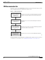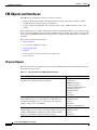
1
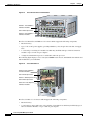
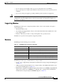
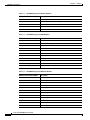
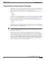
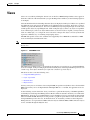
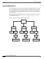
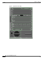
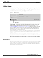
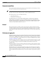
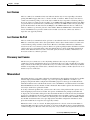
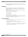
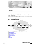
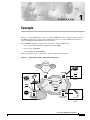
1
C H A P T E R
Concepts
The Cisco Catalyst 8500 router is a Layer 3–enhanced ATM switch that seamlessly integrates Layer 3
and ATM switching into a single chassis. Additionally, the Cisco Catalyst 8500 switch provides an
integrated ATM and Gigabit Ethernet network solution.
The C8500MGR application supports three of the Cisco Catalyst 8500 routers:
•
Cisco Catalyst 8510 multiservice ATM switch router (MSR)
•
Cisco Catalyst 8540 MSR
•
Cisco LightStream 1010 (LS1010)
The following figure shows a typical Cisco Catalyst 8500 router deployment.
Figure 1-1
Typical Cisco Catalyst 8500 Router Deployment
Internet
PSTN
Private
line
Router
PBX
IP
Branch
Router
ATM core
PBX
Catalyst 8540
with ARM
Headquarters
Catalyst 8540
with ARM
80629
Video
Servers
Backup Data
Center
Cisco Catalyst 8500 Manager User Guide
1-1
Chapter 1
The Concepts chapter describes EM concepts and covers the following information:
•
EM Documentation Set
•
Cisco EMF Software Features
•
EM Software Features
•
EM Objects and Interfaces
•
Views
•
Object States
Cisco Catalyst 8500 Manager User Guide
1-2
Concepts
Chapter 1
Concepts
EM Documentation Set
EM Documentation Set
This guide is one part of the C8500MGR EM documentation set. The following figure displays all of the
guides in the EM documentation set and details the contents of each.
Figure 1-2
EM Documentation Set
Cisco Element Management
Framework Installation and
Administration Guide
(Version 3.2)
Describes how to install the Cisco Element Management Framework
application and provides additional setup and licensing information
Cisco Element Management
Framework User Guide
(Version 3.2)
Describes how to use the Cisco Element Management Framework
application
Cisco Catalyst 8500
Manager User Guide
(Release 1.0)
Describes how to install the Cisco Catalyst 8500 Manager application
and provides additional setup information
Describes how to use the Cisco Catalyst 8500 Manager application
80592
Cisco Catalyst 8500
Manager Installation Guide
(release 1.0)
The guides identified in the preceding figure are available from Cisco Systems. For further information
on obtaining Cisco documentation, see the “Obtaining Documentation” section on page -xvii.
Cisco Catalyst 8500 Manager User Guide
1-3
Chapter 1
Concepts
Cisco EMF Software Features
Cisco EMF Software Features
Cisco EMF provides a flexible framework which supports a variety of EM applications, making it
possible to manage multiple device types within a given network on a single system. Common network
management functionality provides for complete management of the logical and physical components of
the network. Using a solid base, Cisco EMF provides vital core functionality which allows for optimal
network management when combined with EMs. Features include the following:
•
Map Viewer—Displays the contents of the managed device(s) and serves as the primary entry point
for the EM application, allowing for enhanced object monitoring status for all network elements
within the managed network
•
Deployment templates—Provides object deployment prompts, increasing ease and consistency
•
Auto Discovery—Allows for the automatic discovery of devices entering the network based on IP
and/or SNMP data
•
Event Browser—Notifies the system of events (e.g., alarms) which occur on the managed network
and, in turn, notifies the network manager according to adjustable settings
•
Object Group Manager—Enables you to organize managed objects which relate to one another into
groups
•
Performance manager—Presents performance statistics for monitored objects in a variety of formats
according to the criteria selected
•
User Access Control—Administration tool allowing system administrators to manage application
privileges per user and user passwords
•
Query Editor—Provides custom filtering capabilities which include or exclude certain information
from writing to the database and enables object group management
•
Notification Profiles—Warns the user of system events according to defined environmental
occurrences through an audible or visual indicators (e.g., beep, display pop–up window), scripts
(which, for example, sends an e–mail message), or event generation
•
Thresholding Regimes—Defines a set of polling attributes and the polling period for monitoring,
which, when met, run the applicable notification profiles
•
Event Groups—Organizes events by managed object(s) according to query settings
For further information on Cisco EMF and the tools it provides, see the following items:
•
The “Cisco EMF Launchpad” section on page 2-5
•
The Cisco Element Management Framework User Guide Release 3.2
•
Cisco EMF help windows available through the Help button or menu on the Cisco EMF Launchpad
Cisco Catalyst 8500 Manager User Guide
1-4
Chapter 1
Concepts
EM Software Features
EM Software Features
Installed with Cisco EMF, the EM allows for precise management of the device(s) it supports through
custom GUI windows and modeling behavior. Invoked from the Cisco EMF Map Viewer application, the
EM provides Fault, Configuration, Accounting, Performance, and Security (FCAPS) windows on
chassis, module, interface, and connection levels as applicable. These windows provide the features
which compliment the Cisco EMF capabilities to provide for complete, efficient network management.
Specifically, the C8500MGR supports the Cisco Catalyst 8500 routers, including the Cisco MSR 8540,
Cisco MSR 8510, and the Cisco LightStream 1010 (LS1010). C8500MGR supports various modules,
such as ATM, Gigabit and Fast Ethernet modules; and ATM, Ethernet, IP, and SONET interfaces.
Element management capabilities for these items are provided in windows and wizards, eliminating the
need for operators to have detailed Cisco IOS software and SNMP–based knowledge for individual
interface or system parameter commands.
The following features highlight the capabilities of the EM:
•
Framework—Based on Cisco EMF 3.2, which includes FCAPS management tools
•
IOS Versions—See the corresponding release note document for specific versions supported
•
Deployment and Discovery—Allows for manual or automatic deployment and discovery
– Deployment—Supports manual deployment for generic objects, and pre–deployment of chassis
objects using templates which provide faster deployment with fewer errors
– Auto Discovery—Discovers chassis and all submodules automatically within a given IP range,
providing real–time information regarding the contents of the network
•
Synchronization—Synchronizes the physical inventory model with managed NEs, providing
accurate, real–time information on what is deployed in the network
•
Fault management—Provides status information, as well as fault detection, troubleshooting, and
repair tools
•
Configuration—Provides base configuration for managed objects within the device, as well as:
– Discovery—Allows for discovery of individual chassis and modules, or complete subchassis
discovery
– ATM Provisioning—Logical inventory reflects real time provisioning
– Restoration—Configuration backup functionality is available, enabling configuration
restoration as required
– Redundancy—Dual CPUs allow for fail–over backups and provide forced fail–over capabilities
when needed
– Profiles—Allows you to apply established configuration parameters to a bulk number of objects
•
Accounting—Provides real–time inventory information
•
Performance—Supplies real–time performance–related statistics for modules, interfaces, and
connection, as well as capabilities to log historical performance data for analysis
•
Security—Provides capabilities to manage system security at the EM or device level
•
Alarm Notification—Provides support of multiple traps, producing alarm notification per the
criteria established
Cisco Catalyst 8500 Manager User Guide
1-5
Chapter 1
Concepts
EM Objects and Interfaces
EM Objects and Interfaces
The EM manages both physical and logical objects as follows:
•
Physical—Represents tangible components and devices such as the chassis (hardware frame),
module interfaces and port adapters, and interfaces
•
Logical—Represents intangible, more abstract features, such as ATM connections objects and
profiles
Fault, Configuration, Accounting, Performance, and Security (FCAPS) windows are accessible on both
physical and logical EM objects, in the form of FCAPS menu options that appear when you right–click
on any object in the EM. FCAPS functionality provides a complete management interface to features of
the router.
This section covers the following areas:
•
Physical Objects
•
Cisco Catalyst 8500 Router Chassis
•
Supporting Modules
•
Modules
•
Physical Interfaces and Logical Interface Technologies
•
Logical Objects
Physical Objects
The following table lists all physical objects created in the EM and the management functions that can
be performed on each object.
Table 1-1
Physical Objects and Management Functions
Physical Object
Management Functions
Chassis—The hardware frame of the Cisco Catalyst 8500 router,
which houses all subchassis objects (modules)
Management Information
Configuration
SNMP Management
IOS Image Download
Configuration Backup/Restore
Profile Management
Fault Management
Inventory
Performance
Processor Cards—The Cisco Catalyst 8500 routers support switch
fabric and router processor cards. The Cisco 8540 chassis can
accommodate multiple processor cards where one card is the
primary and up to two are redundant.
Configuration
Fault Management
Inventory
Performance
Redundancy Status/Failover
Modules—Modules may be either module interfaces or port
adapters. There are various types of modules within a chassis (for
example, ATM, Ethernet, and Generic). Each of these modules
support a given number of physical interfaces (ports).
Configuration
Fault Management
Inventory
Performance
Cisco Catalyst 8500 Manager User Guide
1-6
Chapter 1
Concepts
EM Objects and Interfaces
Table 1-1
Physical Objects and Management Functions (continued)
Physical Object
Management Functions
Physical Interfaces—Each module (interface or port adapter) has at
least one, if not multiple, physical interfaces (ports). The type of
physical interface is equivalent to the type of module the interface
resides on. Each different physical interface can support multiple
technologies (for details, see the “Physical Interfaces and Logical
Interface Technologies” section on page 1-11). The module type
determines what technologies reside on the interfaces.
Configuration
Fault Management
Performance
Configuration Profile
Inventory
Inventory
Supporting Modules—Additional subchassis cards and modules
which include switch fabric cards (SFCs), AC or DC power supply
module(s), and fan tray modules.
The physical objects and interfaces in the preceding table are organized as follows:
•
The chassis contains the modules, including supporting modules (e.g., processors, SFCs, power
supplies, and fan trays);
•
The modules contain the physical interfaces.
For further details on hierarchies within Cisco EMF and the EM, see the “Views” section on page 1-13.
Tip
Physical objects contained within a chassis are often referred to as subchassis objects or
modules.
Cisco Catalyst 8500 Router Chassis
The C8500MGR application supports three Cisco Catalyst 8500 router models:
•
Cisco 8510 multiservice ATM switch router (MSR)
•
Cisco 8540 MSR
•
Cisco LightStream 1010 (LS1010)
The Cisco 8510 and Cisco LS1010 chassis are exactly the same. The following figure displays an
example of the Cisco 8510 and Cisco LS1010 router chassis, and identifies the modules and
sub–modules that you would find.
Cisco Catalyst 8500 Manager User Guide
1-7
Chapter 1
Concepts
EM Objects and Interfaces
Figure 1-3
Cisco 8510 and Cisco LS1010 Chassis
Slots 0-1: Port adapters/
Interface modules
100Mbps Tx
100Mbps Tx
LINK Rx
100 Base Fx
FAST ETHERNET MODULE
LINK Rx
1
S
1
2
100Mbps Tx
TU
AT
ST
RE
SE
100Mbps Tx
LINK Rx
2
100Mbps Tx
AT
100Mbps Tx
LINK Rx
100Mbps Tx
LINK Rx
1
US
LINK Rx
100Mbps Tx
LINK Rx
5
100Mbps Tx
100Mbps Tx
LINK Rx
6
LINK Rx
100Mbps Tx
100Mbps Tx
LINK Rx
7
LINK Rx
100Mbps Tx
LINK Rx
8
LINK Rx
100Mbps Tx
LINK Rx
T
100Mbps Tx
100 Base Fx
FAST ETHERNET MODULE
4
100Mbps Tx
LINK Rx
4
100Mbps Tx
LINK Rx
US
2
3
Slots 3-4: Port adapters/
Interface modules
100Mbps Tx
LINK Rx
3
100Mbps Tx
A
ST
LINK Rx
Slot 2: Route processor
100Mbps Tx
0
100Mbps Tx
LINK Rx
100Mbps Tx
LINK Rx
4
100Mbps Tx
ST
LINK Rx
100Mbps Tx
LINK Rx
3
LINK Rx
100Mbps Tx
LINK Rx
5
100Mbps Tx
100Mbps Tx
LINK Rx
LINK Rx
100Mbps Tx
LINK Rx
6
100Mbps Tx
LINK Rx
100Mbps Tx
LINK Rx
7
100Mbps Tx
LINK Rx
LINK Rx
8
100Mbps Tx
LINK Rx
The Cisco 8510 and Cisco LS1010 are 5 slot chassis which support the following components:
•
Internal fan tray
•
Up to 2 AC or DC power supplies, providing redundancy or back–up in the event that one supply
fails
•
1 card carriage consisting of 4 module slots which may be filled with up to 4 full–slot interface
modules or up to 8 half–slot port adapters
•
A single board which incorporates 1 switch fabric and route processor
The following figure displays a Cisco Catalyst 8540 MSR router chassis, and identifies the modules and
sub–modules that you would find.
Cisco 8540 Chassis
M
CD
T
C
TX
-DE
-SE
T
RX
OP
-SE
-DE
C
RX
M
AR
AL
TX
RX
RX
FU
DU LLPL
EX
GIGABIT ETHERNET 16K
OCT-12 ATM SMF-IR 256k
GGIGABIT EHTERNET 16K
TX
LFUL LEX
DUP
K
LIN
RX
C/D
TX
CD
M
FU
DU LLPL
EX
GIGABIT ETHERNET 16K
RX
Slots 0-3: Port adapters/
Interface modules
OP
Figure 1-4
RX
C
DET
SYN
TX
1
3
4
5
OP-
RX-
RX
TX
6
7
8
9
10
11
12
6
7
8
9
10
11
12
ST
AT
US
2
US
FAST ETHERNET SWITCHING MODULE
2
3
4
ST
AT
1
5
FAST ETHERNET SWITCHING MODULE
Slot 4: Route processor
N
FA
US
AT
ST
T
SE
RE
2
PS
1
PS
TX
T2
SLO
T1
RX
K
LIN
SWITCH/PROCESSOR
X
AU
SLO
t
Ene
IA
MC
PC
CT
EJE
Slots 5-7: Switch processors
TX
T2
SLO
T1
RX
K
LIN
X
AU
SLO
IA
MC
PC
CT
EJE
0
TX
RX
P3
UT
RX
0
TX
P3
UT
1
TX
RX
P3
UT
RX
P3
UT
TX
TX
TX
13
RX
12
LIN RX
K
11
TX
TX
TX
10
LIN
K
9
LIN RX
K
8
LIN RX
K
7
LIN RX
K
TX
TX
6
LIN RX
K
5
3
0
TX
1
TX
TX
2
3
TX
P3
UT
RX
2
TX
UTP
TX
TX
2
TX
UTP
LIN RX
K
4
LIN RX
K
3
LIN RX
K
LIN RX
K
TX
TX
LIN RX
K
LIN RX
K
TX
1
TX
2
LIN RX
K
US
TX
AT
TX
LIN RX
K
LIN RX
K
ST
Slots 9-12: Port adapters/
Interface modules
1
TX
t
Ene
ROUTE SWITCH
OC3/STM1
MMF MODULE
TX
T
SE
RE
C85MS-18F-OC3MM
LIN RX
K
N
FA
2
PS
1
PS
US
AT
ST
SWITCH/PROCESSOR
LIN RX
K
Slot 8: Route processor
P3
UT
RX
UTP
RX
P3
UT
RX
P3
UT
3
0
TX
1
TX
TX
P3
UT
RX
2
TX
P3
UT
RX
P3
UT
RX
UTP
RX
P3
UT
RX
P3
UT
P3
UT
RX
3
TX
P3
UT
RX
TX
P3
UT
RX
o
o
The Cisco 8540 is a 13 slot chassis which supports the following components:
•
Internal fan tray
•
2 card carriages, upper and lower, each consisting of 4 module slots which may be filled by up to 4
full–slot interface modules or up to 8 half–slot port adapters
Cisco Catalyst 8500 Manager User Guide
1-8
Chapter 1
Concepts
EM Objects and Interfaces
Caution
•
Up to 2 route processor modules, where 1 processor is the primary and 1 is redundant
•
Up to 3 switch processor modules (Switch Fabric Cards), where 2 processors are primary and 1 is
redundant
•
Up to 2 AC or DC power supplies, providing redundancy in the event that one supply fails
Do not mix power supplies within the Cisco Catalyst 8540. In multiple power supply system
configurations, all power supplies must be of the same type (either 2 AC–input power supplies or 2
DC–input power supplies).
Supporting Modules
The EM supports three types of supporting modules within a chassis. Some modules only apply to
certain chassis types.
•
SFC (Switch Fabric Card)
•
AC or DC Power Supply Module—Chassis can be ordered with either dual–redundant AC or DC
power supply modules.
•
Fan Tray—The fan tray circulates cooling air through the card cage in the chassis.
The EM does not provide for management of supporting modules.
Modules
The EM supports the following processor modules.
Table 1-2
C8500MGR Supported Processor Modules
Processor Sub Module
Description
C8545MSR-MRP3CLK
C8540 multiservice router processor stratum 3
C8545MSR-MRP4CLK
C8540 multiservice route processor
C8546MSR-MSP-FCL
C8540 multiservice switch processor with ATM FC
C8515-MSRP
C8510 multiservice switch route processor
L1010-ASP-C-FC-1
LS1010 ATM switch processor with FC-per-class queuing
L1010-ASP-C-FCPFQ
LS1010 ATM switch processor with FC-per-flow queuing
The EM supports three types of module interfaces and port adapters:
•
Generic—For a complete listing of the Generic module interfaces and port adapters the EM supports
see Table 1-3.
•
ATM (Asynchronous Transfer Mode)—For a complete listing of the ATM module interfaces and
port adapters the EM supports see Table 1-4.
•
Ethernet (Fast or Gigabit)—Fast Ethernet supports data transfer rates of 100 Mbps; Gigabit Ethernet
supports data transfer rates of 1000 Mbps (or 1 Gigabit). For a complete listing of the Ethernet
module interfaces and port adapters C8500MGR supports see Table 1-5.
Cisco Catalyst 8500 Manager User Guide
1-9
Chapter 1
Concepts
EM Objects and Interfaces
Table 1-3
C8500MGR Supported Generic Modules
Module Interface/Port Adapter
Description
C85MS–4E1–FRRJ48
C8500 4–port E1 Frame–Relay PAM
C85MS–SCAM–2P
C8540 SuperCAM for Port Adapter Modules (PAMs)
WAI–E1C–4BNC
4 Port E1 (circuit emulation) BNC PAM
WAI–E1C–4RJ48
4 Port E1 (circuit emulation) RJ–48 PAM
WAI–T1C–4RJ48
4 Port T1 (circuit emulation) RJ–48 PAM
Table 1-4
C8500MGR Supported ATM Modules
Module Interface/Port Adapter
Description
C8540–ARM2
C8540 Enhanced ATM Router Module
C85MS–16F–OC3MM
C8540 MSR – 16–port OC–3 MMF – Installed
C85MS–4F–OC12MM
C8540 4–port OC–12 MMF
C85MS–4F–OC12SS
C8540 MSR 4–port OC–12 SMF Intermediate Reach – install
WAI–E1–4BNC
4 Port E1 (ATM) BNC PAM
WAI–E3–4BNC
4 Port E3 BNC PAM
WAI–OC3–4SS
4 Port OC–3c/STM–1 SMF–IR PAM
WAI–OC3–1S3M
OC–3c/STM–1 Mix PAM, 1–port SMF–IR + 3–port MMF
WAI–OC3–4MM
4 Port OC–3c/STM–1 MMF PAM
WAI–OC12–1SS
1 Port OC–12c/STM–4c SMF–IR PAM
WAI–T3–4BNC
4 Port DS–3 PAM
Table 1-5
C8500MGR Supported Ethernet Modules
Module Interface/Port Adapter
Description
C85EGE–2X–16K
C8540 2–port Enhanced GE 16K
C85EGE–2X–64K
C8540 2–port Enhanced GE 64K
C85EGE–2X–256K
C8540 2–port Enhanced GE 256K
C85GE–8X–64K
C8540 8–port GE Module 64K
C85FE–16F–16K
C8540 16–port 100–FX MT–RJ 16K
C85FE–16F–64K
C8540 16–port 100–FX MT–RJ 64K
C85FE–16FACL–16K
C8540 16–port 100–FX MT–RJ w/ ACL 16K
C85FE–16FACL–64K
C8540 16–port 100–FX MT–RJ w/ ACL 64K
C85FE–16T–16K
C8540 16–port 10/100 RJ–45 64K
C85FE–16T–64K
C8540 16–port 10/100 RJ–45 64K
C85FE–16TACL–16K
C8540 16 port 10/100 RJ45 w/ ACL 16K
C85FE–16TACL–64K
C8540 16–port 10/100 RJ45 w/ ACL 64K
Cisco Catalyst 8500 Manager User Guide
1-10
Chapter 1
Concepts
EM Objects and Interfaces
Physical Interfaces and Logical Interface Technologies
Physical interfaces and logical interface technologies are modeled as objects below a parent module. As
mentioned before, the type of module characterizes the type of interface. Interface types further break
down into two categories, physical interfaces and logical interface technologies.
Physical interfaces are the ports which exist on line cards. This EM supports the following physical
interfaces:
•
Ethernet
•
SONET
The EM handles both SDH and SONET in the same manner. The routers support both SDH and SONET.
For a comparison chart of SONET and SDH speeds, see Appendix B, “SONET/SDH Conversion Chart.”
Logical interface technologies represent the communication between two network devices. Logical
interface technologies allow for virtual connections, such as PVCs and SPVCs. This EM supports the
following logical interface technologies:
•
ATM
•
IP
Physical interfaces and logical interface technologies are classified as ‘‘interfaces’’ within this EM, and,
therefore, are referred to as such within this guide. Keep in mind the differences previously described as
you manage the interfaces within your network.
Tip
The technologies an interface supports are accessible within FCAPS–based management windows.
It is important to understand that physical interfaces require logical interface technologies in order
to fully manage an interface.
The following table outlines each interface type and the applicable physical and logical interface
technologies supported. Also included are the different FCAPS service windows that are applicable to
each physical and logical interface technology. For example, if you want to configure an ATM interface
type, look in the table under ATM, and you will notice that three physical interface and logical interface
technologies apply: ATM, SONET, and IP. This means that to fully configure an ATM over SONET
interface, for example, you should open and update the appropriate fields in all the physical and logical
configuration windows to completely configure a SONET interface which supports ATM technology.
Note that the shaded areas denote logical interface technologies.
Cisco Catalyst 8500 Manager User Guide
1-11
Chapter 1
Concepts
EM Objects and Interfaces
Table 1-6
Physical Interfaces, Related Technologies and Windows
Interface Type
Physical and Logical
Interface Technologies
Ethernet
Ethernet
Configuration
Status
Performance
Profile
IP
Configuration
SONET
Status
Performance
ATM
Fault
Configuration
Status
Performance
Profile
IP
Configuration
SONET
FCAPS Service Windows
Although not technology–specific, physical or logical, generic support is available through
Configuration, Status, and Performance windows for each of the interface types in the preceding table.
Logical Objects
The EM supports one logical object type, ATM connections. ATM connections may be Permanent
Virtual Circuits (PVCs), Soft Permanent Virtual Circuits (SPVCs), or Switched Virtual Circuits (SVCs)
that can be applied to ATM interfaces.
The following table describes the management functions for ATM logical objects.
Table 1-7
ATM Logical Objects
Logical Object
Management Functions You Can Perform
PVC
Upload, create, configure, manage, and delete on main or sub–interfaces.
Status information can be collected and displayed for VCL objects only.
SPVC
Upload, create, configure, manage, and delete on main or sub–interfaces.
Cisco Catalyst 8500 Manager User Guide
1-12
Chapter 1
Concepts
Views
Views
Views are accessible by clicking the Viewer icon on the Cisco EMF launchpad. These views appear in
the frame at the left of the window when you open the Map Viewer window (see the following figure for
an example).
Views model hierarchical relationships between objects, both physical and logical. Objects are organized
into different views and can exist in multiple views simultaneously by reference. Each object can have
a number of parent and child objects. You can access EM objects by navigating through one of the views
to find specific objects by expanding the text. Click on the plus sign (+) next to any object to expand the
view. A minus sign (–) next to an object indicates there are no more levels to expand; you may, however,
click on a minus sign (–) to collapse the view to the level of the specific object as necessary. Each view
represents a different way of containing and grouping objects.
The EM adds specific views to the standard views supplied by Cisco EMF. The standard Cisco EMF
views are the Physical and Network views.
Note
For further information on views, see the Cisco Element Management Framework User Guide
Release 3.2.
Figure 1-5
C8500MGR Views
The number in parenthesis next to a view indicates how many top–level objects are contained within the
view. For example, in the preceding figure the Network, Physical, and Component Managed views each
contain 1 top–level object and the Layer 3 QoS view contains 2 top–level objects.
The Views section covers the following areas:
•
Component Managed View
•
Layer 3 QoS View
•
Network View
•
Physical View
You may or may not see all of these views using this EM (exceptions noted). These views all exist within
EMs, however they are not all implemented. If multiple EMs are co–resident, the applicable views are
displayed.
As the following sections detail, the views you will use to perform the majority of the EM capabilities
are the Physical and Component Managed views. Both a similar in structure and allow you to initiate the
EM windows, however it is recommended that you use the Physical view to perform most management
functions within the EM. The Physical view provides a graphical representation of the chassis that the
Component Managed view does not. It should, however, be noted that you must use the Component
Managed view to see representative ATM connection objects within the EM as ATM connection objects
are not available through the Physical view.
Cisco Catalyst 8500 Manager User Guide
1-13
Chapter 1
Concepts
Views
Component Managed View
The Component Managed view displays all objects within the Cisco EMF system. For example, say you
have two types of EM applications installed in Cisco EMF: EM A and EM B. Information for both the
EM A and EM B display within the Component Managed view. Additionally, the Component Managed
view also displays ATM connections such as PVCs and SPVCs. Connection objects are not visible in any
other view. However, it is not recommended to work within this view unless you have multiple EM
applications installed.
The Component Managed view and Physical view have the same basic hierarchy structure, as shown in
the following figure. Note that the Physical view does not display logical ATM connections like the
Component Managed view does.
Figure 1-6
Hierarchy of Component Managed and Physical Views
Site
Supporting
modules
Line cards
Supporting
modules
Line cards
Cisco chassis
Supporting
modules
Line cards
Physical
interfaces
Physical
interfaces
Physical
interfaces
Logical connections
(PVC and SPVCs)
Logical connections
(PVC and SPVCs)
Logical connections
(PVC and SPVCs)
Cisco Catalyst 8500 Manager User Guide
1-14
Cisco chassis
80564
Cisco chassis
Chapter 1
Concepts
Views
Layer 3 QoS View
The Layer 3 QoS view displays only Layer 3 QoS objects within the EM, such as the following:
•
Access Lists
•
Committed Access Rate (CAR) objects
•
Weighted Random Early Detection (WRED) objects
You can work within this view to create and configure Access Lists or CAR or WRED objects by
accessing the respective EM menus.
C8500MGR does not provide Layer 3 QoS support. Neither the Layer 3 QoS view nor the respective
menus are applicable to the C8500MGR.
Network View
This view displays all network devices within their relevant networks and subnets. The auto–discovery
system of Cisco EMF uses this view to determine which devices exist on the system so that it does not
try to discover the same device multiple times. For details on auto–discovery, see the “Automatically
Discovering Chassis” section on page 3-2.
Physical View
Objects in the Physical view are ordered according to their relative physical location. The Physical view
defines physical containment relationships, meaning that each object is defined according to which
object it is contained within. For example, a site is located under the Physical view; a chassis is contained
under a site; and sub modules and supporting modules are contained within a chassis.
See the previous figure for an overview of the structure of the Physical view.
The Physical view also provides chassis maps, which are graphical representations of the chassis and its
contents. You can access management menus on objects within chassis maps. To display a chassis map,
simply click on the chassis object for the router you wish to view.
Cisco Catalyst 8500 Manager User Guide
1-15
Chapter 1
Views
Figure 1-7
Physical View Chassis Map
Cisco Catalyst 8500 Manager User Guide
1-16
Concepts
Chapter 1
Concepts
Object States
Object States
Object states reflect the life cycle of an object. Whatever stage the object is in at any given time displays
in the state type. The state of an object can change frequently, depending upon what actions take place
on the object. All objects within the EM are in a specific state which appears at the bottom left corner
of each FCAPS window. The following figure highlights an object’s state.
Figure 1-8
EM Object States
Object State
The two most common object states are Normal and Decommissioned. For example, when you deploy a
module in the EM, the initial state of the module is decommissioned. You can then commission the
module to begin active management. (For instruction on how to commission a module, see the
“Commissioning Modules” section on page 3-40 or on page 5-44.) When you commission the module,
it passes through two transitory states: discovery, then commissioning. The commissioning process
determines which state to move the object into (typically Normal). This example reflects the basic
process of deploying and commissioning an object.
Certain states ripple down to objects below. For example, if you decommission a chassis, all subchassis
objects also decommission. If you enable performance logging on a module, all interfaces under the
module also enable.
By default, FCAPS windows refresh at a rate dependent upon the type of window. For example,
inventory windows refresh at a lower rate than performance windows. The average refresh rate is every
30 seconds.
The following sections describe the possible states that an object may be in and provides a description
of these states.
Normal State
The normal state indicates that an object is operational. When an object enters the normal state, the EM
performs heartbeat polling on objects at varying intervals to determine whether their presence and to
current state. For instance, chassis presence polling occurs every minute while module and interface
presence polling occurs every five minutes.
Cisco Catalyst 8500 Manager User Guide
1-17
Chapter 1
Concepts
Object States
Decommissioned State
The decommissioned state indicates that an object is not managed. When you manually deploy an object,
the object is normally put into the decommissioned state.
Tip
Initially deployed objects are decommissioned to leave you with the option of managing
the object or not. If you want to manage the object, you must commission the object.
The following actions occur on a decommissioned object:
•
Active management stops
•
All sub objects also decommission
Decommission buttons are located in Chassis, Module, Interface, and Connection Configuration
windows. When you decommission an object, any children of that object also change their state to
decommissioned. For example, if you decommission a chassis, all objects within that chassis (modules,
interfaces, and connections) also decommission. If you decommission a module, all interfaces and
connections on that module decommission, and so on.
Errored
If the operational status of a module goes down, it moves into the errored state. In the errored state,
performance polling (if active) stops; however, heartbeat polling (which polls an object every 5 minutes
to verify its existence and current state) continues until the device responds positively to a heartbeat
request. When the module responds positively to heartbeat requests, it moves back into the previously
held state.
Performance Logging On
Enabling performance logging on for an object in the Normal state moves the object into the performance
logging on state. This means that performance data collection for the object begins and is available for
review in the Cisco EMF Performance Manager window. Regardless of whether performance logging is
on or off for a particular object, current performance data is available in the EM Performance windows
as Chapter 8, “Performance”, describes.
Performance logging collects data for interfaces only. You can enable performance logging on a global
scale or on an individual object basis. Enabling global performance logging puts all subchassis objects
into a performance logging on state. However, remember that only interfaces actually collect
performance data.
Performance logging occurs every 15 minutes. This means that when you enable performance logging
or global performance logging initially on an object, at least one 15–minute increment must pass before
data displays in the Performance Manager.
Heartbeat polling occurs on objects in the performance logging on state. If the object moves into the
errored state, it returns to the performance logging on state when the error is rectified. For example, if a
module is in the performance logging on state and it goes down, it moves into the errored state. When
heartbeat polling finds that the module is back up, it restores the module to the performance logging on
state.
Cisco Catalyst 8500 Manager User Guide
1-18
Chapter 1
Concepts
Object States
Lost Comms
The lost comms (lost communications) state indicates that the object is not responding to heartbeat
polling. The EM can apply this state to a chassis, module, or interface. When an object is in the lost
comms state, heartbeat polling occurs on the object. When the object responds to heartbeat polling, it
moves out of the lost comms state. For example, say an ATM module in the EM was predeployed. When
you perform device synchronization (commissioning a chassis), the ATM module is not yet physically
present in the hardware. In this situation, the EM places the ATM module into the lost comms state,
where it continues to poll for the presence of the module. When the ATM module is inserted into the
chassis, the EM detects its presence and moves the module out of the lost comms state and into a
respective state (typically normal).
Lost Comms No Poll
The lost comms (lost communications) no poll state occurs when the router is not contactable. When the
EM loses connectivity with a device, the representative chassis object remains in the lost comms state
so that heartbeat polling continues on the chassis. However, all modules and interfaces within that
chassis move into a lost comms no poll state. There is no point in polling modules and interfaces within
a device that is not contactable. If the connection with the device is down, all modules and interfaces
will be down. When the device becomes contactable again, the chassis, modules, and interfaces are
moved out of the lost comms no poll state.
Discovery Lost Comms
The discovery lost comms state occurs only during subchassis discovery. If, for example, you
commission a chassis (which begins the process of subchassis discovery) and a module discovers with a
faulty connection, the module goes into the discovery lost comms state. When connectivity establishes
with the corresponding object in the device, subchassis discovery resumes, and the object moves out of
the discovery lost comms state.
Mismatched
The mismatched state occurs when a mismatch is found between what hardware is in the device and that
which is deployed in the EM. For example, say you are expecting an ATM OC–3 module so you
predeploy and perform offline configuration in the EM to prepare for that type of module. However,
when the module becomes available in the chassis, it is not an ATM OC–3 module but an OC–12 module.
When the EM detects the new module, it finds a mismatch. The module is put into the mismatch state
and a major alarm raises against the module.
To rectify a mismatch problem, first you must assess the source of the problem. If the operator was at
fault and predeployed an incorrect module, the operator should delete the predeployed module and
re–deploy the correct module. If the person who inserted the module is at fault because they inserted the
wrong type of module into the chassis, the module should be removed. When you remove a module, the
EM moves the module into a lost comms state. Inserting the correct module enables the EM to find the
new module and download the correct pre–deployment and offline configuration information, then
places the module into its respective state (typically normal).
Mismatch can also occur on a chassis. If, during deployment of a chassis, an incorrect IP address is
entered, the EM cannot discover the chassis due to an erroneous IP address that was entered during the
commissioning process. Because of this, discovery fails, a major alarm is raised against the chassis, and
Cisco Catalyst 8500 Manager User Guide
1-19
Chapter 1
Concepts
Object States
the chassis enters the mismatched state. To rectify this problem, you must either delete the predeployed
chassis and deploy the correct one, or fix the IP address by re–entering the correct one in the chassis
Management Information window.
Synchronizing
The EM provides capabilities to synchronize hardware components and settings between the
management system (EM) and the device. By default, the device is the master in the synchronization
policy. Therefore, synchronization mirrors the settings on the device to the management system;
overwriting any existing data.
Synchronization can be extremely useful when a device has been operational for some time and the
Cisco EMF management system is available to manage it.
Synchronizing occurs as a result of the following actions:
•
Chassis commissioning
•
Manual synchronization
•
Auto synchronization
Manual synchronization is not available in C8500MGR.
When an object deploys and initially commissions, the state changes to discovery, then normal, then
synchronizing. When the management system and device complete synchronization, the state changes
to the appropriate post–commissioning state (typically normal).
Transient Object States
Certain states in the EM are temporary or transient, that is, they exist only for a short time while a process
is underway. The following states are transient:
•
Download—Temporary state when a Cisco IOS Download is processing
•
Reset—Temporary state during a Cisco IOS Download, when the device reboots for the new image
to take effect
•
Discovery—Temporary state during subchassis discovery; during this stage, objects are discovering
•
Commissioning—Temporary state during subchassis discovery; during this stage, the EM is
determining which state to move each object into
Cisco Catalyst 8500 Manager User Guide
1-20