1
Cisco 6500/7600 Series Manager User
Guide
Release 2.1
Corporate Headquarters
Cisco Systems, Inc.
170 West Tasman Drive
San Jose, CA 95134-1706
USA
http://www.cisco.com
Tel: 408 526-4000
800 553-NETS (6387)
Fax: 408 526-4100
Customer Order Number:
THE SPECIFICATIONS AND INFORMATION REGARDING THE PRODUCTS IN THIS MANUAL ARE SUBJECT TO CHANGE WITHOUT NOTICE. ALL
STATEMENTS, INFORMATION, AND RECOMMENDATIONS IN THIS MANUAL ARE BELIEVED TO BE ACCURATE BUT ARE PRESENTED WITHOUT
WARRANTY OF ANY KIND, EXPRESS OR IMPLIED. USERS MUST TAKE FULL RESPONSIBILITY FOR THEIR APPLICATION OF ANY PRODUCTS.
THE SOFTWARE LICENSE AND LIMITED WARRANTY FOR THE ACCOMPANYING PRODUCT ARE SET FORTH IN THE INFORMATION PACKET THAT
SHIPPED WITH THE PRODUCT AND ARE INCORPORATED HEREIN BY THIS REFERENCE. IF YOU ARE UNABLE TO LOCATE THE SOFTWARE LICENSE
OR LIMITED WARRANTY, CONTACT YOUR CISCO REPRESENTATIVE FOR A COPY.
The Cisco implementation of TCP header compression is an adaptation of a program developed by the University of California, Berkeley (UCB) as part of UCB’s public
domain version of the UNIX operating system. All rights reserved. Copyright © 1981, Regents of the University of California.
NOTWITHSTANDING ANY OTHER WARRANTY HEREIN, ALL DOCUMENT FILES AND SOFTWARE OF THESE SUPPLIERS ARE PROVIDED “AS IS” WITH
ALL FAULTS. CISCO AND THE ABOVE-NAMED SUPPLIERS DISCLAIM ALL WARRANTIES, EXPRESSED OR IMPLIED, INCLUDING, WITHOUT
LIMITATION, THOSE OF MERCHANTABILITY, FITNESS FOR A PARTICULAR PURPOSE AND NONINFRINGEMENT OR ARISING FROM A COURSE OF
DEALING, USAGE, OR TRADE PRACTICE.
IN NO EVENT SHALL CISCO OR ITS SUPPLIERS BE LIABLE FOR ANY INDIRECT, SPECIAL, CONSEQUENTIAL, OR INCIDENTAL DAMAGES, INCLUDING,
WITHOUT LIMITATION, LOST PROFITS OR LOSS OR DAMAGE TO DATA ARISING OUT OF THE USE OR INABILITY TO USE THIS MANUAL, EVEN IF CISCO
OR ITS SUPPLIERS HAVE BEEN ADVISED OF THE POSSIBILITY OF SUCH DAMAGES.
CCIP, the Cisco Powered Network mark, the Cisco Systems Verified logo, Cisco Unity, Follow Me Browsing, FormShare, Internet Quotient, iQ
Breakthrough, iQ Expertise, iQ FastTrack, the iQ Logo, iQ Net Readiness Scorecard, Networking Academy, ScriptShare, SMARTnet, TransPath, and
Voice LAN are trademarks of Cisco Systems, Inc.; Changing the Way We Work, Live, Play, and Learn, Discover All That’s Possible, The Fastest Way to
Increase Your Internet Quotient, and iQuick Study are service marks of Cisco Systems, Inc.; and Aironet, ASIST, BPX, Catalyst, CCDA, CCDP, CCIE,
CCNA, CCNP, Cisco, the Cisco Certified Internetwork Expert logo, Cisco IOS, the Cisco IOS logo, Cisco Press, Cisco Systems, Cisco Systems Capital,
the Cisco Systems logo, Empowering the Internet Generation, Enterprise/Solver, EtherChannel, EtherSwitch, Fast Step, GigaStack, IOS, IP/TV,
LightStream, MGX, MICA, the Networkers logo, Network Registrar, Packet, PIX, Post-Routing, Pre-Routing, RateMUX, Registrar, SlideCast,
StrataView Plus, Stratm, SwitchProbe, TeleRouter, and VCO are registered trademarks of Cisco Systems, Inc. and/or its affiliates in the U.S. and certain
other countries.
All other trademarks mentioned in this document or Web site are the property of their respective owners. The use of the word partner does not imply a
partnership relationship between Cisco and any other company. (0203R)
Cisco 6500/7600 Series Manager User Guide
Copyright © 2001-2002, Cisco Systems, Inc.
All rights reserved.
C ON T E N T S
About this Guide
Audience
xi
xi
Organization
xi
Related Documentation
xii
Conventions and Terminology
xiii
Obtaining Documentation xiv
World Wide Web xiv
Documentation CD-ROM xiv
Ordering Documentation xiv
Documentation Feedback xv
Obtaining Documentation xv
World Wide Web xv
Documentation CD-ROM xv
Ordering Documentation xvi
Documentation Feedback xvi
Obtaining Technical Assistance xvi
Cisco.com xvi
Technical Assistance Center xvii
CHAPTER
1
Product Overview
1-1
Cisco 6500/7600 Series Manager Software Overview
Software Features 1-2
Catalyst 6000 Family Overview
Cisco 7600 Series Overview
CHAPTER
2
Supported Hardware
1-6
Supported Software
1-10
Basic Concepts
1-1
1-2
1-4
2-1
Cisco EMF and Cisco 6500/7600 Series Manager Software
Element Management 2-2
C65/76M Objects and Interfaces
Physical Objects 2-3
Logical Objects 2-4
2-1
2-3
Cisco 6500/7600 Series Manager User Guide
iii
Contents
Network Element Object
2-6
Containment Views 2-7
Network View 2-7
Physical View 2-8
C65/76M Object States 2-8
Decommissioned State 2-8
Discovery State 2-8
Normal State 2-9
Lostcomms State 2-9
Normal Lostcomms State 2-9
Performance State 2-9
Perflostcomms State 2-10
Discovery Lostcomms State 2-10
Mismatched State 2-10
CHAPTER
3
Getting Started
3-1
Preparing to Use the C65/76M Software
3-1
Using Cisco EMF 3-2
Cisco Element Management Framework Launchpad Window
Quitting a Cisco EMF User Session 3-6
Deploying C65/76M Objects
3-7
Launching Object Management Dialogs
CHAPTER
4
Deploying the C65/76M
3-3
3-10
4-1
Managing a Catalyst 6000 Family Switch or a Cisco 7600 Series Internet Router
Deploying Objects 4-1
Commissioning Objects 4-3
Deployment and Commissioning Process
IP Auto Discovery 4-5
Manual Deployment 4-11
Predeployment 4-21
CHAPTER
5
Physical Object Dialog Boxes
5-1
C6576M Chassis Dialog Box 5-3
Status Tab 5-3
Inventory Tab 5-6
Performance Tab 5-10
Additional Notes Tab 5-11
Cisco 6500/7600 Series Manager User Guide
iv
4-5
4-1
Contents
C6576M Power Supply Dialog Box
Details Tab 5-12
Additional Notes Tab 5-14
5-12
C6576M Supervisor Module Dialog Box
Status Tab 5-15
Inventory Tab 5-17
Performance Tab 5-19
Additional Notes Tab 5-20
C6576M Ethernet Module Dialog Box
Details Tab 5-22
Additional Notes Tab 5-26
C6576M Ethernet Interface Dialog Box
Status Tab 5-27
Configuration Tab 5-30
Performance Tab 5-33
Routing Protocol Tab 5-35
STP Tab 5-38
HSRP Tab 5-42
QoS Tab 5-45
Additional Notes Tab 5-48
5-15
5-22
5-27
C6576M Switch Fabric Module Dialog Box
Details Tab 5-49
Performance Tab 5-51
Additional Notes Tab 5-52
C6576M FlexWAN Module Dialog Box
Details Tab 5-53
Additional Notes Tab 5-55
C6576M Port Adapter Dialog Box
Details Tab 5-56
Additional Notes Tab 5-58
5-49
5-53
5-56
C6576M Optical Services Modules Dialog Box
Details Tab 5-60
Additional Notes Tab 5-64
5-60
C6576M SLB Dialog Box 5-65
Details Tab 5-65
Client Side VLAN Tab 5-68
Server Side VLAN Tab 5-70
Server Farms Tab 5-72
Virtual Servers Tab 5-74
Cisco 6500/7600 Series Manager User Guide
v
Contents
Additional Notes Tab
5-77
C6576M ATM T3 Interface Dialog Box
Status Tab 5-78
Configuration Tab 5-80
ATM/T3 Tab 5-82
Performance Tab 5-84
Routing Protocol Tab 5-87
Additional Notes Tab 5-89
5-78
C6576M ATM E3 Interface Dialog Box
Status Tab 5-90
Configuration Tab 5-92
ATM/E3 Tab 5-94
Performance Tab 5-95
Routing Protocol Tab 5-98
Additional Notes Tab 5-100
5-90
C6576M ATM SONET Interface Dialog Box
Status Tab 5-101
Configuration Tab 5-104
ATM/Sonet Tab 5-106
Performance Tab 5-108
Routing Protocol Tab 5-111
Additional Notes Tab 5-114
5-101
C6576M OSM GE-WAN Interface Dialog Box
Status Tab 5-115
Configuration Tab 5-117
Performance Tab 5-118
Routing Protocol Tab 5-121
HSRP Tab 5-124
Additional Notes Tab 5-127
5-115
C6576M OSM Channelized SONET Interface Dialog Box
Status Tab 5-128
Configuration Tab 5-131
Performance Tab 5-135
Additional Notes Tab 5-137
C6576M OSM POS Interface Dialog Box
Status Tab 5-138
Configuration Tab 5-140
ATM/SONET Tab 5-141
Performance Tab 5-143
Cisco 6500/7600 Series Manager User Guide
vi
5-138
5-128
Contents
Routing Protocol Tab 5-145
Additional Notes Tab 5-147
C6576M OSM Serial Subinterface Dialog Box
Status Tab 5-149
Interface Configuration Tab 5-151
DS-3 Configuration Tab 5-152
Performance Tab 5-156
DS-3 Statistics Tab 5-158
Routing Protocol Tab 5-160
Additional Notes Tab 5-162
C6576M OSM POS Subinterface Dialog Box
Status Tab 5-163
Interface Configuration Tab 5-165
POS Tab 5-167
Performance Tab 5-169
POS Statistics Tab 5-172
Routing Protocol Tab 5-173
Additional Notes Tab 5-176
CHAPTER
6
Logical Object Dialog Boxes
5-149
5-163
6-1
C6576M NE Config/Mgmt Dialog Box
Configuration Tab 6-3
System Information Tab 6-6
SNMP Tab 6-7
SNMP Trap Tab 6-8
Additional Notes Tab 6-12
6-3
C6576M Software Dialog Box 6-13
IOS Image Tab 6-13
Cat OS Image Tab 6-16
IOS Config File Tab 6-18
Cat OS Config File Tab 6-23
Additional Notes Tab 6-28
C6576M Syslog Dialog Box 6-29
IOS Tab 6-29
Catalyst OS Tab 6-31
Additional Notes Tab 6-33
C6576M VTP Dialog Box 6-34
Details Tab 6-34
Additional Notes Tab 6-36
Cisco 6500/7600 Series Manager User Guide
vii
Contents
C6576M VLAN Dialog Box 6-37
Status Tab 6-37
Configuration Tab 6-40
VLAN Membership Tab 6-41
Global Tab 6-43
STP Tab 6-45
QoS Tab 6-47
EoMPLS Tab 6-48
VLAN Database Tab 6-49
Additional Notes Tab 6-51
C6576M EtherChannel Dialog Box
Status Tab 6-52
Configuration Tab 6-54
Membership Tab 6-56
Routing Protocol Tab 6-58
STP Tab 6-59
HSRP Tab 6-63
Additional Notes Tab 6-67
C6576M BGP Dialog Box 6-68
BGP Tab 6-68
Neighbor Tab 6-71
Redistribution Tab 6-73
Distribution List Tab 6-75
Additional Notes Tab 6-77
C6576M OSPF Dialog Box 6-78
Details Tab 6-78
Area Tab 6-80
Network Tab 6-81
Global Tab 6-83
Neighbor Tab 6-85
Redistribution Tab 6-87
Distribution List Tab 6-89
Additional Notes Tab 6-91
C6576M EIGRP Dialog Box 6-92
Details Tab 6-92
Redistribution Tab 6-95
Distribution List Tab 6-97
Additional Notes Tab 6-99
C6576M IS-IS Dialog Box
Cisco 6500/7600 Series Manager User Guide
viii
6-100
6-52
Contents
Details Tab 6-100
Interfaces Tab 6-102
Redistribution Tab 6-104
Additional Notes Tab 6-105
C6576M NDE Configuration Dialog Box
Details Tab 6-106
NDE Filters Tab 6-108
Additional Notes Tab 6-110
6-106
C6576M STP Dialog Box 6-111
Details Tab 6-111
Additional Notes Tab 6-112
C6576M ACL Configuration Dialog Box
Details Tab 6-113
Additional Notes Tab 6-116
6-113
C6576M Loopback Dialog Box 6-117
Configuration Tab 6-117
Additional Notes Tab 6-118
C6576M QoS Dialog Box 6-119
Details Tab 6-119
Named Aggregate Tab 6-121
Class Maps Tab 6-124
Additional Notes Tab 6-126
C6576M QoS Policy Map Dialog Box
Policy Map Tab 6-127
Policy Map Classes Tab 6-129
Additional Notes Tab 6-134
CHAPTER
7
Profiles
6-127
7-1
Network Element Profile 7-1
Creating a Network Element Profile
Applying a Network Element Profile
Syslog Profile 7-3
Creating a Syslog Profile
Applying a Syslog Profile
CHAPTER
8
Alarms and Alarm Management
Viewing C65/76M Alarms
Event Browser 8-2
7-1
7-3
7-3
7-4
8-1
8-1
Cisco 6500/7600 Series Manager User Guide
ix
Contents
Full Event Description Dialog
C65/76M Alarms 8-5
SNMP Trap Alarms 8-6
Object State Alarms 8-9
Attribute Value Alarms 8-13
Cisco 6500/7600 Series Manager User Guide
x
8-4
About this Guide
This preface describes who should read the Cisco 6500/7600 Series Manager User Guide, how it is
organized, and its document conventions.
Audience
This guide is written as a technical resource for network managers, system administrators (the people
responsible for managing the network), network analysts (those who configure the network), and
operators.
It is assumed that you have a basic understanding of network design, operation, and terminology, and
that you are familiar with your own network configurations. It is also assumed that you have a basic
familiarity with UNIX and have read and understood the Cisco Element Management Framework User
Guide.
Organization
This guide is organized as follows:
Chapter
Title
Description
Chapter 1 Product Overview
Provides a context for the
Cisco 6500/7600 Series Manager.
Chapter 2 Basic Concepts
Describes basic concepts of the Cisco
Element Management Framework
(CEMF) and the concepts of network
and service management associated
with the C65/76M using CEMF.
Chapter 3 Getting Started
Describes the order of the tasks you
should perform to get started with the
C65/76M software.
Chapter 4 Deploying the C65/76M
Describes the deployment and
commissioning process for the
C65/76M.
Cisco 6500/7600 Series Manager User Guide
xi
About this Guide
Related Documentation
Chapter
Title
Description
Chapter 5 Physical Object Dialog
Boxes
Describes the C65/76M dialogs for
physical objects and the management
functions that can be carried out.
Chapter 6 Logical Object Dialog
Boxes
Describes the C65/76M dialogs for
logical objects and the management
functions that can be carried out.
Chapter 7 Profiles
Describes how to create and apply
C65/76M profiles.
Chapter 8 Alarms and Alarm
Management
Describes the alarms that are raised
in CEMF by the C65/76M.
Related Documentation
In addition to this guide, the following documents are available for the Cisco 6500/7600 Series Manager:
•
Cisco 6500/7600 Series Manager Installation Guide
•
Release Notes for the Cisco 6500/7600 Series Manager
The following documents are available for the Catalyst 6000 family switches:
•
Site Preparation and Safety Guide
•
Catalyst 6000 Family Quick Software Configuration Guide
•
Catalyst 6000 Family Module Installation Guide
•
Catalyst 6000 Family Software Configuration Guide
•
Catalyst 6000 Family System Functional Description
•
Catalyst 6000 Family Command Reference
•
Catalyst 6000 Family IOS Software Configuration Guide
•
Catalyst 6000 Family IOS Command Reference
•
ATM Software Configuration and Command Reference—Catalyst 5000 Family and Catalyst 6000
Family Switches
•
System Message Guide—Catalyst 6000 Family, 5000 Family, 4000 Family, 2926G Series, 2948G,
and 2980G Switches
The following documents are available for the Cisco 7600 Internet Router:
•
Site Preparation and Safety Guide
•
Cisco 7600 Internet Router Quick Software Configuration Guide
•
Cisco 7600 Internet Router Software Configuration Guide
•
Cisco 7600 Internet Router Command Reference
•
Cisco 7603 and 7606 Internet Router Installation Guide
•
Cisco 7609 Internet Router Installation Guide
•
Cisco 7600 Internet Router Module Installation Guide
•
Cisco 7600 Internet Router System Message Guide
Cisco 6500/7600 Series Manager User Guide
xii
About this Guide
Conventions and Terminology
For information about MIBs, refer to this URL:
http://www.cisco.com/public/sw-center/netmgmt/cmtk/mibs.shtml
Conventions and Terminology
This publication uses the following conventions:
Convention
Description
boldface font
Commands and keywords are in boldface. Names of
onscreen elements that you click or select are in
boldface. When describing user actions, keystrokes are
in boldface.
italic font
Arguments for which you supply values are in italics.
[ ]
Elements in square brackets are optional.
{x|y|z}
Alternative keywords are grouped in braces and
separated by vertical bars.
[x|y|z]
Optional alternative keywords are grouped in brackets
and separated by vertical bars.
string
A nonquoted set of characters. Do not use quotation
marks around the string or the string will include the
quotation marks.
screen
font
boldface screen
Terminal sessions and information the system displays
are in screen font.
Information you must enter is in boldface
screen
font.
font
italic screen font
Arguments for which you supply values are in italic
screen font.
^
The symbol ^ represents the key labeled Control—for
example, the key combination ^D in a screen display
means hold down the Control key while you press the D
key.
< >
Nonprinting characters, such as passwords are in angle
brackets.
Notes use the following conventions:
Note
Means reader take note. Notes contain helpful suggestions or references to material not covered in the
publication.
The Cisco EMF software supports a three-button mouse. The buttons are configured as follows:
•
Left button—Selects objects and activates controls.
•
Middle button—Adjusts a selected group of objects, adding to or deselecting part of the group.
•
Right button—Displays and selects from menus.
Cisco 6500/7600 Series Manager User Guide
xiii
About this Guide
Obtaining Documentation
This guide uses the following conventions and terminology:
•
pointer—Indicates where the mouse action is to occur.
•
select—To push and hold down the left mouse button.
•
release—To let up on a mouse button to initiate an action.
•
click—To select and release a mouse button without moving the pointer.
•
double-click—To click a mouse button twice quickly without moving the pointer.
•
drag—To move the pointer by sliding the mouse with one or more buttons selected.
In situations that allow more than one item to be selected from a list simultaneously, the following
actions are supported:
•
To select a single item in a list, click on the entry. Clicking a second time on a previously selected
entry deselects it.
•
To select a contiguous block of items, click on the first entry; then, without releasing the mouse
button, drag to the last desired entry and release. (A subsequent click anywhere on the screen
deselects all previous selections.)
•
To extend a currently selected block, hold the Shift key down and click on the entry at the end of
the group to be added.
•
To add a noncontiguous entry to the selection group, hold down the Ctrl (Control) key and click on
the entry to be added.
Obtaining Documentation
The following sections explain how to obtain documentation from Cisco Systems.
World Wide Web
You can access the most current Cisco documentation on the World Wide Web at the following URL:
http://www.cisco.com
Translated documentation is available at the following URL:
http://www.cisco.com/public/countries_languages.shtml
Documentation CD-ROM
Cisco documentation and additional literature are available in a Cisco Documentation CD-ROM
package, which is shipped with your product. The Documentation CD-ROM is updated monthly and may
be more current than printed documentation. The CD-ROM package is available as a single unit or
through an annual subscription.
Ordering Documentation
Cisco documentation is available in the following ways:
Cisco 6500/7600 Series Manager User Guide
xiv
About this Guide
Obtaining Documentation
•
Registered Cisco Direct Customers can order Cisco product documentation from the Networking
Products MarketPlace:
http://www.cisco.com/cgi-bin/order/order_root.pl
•
Registered Cisco.com users can order the Documentation CD-ROM through the online Subscription
Store:
http://www.cisco.com/go/subscription
•
Nonregistered Cisco.com users can order documentation through a local account representative by
calling Cisco corporate headquarters (California, USA) at 408 526-7208 or, elsewhere in North
America, by calling 800 553-NETS (6387).
Documentation Feedback
If you are reading Cisco product documentation on Cisco.com, you can submit technical comments
electronically. Click Leave Feedback at the bottom of the Cisco Documentation home page. After you
complete the form, print it out and fax it to Cisco at 408 527-0730.
You can e-mail your comments to [email protected].
To submit your comments by mail, use the response card behind the front cover of your document, or
write to the following address:
Cisco Systems
Attn: Document Resource Connection
170 West Tasman Drive
San Jose, CA 95134-9883
We appreciate your comments.
Obtaining Documentation
These sections explain how to obtain documentation from Cisco Systems.
World Wide Web
You can access the most current Cisco documentation on the World Wide Web at this URL:
http://www.cisco.com
Translated documentation is available at this URL:
http://www.cisco.com/public/countries_languages.shtml
Documentation CD-ROM
Cisco documentation and additional literature are available in a Cisco Documentation CD-ROM
package, which is shipped with your product. The Documentation CD-ROM is updated monthly and may
be more current than printed documentation. The CD-ROM package is available as a single unit or
through an annual subscription.
Cisco 6500/7600 Series Manager User Guide
xv
About this Guide
Obtaining Technical Assistance
Ordering Documentation
You can order Cisco documentation in these ways:
•
Registered Cisco.com users (Cisco direct customers) can order Cisco product documentation from
the Networking Products MarketPlace:
http://www.cisco.com/cgi-bin/order/order_root.pl
•
Registered Cisco.com users can order the Documentation CD-ROM through the online Subscription
Store:
http://www.cisco.com/go/subscription
•
Nonregistered Cisco.com users can order documentation through a local account representative by
calling Cisco Systems Corporate Headquarters (California, U.S.A.) at 408 526-7208 or, elsewhere
in North America, by calling 800 553-NETS (6387).
Documentation Feedback
You can submit comments electronically on Cisco.com. In the Cisco Documentation home page, click
the Fax or Email option in the “Leave Feedback” section at the bottom of the page.
You can e-mail your comments to [email protected].
You can submit your comments by mail by using the response card behind the front cover of your
document or by writing to the following address:
Cisco Systems
Attn: Document Resource Connection
170 West Tasman Drive
San Jose, CA 95134-9883
We appreciate your comments.
Obtaining Technical Assistance
Cisco provides Cisco.com as a starting point for all technical assistance. Customers and partners can
obtain online documentation, troubleshooting tips, and sample configurations from online tools by using
the Cisco Technical Assistance Center (TAC) Web Site. Cisco.com registered users have complete
access to the technical support resources on the Cisco TAC Web Site.
Cisco.com
Cisco.com is the foundation of a suite of interactive, networked services that provides immediate, open
access to Cisco information, networking solutions, services, programs, and resources at any time, from
anywhere in the world.
Cisco.com is a highly integrated Internet application and a powerful, easy-to-use tool that provides a
broad range of features and services to help you with these tasks:
•
Streamline business processes and improve productivity
•
Resolve technical issues with online support
•
Download and test software packages
Cisco 6500/7600 Series Manager User Guide
xvi
About this Guide
Obtaining Technical Assistance
•
Order Cisco learning materials and merchandise
•
Register for online skill assessment, training, and certification programs
If you want to obtain customized information and service, you can self-register on Cisco.com. To access
Cisco.com, go to this URL:
http://www.cisco.com
Technical Assistance Center
The Cisco Technical Assistance Center (TAC) is available to all customers who need technical
assistance with a Cisco product, technology, or solution. Two levels of support are available: the Cisco
TAC Web Site and the Cisco TAC Escalation Center.
Cisco TAC inquiries are categorized according to the urgency of the issue:
•
Priority level 4 (P4)—You need information or assistance concerning Cisco product capabilities,
product installation, or basic product configuration.
•
Priority level 3 (P3)—Your network performance is degraded. Network functionality is noticeably
impaired, but most business operations continue.
•
Priority level 2 (P2)—Your production network is severely degraded, affecting significant aspects
of business operations. No workaround is available.
•
Priority level 1 (P1)—Your production network is down, and a critical impact to business operations
will occur if service is not restored quickly. No workaround is available.
The Cisco TAC resource that you choose is based on the priority of the problem and the conditions of
service contracts, when applicable.
Cisco TAC Web Site
You can use the Cisco TAC Web Site to resolve P3 and P4 issues yourself, saving both cost and time.
The site provides around-the-clock access to online tools, knowledge bases, and software. To access the
Cisco TAC Web Site, go to this URL:
http://www.cisco.com/tac
All customers, partners, and resellers who have a valid Cisco service contract have complete access to
the technical support resources on the Cisco TAC Web Site. The Cisco TAC Web Site requires a
Cisco.com login ID and password. If you have a valid service contract but do not have a login ID or
password, go to this URL to register:
http://www.cisco.com/register/
If you are a Cisco.com registered user, and you cannot resolve your technical issues by using the Cisco
TAC Web Site, you can open a case online by using the TAC Case Open tool at this URL:
http://www.cisco.com/tac/caseopen
If you have Internet access, we recommend that you open P3 and P4 cases through the Cisco TAC
Web Site.
Cisco 6500/7600 Series Manager User Guide
xvii
About this Guide
Obtaining Technical Assistance
Cisco TAC Escalation Center
The Cisco TAC Escalation Center addresses priority level 1 or priority level 2 issues. These
classifications are assigned when severe network degradation significantly impacts business operations.
When you contact the TAC Escalation Center with a P1 or P2 problem, a Cisco TAC engineer
automatically opens a case.
To obtain a directory of toll-free Cisco TAC telephone numbers for your country, go to this URL:
http://www.cisco.com/warp/public/687/Directory/DirTAC.shtml
Before calling, please check with your network operations center to determine the level of Cisco support
services to which your company is entitled: for example, SMARTnet, SMARTnet Onsite, or Network
Supported Accounts (NSA). When you call the center, please have available your service agreement
number and your product serial number.
Cisco 6500/7600 Series Manager User Guide
xviii
C H A P T E R
1
Product Overview
This chapter consists of the following sections:
•
Cisco 6500/7600 Series Manager Software Overview, page 1-1
•
Catalyst 6000 Family Overview, page 1-2
•
Cisco 7600 Series Overview, page 1-4
•
Supported Hardware, page 1-6
•
Supported Software, page 1-10
The Cisco 6500/7600 Series Manager (C65/76M) software manages and monitors one or more
Catalyst 6000 family switches or Cisco 7600 series Internet Routers using Cisco Element Management
Framework (CEMF), version 3.2. The C65/76M provides standard element-management functionality,
such as fault, configuration, accounting, performance, and security (FCAPS).
Cisco 6500/7600 Series Manager Software Overview
The Cisco 6500/7600 Series Manager (C65/76M) software adds custom windows and modeling
behavior to the standard CEMF system to provide management of the Catalyst 6000 family switches and
Cisco 7600 series Internet Routers.
The software helps network administrators manage Catalyst 6000 family switches or Cisco 7600 series
Internet Routers by eliminating the need to have Simple Network Management Protocol (SNMP) and a
detailed knowledge of the Cisco IOS or Catalyst OS required commands. The software also helps
simplify the deployment process for the Catalyst 6000 family switches or Cisco 7600 series Internet
Routers.
Multiple Element Managers can be installed onto a single CEMF server, which allows multidevice and
multivendor management from a single system.
Note
Refer to the Cisco Element Management Framework User Guide for additional information.
Cisco 6500/7600 Series Manager User Guide
1-1
Chapter 1
Product Overview
Catalyst 6000 Family Overview
Software Features
The C65/76M software provides the following features:
•
Manual predeployment of Catalyst 6000 family switches or Cisco 7600 series Internet Routers and
subcomponents in the management system before actual installation. The system can automatically
detect predeployed objects and begin management when they are installed and configured.
•
Autodiscovery feature that identifies newly installed Catalyst 6000 family switches or
Cisco 7600 series Internet Routers and their hardware configuration.
•
Access to maps that are automatically created by the management system to show the exact
representation of Catalyst 6000 family or Cisco 7600 series Internet Router components.
•
SNMP alarms presented as color-coded icons on network maps.
•
Access to fault, configuration, accounting, performance, and security (FCAPS) functionality
(supported through SNMP and Cisco IOS or Catalyst OS software) through GUIs that you can
operate without SNMP or Cisco IOS or Catalyst OS software expertise.
•
Many operations can be performed to several Catalyst 6000 family switches or Cisco 7600 series
Internet Routers, simplifying the management of a large deployment of multiple switches.
•
CEMF event browser or performance manager provide historical information analysis.
•
Configuration of Ethernet, PoS, ATM, and Sonet modules.
•
Configuration management, including backup and restore operations.
•
Software-download initiation.
Catalyst 6000 Family Overview
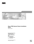
The Catalyst 6000 family consists of the 6-slot Catalyst 6006 switch and the 9-slot Catalyst 6009 switch.
The Catalyst 6500 series consists of the 6-slot Catalyst 6506 switch, the 9-slot Catalyst 6509 switch, the
9-slot Catalyst 6509NEB switch (shown in Figure 1-1), and the 13-slot 6513 switch.
These high-performance, modular, frame-based switches support high-density Fast Ethernet and Gigabit
Ethernet in both campus-backbone and server-aggregation environments. The Catalyst 6006 and the
Catalyst 6009 switches have a 32-Gbps switching capacity, while the Catalyst 6506, the Catalyst 6509,
and the Catalyst 6509-NEB switches can support a backplane architecture that scales from 32 Gbps to
256 Gbps.
All platforms share the same supervisor engines, switching modules, and software, and support
redundant configurations of supervisor engines, power supplies, and port interfaces.
For additional information about the Catalyst 6000 family switches, refer to the Catalyst 6000 Family
Installation Guide. For a complete list of Catalyst 6000 family documentation, see the “Related
Documentation” section on page xv.
Cisco 6500/7600 Series Manager User Guide
1-2
FAN
STATUS
AT
US
K
1
N
K
LI
N
K
LI
1
N
N
K
K
N
K
CONSOLE
LI
4
K
K
N
K
N
LI
4
N
LI
4
LI
4
CONSOLE
N
K
K
N
LI
3
E
MT
OL
T
EM
MG
US
R
NS
SE
ST
AT
ST
SY
CO
PW
RE
AT
US
1
LI
2
LI
LI
3
N
K
LI
N
2
N
K
LI
N
K
LI
N
K
K
K
N
K
N
LI
6
N
LI
6
LI
6
6
CONSOLE
PORT
MODE
LI
K
K
N
N
2
CONSOLE
PORT
MODE
2
LI
5
LI
K
K
N
K
N
LI
5
N
LI
5
LI
5
LI
7
N
K
K
K
N
K
N
LI
7
N
LI
7
LI
7
3
LI
3
LI
K
K
N
N
LI
8
K
K
N
K
N
LI
8
N
LI
8
LI
8
3
N
K
LI
N
K
LI
9
N
K
K
K
N
K
N
LI
9
N
LI
9
LI
9
K
4
4
LI
K
K
N
N
LI
LI
11
PCMCIA
N
K
K
N
K
N
LI
11
N
LI
11
LI
11
PCMCIA
LI
10
K
K
N
K
N
LI
10
N
LI
10
LI
10
4
N
K
LI
N
K
LI
13
EJECT
K
K
K
K
N
K
N
LI
13
N
LI
13
LI
13
EJECT
N
K
K
N
LI
12
LI
12
N
K
LI
N
N
5
N
K
LI
5
N
K
LI
LI
14
K
K
N
K
N
LI
14
N
LI
14
LI
14
5
N
K
LI
N
K
LI
15
K
K
K
N
K
N
LI
15
N
LI
15
LI
15
N
N
K
K
K
N
K
N
LI
16
N
LI
16
LI
16
LI
16
Supervisor
engine
12
LI
12
LI
K
6
N
K
LI
N
K
Load
K
LI
18
K
K
N
K
N
LI
18
N
LI
18
LI
18
N
Load
Switch
K
N
6
Switch
1%
100%
1%
100%
N
LI
6
LI
17
K
K
N
K
N
LI
17
N
LI
17
LI
17
LI
19
N
K
K
K
N
K
N
LI
19
N
LI
19
LI
19
K
LI
K
N
7
N
K
LI
N
N
K
LI
21
K
K
K
N
K
N
LI
21
N
LI
21
LI
21
K
LI
7
K
LIN
PORT 1
N
7
LIN
PORT 1
LI
20
K
K
N
K
N
LI
20
N
LI
20
LI
20
N
K
K
K
N
K
N
LI
22
N
LI
22
LI
LI
22
N
8
LI
K
K
K
N
K
N
LI
23
N
LI
23
LI
23
LI
23
N
K
LIN
8
K
LI
N
N
K
PORT 2
K
LI
8
N
24
K
K
K
N
LI
K
N
LI
24
N
LI
24
LI
24
K
LIN
PORT 2
Redundant
supervisor
engine
22
OUTPUT
FAIL
FAN
OK
INPUT
OK
WS-X6K-SUP2-2GE
SUPERVISOR2
ST
US
N
LI
3
3
E
MT
OL
T
EM
MG
US
R
NS
SE
ST
AT
ST
SY
CO
PW
RE
WS-X6K-SUP2-2GE
ST
SUPERVISOR2
WS-X6408
AT
LI
1
K
K
N
K
N
LI
2
N
LI
2
LI
2
8 PORT GIGABIT ETHERNET
WS-X6408
ST
US
AT
K
8 PORT GIGABIT ETHERNET
WS-X6408
ST
K
K
N
K
N
LI
1
N
LI
1
LI
1
OUTPUT
FAIL
FAN
OK
INPUT
OK
8 PORT GIGABIT ETHERNET
WS-X6224
US
US
AT
AT
ST
24 PORT 100FX
WS-X6224
ST
24 PORT 100FX
WS-X6224
US
AT
ST
24 PORT 100FX
WS-X6224
24 PORT 100FX
Switching
modules
Fan
assembly
Catalyst 6509-NEB Switch
Figure 1-1
30695
Product Overview
Chapter 1
Catalyst 6000 Family Overview
Slots 1-9
(right to left)
o
o
Power supply 1
Power supply 2
(redundant)
ESD ground strap
connection
Cisco 6500/7600 Series Manager User Guide
1-3
Chapter 1
Product Overview
Cisco 7600 Series Overview
Cisco 7600 Series Overview
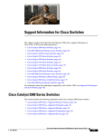
The Cisco 7600 series Internet Routers consist of the 3-slot 7603, the 6-slot 7606, and the vertical 9-slot
7609 (shown in Figure 1-2).
The Cisco 7600 series Internet Routers deliver optical LAN, WAN, and MAN networking with a focus
on line-rate delivery of high-touch IP services at the network edge. Service providers can “service
enable” their networks at optical speeds, enabling them to differentiate their service offerings for
competitive advantage.
The Cisco 7600 series Internet Routers support the following features:
•
30 Mpps forwarding processor and up to 512 MB DRAM for Internet routing
•
Up to two distributed Parallel Express Forwarding (PXF) IP services processors on each Optical
Services Module (OSM) for flexible IP service implementation
•
High-touch, line-rate IP services at 6 Mpps per slot:
– QoS
– Hierarchical traffic shaping
– Destination sensitive services (accounting, billing, and QoS)
•
The ability to monitor service levels delivered to customers under service level agreements (SLAs)
•
Wide range of WAN and MAN interfaces providing DS0 through OC-48 (using the FlexWAN
module)
•
Compatibility with the Catalyst 6000 family LAN interfaces offering 10 Mbps Ethernet to 1 Gbps
Cisco 6500/7600 Series Manager User Guide
1-4
FAN
STATUS
1
1
2
AT
SY
US
SY
US
1
2
LI
ST
ST
E
R
R
T
SE
MT
SE
MT
RE
MG
RE
MG
PW
OL
E
PW
OL
NS
NS
CO
EM
CO
EM
1
2
NK
LI 1
T
3
CONSOLE
CONSOLE
NK
LI 2
NK
LI 2
3
3
LI
NK
LI 2
NK
NK
4
4
NK
LI 4
SE
RE
T
K
T
LIN
T
R
IE
M
R
IE
M
AC
1
TI
RR
CA AR
AL
1
RR
CA AR
AL
R
IE
M
RR
CA AR
AL
SE
SE
RE
RE
T
SE
T
NK
LI IER
M
RE
SE
RR
CA AR
AL
RE
NK
LI IER
M
RR
CA AR
AL
NK
LI 4
NK
LI 4
NK
NK
4 LI
CONSOLE
PORT
MODE
NK
LI 3
NK
LI 3
3
4 LI
CONSOLE
PORT
MODE
3
4
3
NK
LI 3
NK
NK
LI
3
1
4
4
NK
LI 1
2 LI
1
1
NK
LI 1
NK
2 LI
2
LI
NK
TI
TI
2
1
TX
1
RT
RT
PO
PO
RX
RX
1
3
RT
3
PO
PCMCIA
TX
RX
TX
RX
RX
PCMCIA
VE
TX
VE
AC
AC
VE
RX
2
EJECT
TX
TI
TI
VE
VE
AC
AC
VE
5
5
RX
TX
R
IE
RR M
CA AR K
AL LIN
R
IE
M
R
IE
M
AC
RR
CA AR
AL
R
IE
M
TI
RR
CA AR
AL
EJECT
TX
4
RR
CA AR
AL
4
TX
RX
TX
RX
6
RX
6
PO
RX
7
2
TX
2
RT
RT
PO
PO
2
RX
RT
7
TX
TX
100%
AC
8
AC
VE
TI
TX
RX
RX
TX
Load
Load
VE
RX
TX
VE
TI
Switch
TI
AC
Switch
1%
100%
1%
R
IE
M
R
IE
RR M
CA AR
AL
RR
CA AR
AL
R
IE
M
RR
CA AR
AL
8
RX
PO
RX
K
PORT 1
LIN
K
TI
R
IE
RR M
CA AR
AL
AC
R
IE
RR M
CA AR K
AL LIN
R
IE
M
RR
CA AR
AL
TX
TX
LIN
PORT 1
3
TX
3
RT
RT
PO
PO
3
RX
RT
TI
TI
VE
RX
TX
VE
AC
AC
VE
TX
RX
TX
RX
RX
RX
RX
TX
TX
PORT 2
K
PORT 2
LIN
TX
OUTPUT
FAIL
FAN
OK
INPUT
OK
WS-X6K-SUP2-2GE
ST
SUPERVISOR2
AT
WS-X6K-SUP2-2GE
ST
SUPERVISOR2
OSM-40C12-POS-MM
US
AT
ST
OC12 POS MM
US
AT
ST
OSM-40C12-POS-MM
SWITCH FABRIC MDL
WS-C6500-SFM
OC12 POS MM
WS-C6500-SFM
US
US
AC
TIV
E
AC
TIV
E
SE
LE
CT
NE
XT
SE
LE
CT
NE
XT
OUTPUT
FAIL
FAN
OK
INPUT
OK
Supervisor
engine
Redundant
supervisor
engine
Switch
Fabric
Module
Redundant
Switch
Fabric
Module
ST
AT
US
ST
AT
US
SWITCH FABRIC MDL
AT
AT
2
OSM-40C12-POS-MM
US
AT
ST
OC12 POS MM
OSM-8OC3-POS MM
ST
8 PORT OC3 POS MM
ST
OSM-8OC3-POS MM
8 PORT OC3 POS MM
OSMs
Fan
assembly
Cisco 7609 Internet Router
Figure 1-2
55746
Product Overview
Chapter 1
Cisco 7600 Series Overview
Slots 1-9
(right to left)
o
o
Power supply 1
Power supply 2
(redundant)
ESD ground strap
connection
For additional information about the Cisco 7600 series Internet Routers, refer to the Cisco 7603 and
7606 Internet Router Installation Guide and Cisco 7609 Internet Router Installation Guide. For a
complete list of Cisco 7600 series Internet Router documentation, see the “Related Documentation”
section on page xv.
Cisco 6500/7600 Series Manager User Guide
1-5
Chapter 1
Product Overview
Supported Hardware
Supported Hardware
Table 1-1 lists the hardware that is supported by C65/76M, release 2.1:
Table 1-1
Supported Hardware
Platform
Part Number
Description
Catalyst 6000 family
chassis
WS-C6006
6-slot Catalyst 6000 series chassis
WS-C6009
9-slot Catalyst 6000 series chassis
WS-C6506
6-slot Catalyst 6500 series chassis
WS-C6509
9-slot Catalyst 6500 series chassis
WS-C6509-NEB
Vertical 9-slot Catalyst 6500 series chassis
WS-C6513
13-slot Catalyst 6500 series chassis
Cisco 7600 series chassis CISCO7603
3-slot Cisco 7600 series chassis
CISCO7606
6-slot Cisco 7600 series chassis
OSR-7609
Vertical 9-slot Cisco 7600 series chassis
WS-CAC-1000W
1000W AC power supply
WS-CAC-1300W
1300W AC power supply
WS-CAC-2500W
2500W AC power supply
WS-CAC-4000W
4000W AC power supply
WS-CDC-1300W
1300W DC power supply
WS-CDC-2500W
2500W DC power supply
PWR-950-AC
950W AC power supply
PWR-950-DC
950W DC power supply
PWR-1900-AC/6
1900W AC power supply
PWR-1900-DC
1900W DC power supply
Catalyst 6000 family
power supplies
Cisco 7600 series power
supplies
Cisco 6500/7600 Series Manager User Guide
1-6
Chapter 1
Product Overview
Supported Hardware
Table 1-1
Supported Hardware (continued)
Platform
Part Number
Description
Catalyst 6000 family
modules
WS-X6K-SUP1A-MSFC
Supervisor Engine 1A with MSFC
WS-X6K-S1A-MSFC2
Supervisor Engine 1A with MSFC2
WS-X6K-S2-MSFC2
Supervisor Engine 2 with MSFC2
WS-X6K-S2U-MSFC2
Supervisor Engine 2 with 256 MB DRAM
and MSFC2
WS-X6066-SLB-APC
Content Switching Module
WS-X6182-2PA
FlexWAN Module
WS-X6224-100FX-MT
24-port 100FX, MT-RJ
WS-X6324-100FX-MM
24-port 100FX, MT-RJ, multimode fiber,
128K per port packet buffers
WS-X6324-100FX-SM
24-port 100FX, MT-RJ, single-mode fiber,
128K per port packet buffers
WS-X6248-RJ-45
48-port 10/100TX, RJ-45
WS-X6248-TEL
48-port 10/100TX, RJ-21
WS-X6248A-TEL
48-port 10/100TX, RJ-21, 128K per port
packet buffers
WS-X6348-RJ-45
48-port 10/100TX, RJ-45, 128K per port
packet buffers
WS-X6348-RJ45V
48-port 10/100TX, RJ-45, 128K per port
packet buffers with inline power
WS-X6348-RJ-21
48-port 10/100, RJ-21, upgradable to voice
WS-X6348-RJ-21V
48-port 10/100, RJ-21, inline power
WS-X6524-100FX-MM
Fabric-enabled 100FX Fast Ethernet
Module, multimode fiber, MT-RJ
WS-X6548-RJ-21
Fabric-enabled 10/100 Fast Ethernet
Modules, RJ-21
WS-X6548-RJ-45
Fabric-enabled 10/100 Fast Ethernet
Modules, RJ-45
Cisco 6500/7600 Series Manager User Guide
1-7
Chapter 1
Product Overview
Supported Hardware
Table 1-1
Supported Hardware (continued)
Platform
Part Number
Description
Catalyst 6000 family
modules (continued)
WS-X6408-GBIC
8-port Gigabit Ethernet
WS-X6408A-GBIC
8-port Gigabit Ethernet with enhanced QoS
WS-X6416-GBIC
16-port Gigabit Ethernet
WS-X6416-GE-MT
16-port Gigabit Ethernet, MT-RJ
WS-X6516-GBIC
16-port Gigabit Ethernet, single
fabric-enabled connection
WS-X6816-GBIC
16-port Gigabit Ethernet, dual
fabric-enabled with Distributed
Forwarding, (Req GBICs)
WS-X6316-GE-TX
16-port Gigabit Ethernet, RJ-45
WS-X6501-10GEX4
One-port 10GBASE-EX4 Metro Extended
Reach 10 Gigabit Ethernet Module
(single-mode fiber)
WS-X6502-10GE
1-port 10GBASE-LR Serial 130nm Long
Haul 10 Gigabit Ethernet module
(WS-G6488 installed)
WS-X6516-GE-TX
16-port Gigabit Ethernet, RJ-45, x-bar
WS-X6066-SLB-APC
Server Load Balancing Module
WS-C6500-SFM
Switch Fabric Module
WS-C6500-SFM2
Switch Fabric Module, version 2
OSM-4GE-WAN-GBIC
4-port Gigabit Ethernet Optical Services
Module, GBIC
OSM-4OC12-POS-MM
4-port OC-12/STM-4 SONET/SDH OSM,
MM, with 4 ports of Gigabit Ethernet
OSM-4OC12-POS-SI
4-port OC-12/STM-4 SONET/SDH OSM,
SM-IR, with 4 ports of Gigabit Ethernet
OSM-4OC12-POS-SL
4-port OC-12/STM-4 SONET/SDH OSM,
SM-LR, with 4 ports of Gigabit Ethernet
OSM-1OC48-POS-SS
1-port OC-48/STM-16 SONET/SDH OSM,
SM-SR, with 4 ports of Gigabit Ethernet
OSM-1OC48-POS-SI
1-port OC-48/STM-16 SONET/SDH OSM,
SM-IR, with 4 ports of Gigabit Ethernet
Cisco 6500/7600 Series Manager User Guide
1-8
Chapter 1
Product Overview
Supported Hardware
Table 1-1
Supported Hardware (continued)
Platform
Part Number
Description
Cisco 7600 Optical
Services Modules
(continued)
OSM-1OC48-POS-SL
1-port OC-48/STM-16 SONET/SDH OSM,
SM-LR, with 4 ports of Gigabit Ethernet
OSM-16OC3-POS-MM
16-port OC-3/STM-1 SONET/SDH OSM,
MM, with 4 ports of Gigabit Ethernet
OSM-16OC3-POS-SI
16-port OC-3/STM-1 SONET/SDH OSM,
SM-IR, with 4 ports of Gigabit Ethernet
OSM-16OC3-POS-SL
16-port OC-3/STM-1 SONET/SDH OSM,
SM-LR, with 4 ports of Gigabit Ethernet
OSM-2OC12-POS-MM
2-port OC-12/STM-4 SONET/SDH OSM,
MM, with 4 ports of Gigabit Ethernet
OSM-2OC12-POS-SI
2-port OC-12/STM-4 SONET/SDH OSM,
SM-IR, with 4 ports of Gigabit Ethernet
OSM-2OC12-POS-SL
2-port OC-12/STM-4 SONET/SDH OSM,
SM-LR, with 4 ports of Gigabit Ethernet
OSM-8OC3-POS-MM
8-port OC-3/STM-1 SONET/SDH OSM,
MM, with 4 ports of Gigabit Ethernet
OSM-8OC3-POS-SI
8-port OC-3/STM-1 SONET/SDH OSM,
SM-IR, with 4 ports of Gigabit Ethernet
OSM-8OC3-POS-SL
8-port OC-3/STM-1 SONET/SDH OSM,
SM-LR, with 4 ports of Gigabit Ethernet
OSM-1CHOC48/T3-SS
1-port channelized OC48 OSM, SM-SR,
with 4 Gigabit Ethernet
OSM-1CHOC48/T3-SI
1-port channelized OC48 OSM, SM-IR,
with 4 Gigabit Ethernet
OSM-2CHOC48/T3-SS
2-port channelized OC48 OSM, SM-SR,
with 4 ports of Gigabit Ethernet
OSM-2CHOC48/T3-SI
2-port channelized OC-48 OSM, SM-IR,
with 4 ports of Gigabit Ethernet
OSM-4CHOC12/T3-MM
4-port channelized OC-12 OSM, MM,
with 4 ports of Gigabit Ethernet
OSM-4CHOC12/T3-SI
4-port channelized OC-12 OSM, SI,
with 4 ports of Gigabit Ethernet
OSM-8CHOC12/T3-MM
8-port channelized OC-12 OSM, MM,
with 4 ports of Gigabit Ethernet
OSM-8CHOC12/T3-SI
8-port channelized OC-12 OSM, SI,
with 4 ports of Gigabit Ethernet
Cisco 7600 Optical
Services Modules
(continued)
Cisco 6500/7600 Series Manager User Guide
1-9
Chapter 1
Product Overview
Supported Software
Supported Software
The Cisco 6500/7600 Series Manager, version 2.1, supports Native IOS Release 12.1(3a)E3 to
Release 12.1(11)E. It also supports Hybrid OS in the following combinations:
Note
•
Catalyst OS 6.3(3a) and IOS 12.1(8)E
•
Catalyst OS 7.1(2) and IOS 12.1(8)E
•
Catalyst OS 7.1(2) and IOS 12.1(11)E
The Cisco 6500/7600 Series Manager does not support Catalyst 6000 family switches or Cisco 7600
series Internet Routers running only Catalyst software (no Multilayer Switch Feature Card installed).
Cisco 6500/7600 Series Manager User Guide
1-10
C H A P T E R
2
Basic Concepts
This chapter describes basic concepts and terminology used in this guide, and consists of these sections:
•
Cisco EMF and Cisco 6500/7600 Series Manager Software, page 2-1
•
C65/76M Objects and Interfaces, page 2-3
•
Containment Views, page 2-7
•
C65/76M Object States, page 2-8
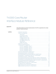
Cisco EMF and Cisco 6500/7600 Series Manager Software
The C65/76M is the carrier-class element manager for the Catalyst 6000 family switches and Cisco 7600
series Internet Routers, which “plugs into” CEMF. The C65/76M software adds additional windows and
a back-end controller process that communicates with the hardware elements (using CEMF), as shown
in the following figure.
Cisco 6500/7600 Series Manager User Guide
2-1
Chapter 2
Basic Concepts
Cisco EMF and Cisco 6500/7600 Series Manager Software
Figure 2-1
CEMF and C65/76M Processes
Cisco EM controller
Element Manager
Windows
C65/76M
controller
Cisco EM
Database
Cisco C65/76M
Database
CEMF
Catalyst 6500
73603
Management
Network
Element Management
An Element Manager is an application that is responsible for providing fault, configuration, accounting,
performance and security (FCAPS) management for a particular type of Network Element or family of
Network Elements. The C65/76M software primarily provides fault and performance information. The
configuration capabilities are limited, and the accounting information is used for inventory purposes. No
security information is provided by the C65/76M.
Cisco 6500/7600 Series Manager User Guide
2-2
Chapter 2
Basic Concepts
C65/76M Objects and Interfaces
C65/76M Objects and Interfaces
The C65/76M software provides three types of objects:
•
Physical—Represents actual components and devices such as the chassis (hardware frame), fans,
power supplies, modules, and ports.
•
Logical—Represents the nontangible features, such as VLAN configurations, EtherChannels, and
routing protocols.
•
Network element—Represents the entire Catalyst 6000 family multilayer switch or Cisco 7600
series Internet Router managed through a single SNMP agent and IOS command-line interface.
Physical Objects
The C65/76M software models the following physical components:
•
Chassis—The hardware frame of the Catalyst 6000 family switch or the Cisco 7600 series Internet
Router
•
Power supplies—The source of power for the Catalyst 6000 family switch or the Cisco 7600 series
Internet Router
•
Supervisor Engine modules—Contain the route and switch processors
•
Ethernet interfaces—Ports on Ethernet modules and supervisor engine modules
•
Ethernet modules—Represent Ethernet, Fast Ethernet, and Gigabit Ethernet modules
•
Switch Fabric Modules—Provide connection to the crossbar switching fabric
•
FlexWAN modules —Supports up to two port adapters that provide WAN and MAN connections
•
Port adapters—The port adapters plug into the FlexWAN module to provide WAN and MAN
connections
•
OSM GeWAN modules/interfaces—Modules and associated ports that provide 4 Gigabit Ethernet
WAN connections
•
OSM PoS modules/interfaces—Modules and associated ports that provide Packet-over-SONET
(PoS) connection support
•
OSM Channelized SONET modules/interfaces—Modules and associated ports that provide
SONET-based channelizing of interface bandwidth, including both PoS and serial subinterfaces
•
Content Switching Modules—Defines a virtual server that represents a cluster of real servers
Cisco 6500/7600 Series Manager User Guide
2-3
Chapter 2
Basic Concepts
C65/76M Objects and Interfaces
These C65/76M objects have the following hierarchical organization:
•
Chassis
– Power supplies
– Supervisor engine modules:
Ethernet interfaces
– Ethernet modules:
Ethernet interfaces
– Switch Fabric Modules
– FlexWAN Modules
Port adapters:
ATM port adapters
ATM SONET interfaces
ATM E3 interfaces
ATM T3 interfaces
– OSM GeWAN Modules
OSM GeWAN interfaces
– OSM PoS Modules
Ethernet interfaces
OSM PoS interfaces
– OSM Channelized SONET Modules
Ethernet interfaces
OSM ChSONET interfaces
OSM Serial Subinterfaces
OSM PoS Subinterfaces
– Content Switching Modules
Logical Objects
The C65/76M models the following logical components:
•
Software—Represents the IOS image and configuration file on the Catalyst 6000 family switch or
Cisco 7600 series Internet Router
•
EtherChannels—Creates, deletes, and modifies EtherChannels on the Catalyst 6000 family switch
or Cisco 7600 series Internet Router
•
VLAN—Lists, creates, and deletes VLAN interfaces on the Catalyst 6000 family switch or Cisco
7600 series Internet Router
•
Loopback—Used to isolate the fault on an end-to-end circuit
•
Syslog—Represents the standard syslog messaging protocol on the Catalyst 6000 family switch or
Cisco 7600 series Internet Router
•
ACL—Represent access control lists, both standard and extended, named and numbered
Cisco 6500/7600 Series Manager User Guide
2-4
Chapter 2
Basic Concepts
C65/76M Objects and Interfaces
•
NDE—NetFlow Data Export (NDE) makes traffic statistics available for analysis by an external
data collector
•
QoS—Enables and manages the global quality of service (QoS) engine.
•
QoS policy map—Describes the traffic filters applied to enforce QoS parameters on ingress traffic
received on an interface or VLAN.
•
EIGRP—Creates, modifies, and deletes Enhanced Interior Gateway Routing Protocol (EIGRP)
instances on the Catalyst 6000 family switch or Cisco 7600 series Internet Router
•
BGP—Creates and modifies Border Gateway Protocol (BGP) routing protocol
•
OSPF—Displays the Open Shortest Path First (OSPF) routing protocol information for the Catalyst
6000 family switch or Cisco 7600 series Internet Router
•
VTP—VLAN Trunking Protocol
•
STP—Spanning Tree Protocol
•
IS-IS—Creates, modifies, and deletes intermediate system-to-intermediate system (IS-IS) routing
processes on the Catalyst 6000 family switch or Cisco 7600 series Internet Router
These components have the following hierarchical organization:
•
Software
– EtherChannels
– Syslog
– EIGRP
– BGP
– OSPF
– VTP
– VLAN
– STP
– IS-IS
– ACL
– NDE
– Loopback
– QoS
QoS policy map
Cisco 6500/7600 Series Manager User Guide
2-5
Chapter 2
Basic Concepts
C65/76M Objects and Interfaces
Network Element Object
The Network Element object is a logical container representing the entire Catalyst 6000 family
multilayer switch or Cisco 7600 series Internet Router managed through the supervisor and/or MSFC
SNMP agents and Catalyst OS/IOS command-line interface. This class acts as a container for the
physical and logical components of the device. The entire hierarchical structure of the C65/76M
components is as follows:
Network Element
Chassis
Power Supplies
Supervisor Modules
Ethernet Interfaces
Ethernet Modules
Ethernet Interfaces
Switch Fabric Modules
FlexWAN Modules
Port Adapter
ATM Port Adapter
ATM SONET Interfaces
ATM E3 Interfaces
ATM T3 Interfaces
OSM GeWAN Modules
OSM GeWAN Interfaces
OSM POS Modules
Ethernet Interfaces
OSM POS Interfaces
OSM Channelized SONET Modules
Ethernet Interfaces
OSM Channelized SONET Interfaces
OSM Serial Sub-interfaces
OSM POS Sub-interfaces
Content Switching Modules
Software
EtherChannels
Syslog
EIGRP
BGP
OSPF
VTP
VLAN
STP
IS-IS
ACL
NDE
Loopback
QoS
QoS Policy Map
Cisco 6500/7600 Series Manager User Guide
2-6
Chapter 2
Basic Concepts
Containment Views
Containment Views
The CEMF Map Viewer application uses a concept called containment views to allow logical grouping
of monitored objects. Objects being managed by CEMF must be added to one or more containment
views. Objects are organized into different views and can exist in multiple views simultaneously by
reference. Objects can be in one or more containment views. Figure 2-2 shows the default network
containment view and default physical containment view in the Map Viewer application.
Figure 2-2
Default Network Containment View
When installed, the C65/76M does not modify the visible containment views and all managed objects
will appear in the Physical tree. Note that previous versions of the EMS added three other containment
views (Catalyst6000Manager, Catalyst6500Manager and Cisco7600Manager) - if these views are
present the version 2.0 release of the Manager application is still installed. See the Cisco 6500/7600
Manager Installation Guide for instruction on removing the previous version of the Manager.
Network View
The network view is a standard feature in CEMF. This view is used by the CEMF Auto Discovery feature
to determine which devices have already been added to the system so that Auto Discovery does not try
to discover the same device multiple times. This view displays all IP devices under their parent network
(that is, it groups monitored objects in a network layout). This view provides a logical view of the
network structure. For example, devices on the same subnet would be grouped together. Refer to the
Cisco Element Management Framework User Guide for more information.
Cisco 6500/7600 Series Manager User Guide
2-7
Chapter 2
Basic Concepts
C65/76M Object States
Physical View
The physical view is a standard feature in CEMF. Objects in the physical view are ordered according to
their relative geographical or physical location. The relationships defined in this view are physical
containment relationships. For example, monitored objects physically located in the same room or
location may be grouped together under the same site. Refer to the Cisco Element Management
Framework User Guide for more information.
C65/76M Object States
All C65/76M objects have states associated with them. Each state corresponds to a specific task that is
performed in that state. For example, in the performance state, attributes are being polled at a predefined
rate. State changes can be triggered by actions, or selected SNMP traps from the device. The state of an
object can change frequently, depending upon what actions are being performed on the object. All
objects in CEMF have a state assigned to them, which appears at the bottom left corner of each dialog
box for a selected object. The following are the two most common object states:
•
Normal
•
Decommissioned
Some states are inherited by an object’s children. For example, if a chassis is decommissioned, all
subchassis objects are also decommissioned. If performance logging is enabled on a module,
performance logging is enabled on all ports of that module.
Decommissioned State
The decommissioned state indicates that an object is not being managed. When an object is initially
deployed, it is normally placed into a decommissioned state. The following actions occur on a
decommissioned object:
•
Active management stops
•
All subobjects also are decommissioned
Decommission buttons can be found within certain windows, dependent upon the type of object selected.
When an object is decommissioned, the children of that object also change their state to
decommissioned. For example, if a module is decommissioned, all interfaces and connections on that
module are decommissioned.
Objects can be put into the decommissioned state from any other state.
Discovery State
The discovery state is a temporary state that is assigned to certain objects during subchassis discovery.
This state applies to the Network Element, Chassis and Software objects. It is used to determine the
physical and logical components on a switch. If successful, an automatic state transition to normal is
made. If communication is lost, the object transitions to the discovery lostcomms state. If physical
components are detected that do not match the expected types, the objects are transitioned to the
mismatched state.
Cisco 6500/7600 Series Manager User Guide
2-8
Chapter 2
Basic Concepts
C65/76M Object States
Normal State
The normal state is applicable to all objects, and represents a situation in which an object is regarded as
being actively monitored. When an object enters the normal state, CEMF performs heartbeat polling on
the object every five minutes to check for connectivity or changes to the object.
Lostcomms State
This state applies only to the Network Element object. If communication to the Network Element object
is lost, it moves into the lostcomms state. Heartbeat polling polls an object every five minutes to verify
its existence and current state. Heartbeat polling continues, until the object responds positively to a
heartbeat request. When the object can be contacted again, it responds positively to heartbeat requests,
and then moves back into the normal state.
Normal Lostcomms State
This state applies all objects except the Network Element object. This state indicates that communication
has been lost to an object that was formerly in the normal state. Two transistions can be made out of this
state:
•
If communication is restored, the object transitions back to the normal state.
•
While this object is still in the normal lostcomms state, if the object is stimulated to activate
performance logging, then the transistion is immediately to the perflostcomms state.
Performance State
This state applies all physical objects that support Performance Logging. When you enable performance
logging on an object in the normal state, the object is moved into the performance state. Specific
performance data is collected on the object and can be viewed in the Performance Manager. You can
enable performance logging on a global scale or on an individual interface basis. Enabling global
performance logging puts all subchassis objects into the performance state.
Performance logging occurs at the specified interval. When you initially enable performance logging or
global performance logging on an object, it takes a period of time up to the length of the interval for the
data to be collected and become visible in C65/76M performance menus.
Heartbeat polling is performed on an object in the performance state. If the object moves into the
lostcomms state, it is returned to the performance state when the error is corrected. For example, if a
module is in the performance state and it fails, it moves into the lostcomms state. When heartbeat polling
finds the module is back up, it restores the module to the performance state.
There are three transitions out of the performance state:
•
If communication to the object is lost while the object is in the performance state, the state transition
is into the perflostcomms state.
•
To turn off the object’s performance logging, you can send the object the normal stimulus. The
transistion is to the normal state.
•
If heartbeat polling determines that connectivity is lost or changes have been made to the object, the
transition is to the discovery state. Once dicovery is completed successfully, the object transitions
back to the performance state.
Cisco 6500/7600 Series Manager User Guide
2-9
Chapter 2
Basic Concepts
C65/76M Object States
Perflostcomms State
This state applies all physical objects that support Performance Logging. This state indicates that
communication has been lost to an object that was formerly in the performance state. Two transistions
can be made out of this state:
•
If communication is restored, the object transitions back to the performance state.
•
While this object is still in the perflostcomms state, if the object is stimulated to deactivate
performance logging, then the transistion is immediately to the normal lostcomms state.
If communication to an object is lost, it moves into the lostcomms state. In this state, performance
polling (if activated) is stopped; however, heartbeat polling continues, until the object responds
positively to a heartbeat request. Heartbeat polling polls an object every five minutes to verify its
existence and current state. When the object can be contacted again, it responds positively to heartbeat
requests, and then moves back into the previously held state.
Discovery Lostcomms State
The discovery lostcomms state applies to Network Element, Software and Chassis objects. This state is
similar to the lostcomms state, except that it only occurs during the discovery process. When
connectivity is established with the corresponding object in the device, the discovery is resumed and the
object moves out of the discovery lostcomms state.
Mismatched State
The mismatched state occurs when a mismatch is found between the type of hardware discovered and
what is predeployed in CEMF. For example, if a 48-port 10/100TX, RJ-45 module is expected, the
module is predeployed in CEMF to prepare for that type of module. However, when the module becomes
available and is placed into the chassis, it is not a 48-port 10/100TX, RJ-45 module, but an 8-port Gigabit
Ethernet module. After the C65/76M detects the new module, it finds a mismatch. The module gets
placed into the mismatched state and an alarm is raised against the module.
To correct a mismatch problem, the source of the problem must be assessed. If the operator was at fault
and predeployed an incorrect module, the operator should delete the predeployed module and deploy the
correct module. If the engineer is at fault and inserted the wrong type of module into the chassis, then
the module should be removed and replaced.
The mismatched state applies to the following objects:
•
Network element
•
All modules
•
Port Adapters
•
Channelized SONET subinterfaces
For the Network Element object, the mismatched state indicates that there is a major difference between
the CEMF information and the actual Catalyst 6000 family switch or a Cisco 7600 series Internet
Router. This mismatch can be in the major switch series (e.g. 6000, 6500 or 7600), the specific model
of the switch (e.g. 6506, 6509 or 6513) or the type of software installation on the switch (Catalyst OS,
Hybrid OS or Native IOS).
Cisco 6500/7600 Series Manager User Guide
2-10
C H A P T E R
3
Getting Started
This chapter describes the typical tasks to be completed when first using the Cisco 6500/7600 Series
Manager, and consists of the following sections:
•
Preparing to Use the C65/76M Software, page 3-1
•
Using Cisco EMF, page 3-2
•
Deploying C65/76M Objects, page 3-7
•
Launching Object Management Dialogs, page 3-10
Preparing to Use the C65/76M Software
The following table outlines the general steps involved in using the C65/76M software.
Table 3-1
Using C65/76M
Steps
Description
Step 1
Install and start Cisco EMF.
Refer to the Cisco Element Management
Framework Installation and Administration
Guide for more information on how to
install and start Cisco EMF.
Step 2
Install the C65/76M software.
Refer to the Cisco 6500/7600 Manager
Installation Guide for more information.
Step 3
Set up the Catalyst 6000 family
switch or the Cisco 7600 series
Internet Router.
You must configure the Catalyst 6000
family switch or Cisco 7600 series Internet
Router before it can be properly managed by
Cisco EMF. Refer to the “Hardware
Configuration Requirements” section in the
Cisco 6500/7600 Manager Installation
Guide for more information.
Step 4
Start a Cisco EMF session.
Starting a Cisco EMF user session provides
access to all C65/76M functionality.
Step 5
Deploy objects.
Refer to the “Deploying C65/76M Objects”
section of this chapter for more information.
Cisco 6500/7600 Series Manager User Guide
3-1
Chapter 3
Getting Started
Using Cisco EMF
Using Cisco EMF
The Cisco EMF Launchpad application is the main starting point for using Cisco EMF. The Launchpad
can be accessed by starting a Cisco EMF user session.
Note
Before you can start a Cisco EMF user session, Cisco EMF has to be running. If a message is displayed
indicating that Cisco EMF is not running, contact the system administrator.
To start a Cisco EMF user session, do the following:
Step 1
From the command line on the terminal window, type the following:
Cisco EMF_ROOT/bin/Cisco EMF session
Note
Replace Cisco EMF_ROOT with the root directory in which Cisco EMF is installed (for example,
/opt/Cisco EMF).
The login window (Figure 3-1) appears.
Figure 3-1
Login Window
Cisco 6500/7600 Series Manager User Guide
3-2
Chapter 3
Getting Started
Using Cisco EMF
Step 2
Enter your user name and password, then click Ok to proceed.
When an invalid user name or password is entered, an error is displayed. Click Ok and then enter
a valid user name and password. Three attempts to enter a valid user name and password are
allowed. If a valid user name and password are not entered within three attempts, the login
window closes.
Note
When a valid user name and the password are entered, the session starts and the Cisco EMF Launchpad
window appears (see Figure 3-2).
Cisco Element Management Framework Launchpad Window
The icons displayed in the Launchpad window (see Figure 3-2) represent applications that are provided
by Cisco Element Management Framework (Cisco EMF). The icons and applications are:
Viewer
•
Groups
•
Access
•
Events
•
Discovery
•
Notify
•
Thresholds
•
Event Grps
For more information, refer to the Cisco Element Management Framework User Guide.
Cisco 6500/7600 Series Manager User Guide
3-3
Chapter 3
Getting Started
Using Cisco EMF
Figure 3-2
Cisco EMF Launchpad
Viewer
The Viewer icon provides access to the Cisco EMF Map Viewer application, which provides complete
flexibility in viewing, building, and monitoring a network using graphical representations of Network
Elements. The Map Viewer application is the primary access point for C65/76M management functions.
Groups
The Groups icon provides access to the Cisco EMF Object Group Manager application, which provides
the opportunity to organize Network Elements into object groups. The Object Group Manager allows the
creation, deletion, and modification of object groups. Object groups can be any combination of objects
derived from the Cisco EMF managed object class. Objects can be added manually or on the basis of
query criteria.
Access
The Access icon provides access to the Cisco EMF User Access Control application, which is a
component of Carrier Class Security and provides system administrators the opportunity to control
which features of their system can be accessed by various levels of personnel. This is important for
security and efficient and effective network management.
Cisco 6500/7600 Series Manager User Guide
3-4
Chapter 3
Getting Started
Using Cisco EMF
Events
The Events icon provides access to the Event Browser application. In Cisco EMF, when a condition
(fault) occurs on a managed object in the network, the system is notified immediately. This notification
is shown as an event and can be viewed with the Event Browser. One of the most important aspects of
network service management is the ability to identify events on the system and to take action to resolve
them quickly and efficiently. For example, there may be a power supply fault in a chassis which would
require an engineer to be sent out to rectify the fault. This fault is critical to the running of the network
and would need prompt attention.
Discovery
The Discovery icon provides access to the Cisco EMF Auto Discovery application, which examines the
network for IP and SNMP devices and creates a managed object for each new device discovered. Auto
Discovery can be opened from the Cisco EMF Launchpad window or from a pop-up menu available on
a selected object.
Notify
The Notify icon provides access to the Notification feature. An important aspect of a monitoring system
which captures and reacts to events on the network is when and how a network operator is informed of
these events. The Cisco EMF Event Manager uses notifications for providing this information. For
example, when the temperature of a module rises 10 degrees above normal, an e-mail might be sent to
the network operator warning of a potential problem and a minor event might be generated if the
temperature does not fall to within 10 degrees of normal within twenty minutes.
Notification profiles are collections of notifications. Each notification profile has a name and description
and can be accessed by all Event Manager users. Each profile includes a list of notifications, and is run
following a trigger, which might be an event entering an event group, or a threshold breach in a
thresholding regime. For example, when the first event is received by an event group, a notification
profile may be triggered that causes a sound to occur, which alerts the operator. As well as audible alerts,
a notification can be set up to display on screen, or to trigger an external notification, such as an e-mail.
Thresholds
The Thresholds icon provides access to the Thresholding Regime feature. A Thresholding Regime is a
set of threshold conditions for specified object attributes which, when breached, causes one or more
notification profiles to be run. The Thresholding Regime defines which attributes should be polled and
on what period, and defines the thresholding conditions. The Thresholding Regime specifies object
groups that contain the objects whose attributes will be polled.
Cisco 6500/7600 Series Manager User Guide
3-5
Chapter 3
Getting Started
Using Cisco EMF
Event Grps
The Event Grps icon provides access to the Event Groups application, which is used to organize Network
Elements into event groups and to view the status of these groups as scoreboards. You can create, delete,
and modify event groups and scoreboards. Event groups are available to all users.
Event groups can be any combination of objects derived from the Cisco EMF-managed object class.
These groups are set up using queries, which can be configured to match given requirements. For
example, a network administrator could choose to monitor a particular device, specify a time period, and
choose to look at events that are warnings or critical. You define a query so that the event group only
includes the events that meet the specified criteria.
Quitting a Cisco EMF User Session
To quit a Cisco EMF user session, follow these steps:
Step 1
Step 2
In the Launchpad window, do one of the following:
•
Click the Quit icon from the toolbar.
•
From the File menu, choose Quit.
•
Press Ctrl-Q.
A window appears, asking, Do you wish to quit the Cisco EMF Manager System? Click Yes to quit the
session. All active applications are closed and the session terminates.
Cisco 6500/7600 Series Manager User Guide
3-6
Chapter 3
Getting Started
Deploying C65/76M Objects
Deploying C65/76M Objects
To manage a Catalyst 6000 family switch or Cisco 7600 series Internet Router using Cisco EMF, a
C65/76M object must be deployed within Cisco EMF and commissioned. This section describes how to
manually deploy the Network Element object in Cisco EMF. For a detailed description on other
deployment options, refer to Chapter 4, “Deploying the C65/76M.”
To manually deploy a Catalyst 6500 Network Element object, follow these steps:
Step 1
Launch the Cisco EMF Map Viewer application from the Cisco EMF Launchpad window.
Step 2
Choose Deployment/QuickStart Deploy Catalyst 6500 Manager from the pop-up menu. This pop-up
menu item is available from the Physical containment tree root or another container object within that
tree.
Step 3
Enter the details for the switch and click the Forward button (see following figure).
Figure 3-3
Object Parameters
Cisco 6500/7600 Series Manager User Guide
3-7
Chapter 3
Deploying C65/76M Objects
Table 3-2
Object Parameter Definitions
Property
Description
Catalyst 6500 Switch
Name
Name of the Network Element object that will be
displayed in the Map Viewer application.
Supervisor IP Address
IP address of the switch supervisor engine.
CatOS/IOS SNMP V1
Read Community
SNMP v1 read community used by the device.
This deployment mode assumes the same
communities for either switch operating system.
CatOS/IOS SNMP V1
Write Community
SNMP v1 write community used by the device.
This deployment mode assumes the same
communities for either switch operating system.
CatOS/IOS SNMP V2c
Read Community
SNMP v2c read community used by the device.
This deployment mode assumes the same
communities for either switch operating system.
CatOS/IOS SNMP V2c
Write Community
SNMP v2c write community used by the device.
This deployment mode assumes the same
communities for either switch operating system.
CatOS/IOS SNMP
Version
The version of the SNMP agent running on the
device. This is a drop-down menu containing:
SNMPv1
•
SNMPv2c
CatOS/IOS Username
The username used to allow the C65/76M to
access the Network Element device using a Telnet
connection. This deployment mode assumes the
same username for either switch operating system.
CatOS/IOS Password
The password used to allow the C65/76M to
access the Network Element using a Telnet
connection. The value entered in this text box will
not be in plain text. This deployment mode
assumes the same password for either switch
operating system.
OS Deploy Type
If the specific OS installation type for the switch
is known, it can be selected here. Leave the setting
as autoDetect to let the EMS determine the OS
deployment type.
Cisco 6500/7600 Series Manager User Guide
3-8
•
Getting Started
Chapter 3
Getting Started
Deploying C65/76M Objects
Figure 3-4
Step 4
Deployment Wizard—Summary
Click the Finish button to deploy the Network Element object.
This procedure deploys a decommissioned Catalyst 6500 Network Element object in Cisco EMF and
automatically commissions it.
Once the network element is commissioned and discovery is complete, the physical view will resemble
Figure 3-5.
Cisco 6500/7600 Series Manager User Guide
3-9
Chapter 3
Getting Started
Launching Object Management Dialogs
Figure 3-5
Note
View of Commissioned Object
If you have installed hardware that is not supported by C65/76M, the module image will contain a “?”
in the hardware view.
Launching Object Management Dialogs
After all the objects in the network element are in the normal state, dialog boxes can be opened to
perform management operations on the network element.
To launch the management dialog box of a C65/76M object, right click its parent object in the Map
Viewer application or the object itself in the containment view. Select the option to open the object’s
dialog box from the pop-up menu. Refer to the “C65/76M Objects and Interfaces” section on page 2-3
for descriptions of the object hierarchies.
For example, to open the EtherChannel Dialog, right-click on the Software object and choose Open
EtherChannel Dialog from the pop-up menu, as shown in Figure 3-6.
Cisco 6500/7600 Series Manager User Guide
3-10
Chapter 3
Getting Started
Launching Object Management Dialogs
Figure 3-6
Launching an Object Management Dialog Box
Chapter 5, “Physical Object Dialog Boxes,” and Chapter 6, “Logical Object Dialog Boxes,” describe
how to use the dialog boxes for the physical and logical objects, respectively.
Cisco 6500/7600 Series Manager User Guide
3-11
Chapter 3
Launching Object Management Dialogs
Cisco 6500/7600 Series Manager User Guide
3-12
Getting Started
C H A P T E R
4
Deploying the C65/76M
This chapter describes how to deploy the Cisco 6500/7600 Series Manager, and consists of these
sections:
•
Managing a Catalyst 6000 Family Switch or a Cisco 7600 Series Internet Router, page 4-1
•
Deployment and Commissioning Process, page 4-5
Managing a Catalyst 6000 Family Switch or a Cisco 7600 Series
Internet Router
Managing a Catalyst 6000 family switch or a Cisco 7600 series Internet Router using CEMF is a
two-step process:
1.
Deploy objects that need to be managed.
C65/76M objects can be discovered automatically or deployed manually.
2.
Commission the objects to allow CEMF to manage them.
Deploying Objects
The deployment process should be done after you install the C65/76M software for the first time, or after
you install new hardware. Deployment informs the C65/76M of the presence of supported hardware.
The C65/76M objects can be automatically discovered or manually deployed. Objects can also be
predeployed in CEMF before the actual installation of a Catalyst 6000 family switch or a Cisco 7600
series Internet Router in the field.
Predeployment is the process of reserving a space in CEMF for network equipment, which has not yet
been physically slotted into the system rack. When an object or device is predeployed, the physical
device or object is not present, but CEMF has been preconfigured to hold an object of similar type. As
a result, C65/76M module objects can be deployed and the C65/76M will not monitor their status. When
a module is then placed in the physical equipment, the new module will be automatically detected and
management of the module will be automatically started.
Cisco 6500/7600 Series Manager User Guide
4-1
Chapter 4
Deploying the C65/76M
Managing a Catalyst 6000 Family Switch or a Cisco 7600 Series Internet Router
C65/76M Object Hierarchy
A fully deployed C65/76M object in CEMF has the following object hierarchy:
Network Element
Chassis
Power Supplies
Supervisor Modules
Ethernet Interfaces
Ethernet Modules
Ethernet Interfaces
Switch Fabric Modules
FlexWAN Modules
Port Adapter
ATM Port Adapter
ATM SONET Interfaces
ATM E3 Interfaces
ATM T3 Interfaces
OSM GeWAN Modules
OSM GeWAN Interfaces
OSM PoS Modules
Ethernet Interfaces
OSM PoS Interfaces
OSM Channelized SONET Modules
Ethernet Interfaces
OSM Channelized SONET Interfaces
OSM Serial Sub-interfaces
OSM PoS Sub-interfaces
Content Switching Modules
Software
EtherChannels
Syslog
EIGRP
BGP
OSPF
VTP
VLAN
STP
IS-IS
ACL
NDE
Loopback
QoS
QoS Policy Map
The top-level Network Element object represents the entire switch including the physical and logical
components of the switch. The Chassis object, which is a child of the Network Element object,
represents all the physical components of the switch. For example, the chassis frame, power supplies,
modules, and ports are all represented under the Chassis object. The Software object, which is a peer of
the Chassis object, represents all the logical components of the switch. For example, VLAN
configurations, EtherChannels, and routing protocols are represented under the Software object.
Note
The software object and its children are available only under the Catalyst6000Manager,
Catalyst6500Manager, and Cisco7600Manager containment views.
Cisco 6500/7600 Series Manager User Guide
4-2
Chapter 4
Deploying the C65/76M
Managing a Catalyst 6000 Family Switch or a Cisco 7600 Series Internet Router
Commissioning Objects
Commissioning is the action required to notify CEMF to start actively monitoring the object. Only the
following C65/76M objects can be commissioned and decommissioned by the user:
•
Network Element
•
Supervisor Module
•
Ethernet Module
•
Switch Fabric Module
•
FlexWAN Module
•
Content Switching Module
•
Port Adapter
•
OSM Module
When applied to these objects, the commissioning process is propagated down to all the object’s
children. For example, if the Network Element object is commissioned, all the C65/76M objects are also
commissioned. If only a Supervisor Module object is commissioned, then its Ethernet Interface objects
are also commissioned.
When the Network Element object is commissioned, a subchassis discovery is started to determine the
contents of the switch. If objects on the switch are discovered that do not currently exist in CEMF, then
these objects are automatically created and populated. For example, an Ethernet module would be
automatically populated with the appropriate number of interfaces when it is discovered. If the object
already exists in CEMF, then a type match is made against the CEMF object and the one found during
discovery. If a mismatch is found, the object is placed into the Mismatched state and an error is
generated. If there is no mismatch, then the object is commissioned successfully and CEMF begins to
monitor it.
Figure 4-1 shows the CEMF Map Viewer application with the C65/76M software installed. When an
object is deployed in CEMF, the objects are automatically added to the Network, Physical, and the
appropriate Manager Views. In this example, the Network Element objects are called “may” and
“morar,” the Chassis objects are called “may-Chassis” and “morar-Chassis,” and the Software objects
are called “may-Software” and “morar-Software.”
Under the Network container, the Network Element objects are labelled by their IP addresses and added
to the group representing the subnet that they belong to (192.168.12.0). Under the Physical container,
the Network Element and Chassis objects are available.
Note
The Software objects are available only under the Catalyst6000Manager, Catalyst6500Manager, and
Cisco7600Manager containment views.
Cisco 6500/7600 Series Manager User Guide
4-3
Chapter 4
Managing a Catalyst 6000 Family Switch or a Cisco 7600 Series Internet Router
Figure 4-1
Hierarchical Structure of Deployed and Commissioned Objects
Cisco 6500/7600 Series Manager User Guide
4-4
Deploying the C65/76M
Chapter 4
Deploying the C65/76M
Deployment and Commissioning Process
Deployment and Commissioning Process
There are three methods that can be used to enable CEMF to monitor a Catalyst 6000 family switch or
a Cisco 7600 series Internet Router:
•
IP Auto Discovery
This method should be used to deploy a large number of devices that are currently connected to the
network. This method automatically deploys the Network Element and Software objects for each
Catalyst 6000 family switch or Cisco 7600 series Internet Router discovered.
•
Manual deployment
This method should be used if a small number of devices that are connected to the network need to
be deployed. This method will deploy the Network Element and Software objects for the Catalyst
6000 family switches or Cisco 7600 series Internet Routers specified.
•
Predeployment
This method should be used to predeploy a device that is not connected to the network. The
following objects can be predeployed:
– Network Element and Software
– Chassis
– Supervisor Modules
– Ethernet Modules
– Switch Fabric Modules
– FlexWAN Modules
– Port Adapters
– OSM Modules
The remaining C65/76M objects are automatically discovered when the Network Element object is
commissioned.
IP Auto Discovery
The CEMF Auto Discovery application is used to search an existing network. The network is examined
for IP and SNMP devices. An object is created for each new device discovered. The IP discovery window
can be launched from either the Discovery icon from the CEMF Launchpad (Figure 3-2) or from the
Deployment/Auto Discovery... pop-up menu item on a selected object as shown in Figure 4-2.
Cisco 6500/7600 Series Manager User Guide
4-5
Chapter 4
Deployment and Commissioning Process
Figure 4-2
Launching the IP Discovery Window from the Map Viewer
When first launched, the IP Discovery window will resemble Figure 4-3.
Cisco 6500/7600 Series Manager User Guide
4-6
Deploying the C65/76M
Chapter 4
Deploying the C65/76M
Deployment and Commissioning Process
Figure 4-3
IP Discovery Window
The contents of this window depend on how the window was launched. For example, if this window was
launched from an object in the physical containment view, then the Physical Location parameter would
be automatically set to the location from which the window was launched, as shown in Figure 4-3. For
more information on the CEMF Auto Discovery process, refer to the “Auto Discovery” chapter of the
CEMF 3.1 Users Guide.
Note
When specifying the SNMP community string, use the read-write community string for the switch. If the
read community string is used or appears first in the list of community strings, then that will be the
SNMP community string used for both the read and read-write operations by the C65/76M. As a result,
set operations will fail.
After the discovery process is complete, newly discovered objects will be automatically added to the
Network containers and Physical containers. In the Network container, the object will be placed under
the appropriate subnet. In the Physical container, discovered objects will be placed in the location based
on the value of the Physical Location parameter.
If one of the discovered devices is a Catalyst 6000 family switch or a Cisco 7600 series Internet Router,
then a C65/76M Network Element object will also be added into the Network containers, Physical
containers, and the appropriate Manager Views. The Software object is also automatically added to the
Manager View. In Figure 4-4, the Network Element object is labelled “192.168.12.105” and the
Software object is labelled “192.168.12.105-Software.”
Cisco 6500/7600 Series Manager User Guide
4-7
Chapter 4
Deploying the C65/76M
Deployment and Commissioning Process
Figure 4-4
Map Viewer with a Newly Discovered Catalyst 6500 Switch
After the Network Element and Software objects have been created by the Auto Discovery process, their
contents need to be determined. This determination is made by commissioning the Network Element
object. When the Network Element object is commissioned, it executes a subchassis discovery process
that communicates with the switch to automatically determine the contents of the switch.
However, before the Network Element object can be commissioned, additional parameters are required.
Specifically, the Telnet and Enable passwords and the SNMP communities are required. To specify the
passwords and SNMP communities, right-click on the Network Element object (192.168.12.105 in
Figure 4-4) and choose Open Network Element Dialog from the pop-up menu, which will launch a
window that resembles Figure 4-5.
Cisco 6500/7600 Series Manager User Guide
4-8
Chapter 4
Deploying the C65/76M
Deployment and Commissioning Process
Figure 4-5
Network Element Dialog Box
When the dialog box is displayed, select the Configuration tab. In the CLI Passwords section, specify
the Telnet Password and Enable Password parameters. The Telnet Password is the password used to
connect to the switch using the Telnet protocol. The Enable Password is the password used to enter the
enable mode on the switch or router. All values entered in these text fields will be displayed as “*”.
To specify the SNMP read and write community strings, select the SNMP tab and enter the correct
SNMP read/write community strings.
Note
The IP Discovery process only fills in the SNMP community strings based on the version of SNMP
discovered on the switch or router. In Figure 4-6, the read and read-write community strings are
specified as public and private, respectively, because “private” was specified in the IP Discovery
window (see Figure 4-3). The community string used in the IP Discovery window should be the
read-write SNMP community.
Cisco 6500/7600 Series Manager User Guide
4-9
Chapter 4
Deploying the C65/76M
Deployment and Commissioning Process
Figure 4-6
SNMP Tab in the Network Element Dialog Box
Click the Commission button from the Configuration tab (Figure 4-5) to start the subchassis discovery
process, which allows the C65/76M to determine which modules are installed on the switch or the router
and also allows CEMF to start monitoring the switch or the router.
Note
Commissioning may take a few minutes.
After the Network Element object is commissioned, the Physical view will resemble Figure 4-7.
Figure 4-7
Fully IP-Discovered and Commissioned Catalyst 6513 Switch
Cisco 6500/7600 Series Manager User Guide
4-10
Chapter 4
Deploying the C65/76M
Deployment and Commissioning Process
Manual Deployment
The manual deployment method is used when discovery of the entire network is not needed and the
specific IP address and type of device that is connected to the network is known.
To manually deploy a Catalyst 6000 family switch or a Cisco 7600 series Internet Router, choose the
pop-up menu item, Deployment >Deploy Manager, from the appropriate container. The following
example describes how to manually deploy a Catalyst 6500 series switch. To manually deploy other
devices, use the pop-up menu from the other manager containers.
Choose Deployment > Deploy Catalyst 6500 Manager from the pop-up menu. This pop-up menu item,
shown in Figure 4-8, is available from the Site level in the Physical container and at the top level of the
Catalyst6500Manager container.
Figure 4-8
Pop-up Menu for Manually Deploying a C65/76M Switch Object
Cisco 6500/7600 Series Manager User Guide
4-11
Chapter 4
Deploying the C65/76M
Deployment and Commissioning Process
When you select this item, the Deployment Wizard window shown in Figure 4-9 is displayed.
Figure 4-9
Deployment Wizard—Templates
Property
Description
Catalyst 6500 Switch
Network Element Only
(Auto-discovered
chassis)
This option deploys the Network Element and
Software objects. Used when you want to perform
a subchassis discovery to automatically populate
the Network Element object.
Catalyst 6500 Switch
Network Element and
Chassis
This option deploys the Network Element, Chassis
and Software objects. Used when you want to
perform predeployment operations.
Choose the Catalyst 6500 Switch Network Element Only option and click the Forward button. The
Object Parameters window, shown in Figure 4-10, is displayed.
Tip
The Catalyst 6500 Switch Network Element and Chassis option is used for the predeployment
processes (see the “Predeployment” section).
Cisco 6500/7600 Series Manager User Guide
4-12
Chapter 4
Deploying the C65/76M
Deployment and Commissioning Process
Figure 4-10 Deployment Wizard—Object Parameters
Property
Description
Number of Catalyst
6500 Switch elements
The number of switches or routers that you want to
deploy at the same time.
Enter the number of Catalyst 6500 series switches or Cisco 7600 series Internet Routers that you want
to deploy at the same time and click the Forward button. The remaining screens of this wizard are
displayed for each switch or router to be deployed. The Object Parameters window, shown in
Figure 4-11, is displayed.
Cisco 6500/7600 Series Manager User Guide
4-13
Chapter 4
Deployment and Commissioning Process
Figure 4-11 Deployment Wizard—Object Parameters Details
Property
Description
Catalyst 6500 Switch
Name
Name of the Network Element object that is displayed
in the Map Viewer application.
IP Address
IP address of the switch or router.
SNMP V1 Read
Community
SNMP v1 read community used by the device.
SNMP V1 Write
Community
SNMP v1 write community used by the device.
SNMP V2c Read
Community
SNMP v2c read community used by the device.
SNMP V2c Write
Community
SNMP v2c write community used by the device.
Cisco 6500/7600 Series Manager User Guide
4-14
Deploying the C65/76M
Chapter 4
Deploying the C65/76M
Deployment and Commissioning Process
Property
Description
SNMP Version
The version of the SNMP agent running on the device.
This is a drop-down menu containing:
•
SNMPv1
•
SNMPv2c
•
SNMPv3 - not supported
IOS Telnet Password
The password used to allow the C65/76M to access
the enable level of the Network Element using a
Telnet connection. The value entered in this text box
is not in plain text.
IOS Enable Password
The password used to allow the C65/76M to access
the Network Element using a Telnet connection. The
value entered in this text box is not in plain text.
Enter the details for this window and then click the Forward button. The Views window, shown in
Figure 4-12, may be displayed if the system requires a selection of the “location” of the network element
within the physical hierarchy.
Note
The Network Element object can be deployed and commissioned without the IOS Telnet or enable
passwords being set. However, some of the attributes will have the value of “ERROR” because those
values are retrieved using IOS commands.
Cisco 6500/7600 Series Manager User Guide
4-15
Chapter 4
Deploying the C65/76M
Deployment and Commissioning Process
Figure 4-12 Deployment Wizard—Views
Property
Description
Physical
Location in the Physical containment view where the new
object will be deployed.
If the wizard was launched from a Site object in the Physical containment view, this screen will not be
displayed, and the Physical parameter is set automatically. If this wizard is launched from any other
containment view, this screen is displayed and you must specify the appropriate location in the Physical
containment where the new object should be added. You can use the Select button to specify the Physical
containment (Figure 4-13). Click the Forward button when completed.
Cisco 6500/7600 Series Manager User Guide
4-16
Chapter 4
Deploying the C65/76M
Deployment and Commissioning Process
Figure 4-13 Physical Containment Selection
Choose the Physical containment view and then click Apply button. The Summary window, shown in
Figure 4-14, is displayed.
Cisco 6500/7600 Series Manager User Guide
4-17
Chapter 4
Deploying the C65/76M
Deployment and Commissioning Process
Figure 4-14 Deployment Wizard—Summary
You can either cancel the operation by clicking Cancel or click Finish to create the object. If you click
the Finish button, the Network Element and Software objects are added to the Map Viewer. The
resulting Map Viewer resembles Figure 4-4.
After the Network Element and Software objects are created by the Deployment Wizard, the type of
switch and its contents need to be determined. This determination is made by commissioning the
Network Element object. When the Network Element object is commissioned, it executes a subchassis
discovery process that communicates with the switch to automatically determine the contents of the
switch.
To commission the Network Element object, right-click on the Network Element object and choose
Open Network Element Dialog from the pop-up menu, which launches a window that resembles
Figure 4-15.
Cisco 6500/7600 Series Manager User Guide
4-18
Chapter 4
Deploying the C65/76M
Deployment and Commissioning Process
Figure 4-15 Network Element Dialog Box
Click the Commission button from the Configuration tab to start the subchassis discovery, which
allows the C65/76M to determine which modules are installed on the switch or router, and also allows
CEMF to start monitoring the switch or router.
Note
Commissioning may take a few minutes.
Unlike the Auto Discovery process (see the “IP Auto Discovery” section on page 4-5), no additional
parameters need to be specified. These parameters were specified in the manual Deployment Wizard
(Figure 4-11). After the object is commissioned, the Physical view will resemble Figure 4-16.
Cisco 6500/7600 Series Manager User Guide
4-19
Chapter 4
Deploying the C65/76M
Deployment and Commissioning Process
Figure 4-16 Manually Deployed and Commissioned Catalyst 6506 Switch
If an error is encountered when the object is commissioned, the Network Element object might go into
the Mismatched or Lostcomms state and an alarm would be raised.
The Network Element is placed in the Mismatched state if the IP address specified during the
deployment wizard does not correspond to the device type that was deployed. If this occurs, the Network
Element object must be deleted from CEMF and redeployed with the correct IP address or type.
The Network Element is placed in the Lostcomms state if the SNMP read community string specified in
during the deployment wizard is incorrect. If this occurs, open the Network Element dialog box,
decommission the Network Element object, go to the SNMP tab (Figure 4-6) and enter the correct SNMP
read community, and then recommission the Network Element object.
Cisco 6500/7600 Series Manager User Guide
4-20
Chapter 4
Deploying the C65/76M
Deployment and Commissioning Process
Predeployment
This deployment option is used to deploy the Catalyst 6000 family switch or Cisco 7600 series Internet
Router into CEMF before it has been attached to the network. After an object has been predeployed,
CEMF keeps the object in a decommissioned state until the device corresponding to the object is added
to the network. After the switch is brought on-line, the predeployed object will be commissioned
automatically. The following objects can be predeployed:
•
Network Element, Software and Chassis
•
Supervisor Modules
•
Ethernet Modules
•
Switch Fabric Modules
•
FlexWAN Modules
•
Port Adapter
•
Content Switching Module
•
EtherChannel Modules
The remaining C65/76M objects are automatically discovered when the Network Element object is
commissioned.
Network Element, Software, and Chassis Object Predeployment
To manually predeploy the Network Element, Software, and Chassis C65/76M objects, select the pop-up
menu item, Deployment > Deploy Manager, from the appropriate container. The following example
describes how to manually predeploy a Catalyst 6500 series switch. To manually predeploy other
devices, use the pop-up menu from the other manager containers.
Choose Deployment > Deploy Catalyst 6500 Manager from the pop-up menu. This pop-up menu item,
shown in Figure 4-17, is available from the Site level in the Physical container and at the top level of the
Catalyst 6500 Manager container.
Cisco 6500/7600 Series Manager User Guide
4-21
Chapter 4
Deploying the C65/76M
Deployment and Commissioning Process
Figure 4-17 Manually Deploying a C65/76M Object
When you choose the Deployment > Deploy Catalyst 6500 Manager option, the Deployment
Wizard—Templates window, shown in Figure 4-18, is displayed.
Figure 4-18 Deployment Wizard—Templates
Cisco 6500/7600 Series Manager User Guide
4-22
Chapter 4
Deploying the C65/76M
Deployment and Commissioning Process
Property
Description
Catalyst 6500 Switch
Network Element Only
(Auto-discovered
chassis)
This option deploys the Network Element and
Software objects. Used when you want to perform
a subchassis discovery to populate the Network
Element object automatically.
Catalyst 6500 Switch
Network Element and
Chassis
This option deploys the Network Element,
Chassis, and Software objects. Used when you
want to perform predeployment operations.
Choose the Catalyst 6500 Switch Network Element and Chassis option and click the Forward button.
The Object Parameters window, shown in Figure 4-19, is displayed.
Tip
The Catalyst 6500 Switch Network Element Only option is used for the manual deployment process (see
the “Manual Deployment” section).
Figure 4-19 Deployment Wizard—Object Parameters
Property
Description
Number of Catalyst
6500 Switch elements
The number of switches or routers that you want to
predeploy at the same time.
Cisco 6500/7600 Series Manager User Guide
4-23
Chapter 4
Deploying the C65/76M
Deployment and Commissioning Process
Enter the number of Catalyst 6500 series switches or Cisco 7600 series Internet Routers that you want
to predeploy at the same time and click the Forward button. The detailed Object Parameters window,
shown in Figure 4-20, is displayed. The remaining screens in this wizard will be displayed for each
switch or router to be predeployed.
Figure 4-20 Deployment Wizard—Object Parameters Details
Cisco 6500/7600 Series Manager User Guide
4-24
Chapter 4
Deploying the C65/76M
Deployment and Commissioning Process
Property
Description
Catalyst 6500 Switch
Name
Name of the Network Element object that is displayed
in the Map Viewer application.
IP Address
IP address that is given to the switch or router when it
is connected to the network.
SNMP V1 Read
Community
SNMP v1 read community used by the device.
SNMP V1 Write
Community
SNMP v1 write community used by the device.
SNMP V2c Read
Community
SNMP v2c read community used by the device.
SNMP V2c Write
Community
SNMP v2c write community used by the device.
SNMP Version
The version of the SNMP agent running on the device.
This is a drop-down menu containing:
•
SNMPv1
•
SNMPv2c
•
SNMPv3 - not supported
IOS Telnet Password
The password used to allow the C65/76M to access
the Network Element using a Telnet connection. The
value entered in this text box will not be in plain text.
IOS Enable Password
The password used to allow the C65/76M to access
the enable level of the Network Element using a
Telnet connection. The value entered in this text box
will not be in plain text.
Enter the details for the switch and then click the Forward button. The Views window may be displayed
if the system requires a selection of the “location” of the network element within the physical hierarchy
(see Figure 4-21).
Cisco 6500/7600 Series Manager User Guide
4-25
Chapter 4
Deploying the C65/76M
Deployment and Commissioning Process
Figure 4-21 Deployment Wizard—Views
Property
Description
Physical
Location in the Physical containment view where the new
object will be deployed.
If this wizard was launched from a site in the Physical containment view, this screen will not be
displayed. In this case, the Physical parameter is set automatically. If this wizard is launched from any
other containment view, this screen is displayed and you must specify the appropriate location in the
Physical containment view where the new object should be added. Click the Select button to select the
Physical location parameter (see Figure 4-22). Click the Forward button when completed.
Cisco 6500/7600 Series Manager User Guide
4-26
Chapter 4
Deploying the C65/76M
Deployment and Commissioning Process
Figure 4-22 Physical Location Selection
Click the Apply button when the Physical containment has been selected. The Object Parameters
window, shown in Figure 4-23, is displayed.
Cisco 6500/7600 Series Manager User Guide
4-27
Chapter 4
Deploying the C65/76M
Deployment and Commissioning Process
Figure 4-23 Deployment Wizard—Object Parameters
Note
Property
Description
Catalyst 6500 Chassis
Name
Label that is used for the Chassis object in the Map
Viewer.
Chassis Type
This value specifies the type of chassis to deploy.
It is a drop-down list containing the chassis types
in the chassis series:
wsc6506
•
wsc6509
•
wsc6509NEB
•
wsc6513
If you are deploying a Catalyst 6000 series switch, the following chassis types will be displayed in the
Chassis Type drop down menu.
Cisco 6500/7600 Series Manager User Guide
4-28
•
Chapter 4
Deploying the C65/76M
Deployment and Commissioning Process
Note
Property
Description
Catalyst 6000 Chassis
Name
Label that is used for the Chassis object in the Map
Viewer.
Chassis Type
This value specifies the type of chassis to deploy.
It is a drop-down list containing the chassis types
in the chassis series:
•
wsc6006
•
wsc6009
If you are deploying a Cisco 7600 series Internet Router, the following chassis types will be displayed
in the Chassis Type drop down menu.
Property
Description
Cisco 7600 Chassis
Name
Label that is used for the Chassis object in the Map
Viewer.
Chassis Type
This value specifies the type of chassis to deploy.
It is a drop-down list containing the chassis types
in the chassis series:
•
wsc7603
•
wsc7606
•
wsc7609
Specify the name of the Chassis object and the type of chassis to predeploy, and click the Forward
button. The Summary window, shown in Figure 4-24, is displayed.
Cisco 6500/7600 Series Manager User Guide
4-29
Chapter 4
Deploying the C65/76M
Deployment and Commissioning Process
Figure 4-24 Deployment Wizard—Summary
You can either cancel the operation by clicking the Cancel button, or click the Finish button to create
the object.
If you click the Finish button, the Network Element, Chassis, and Software objects are added to the Map
Viewer. The chassis image that is displayed will depend on the value used for the Chassis Type.
Figure 4-25 shows an example of a predeployed Catalyst 6509 chassis. Note that the chassis is empty
and has cross hashes indicating that it is in the decommissioned state.
Cisco 6500/7600 Series Manager User Guide
4-30
Chapter 4
Deploying the C65/76M
Deployment and Commissioning Process
Figure 4-25 Predeployed Catalyst 6509 Chassis Object
Predeploying Subchassis Modules
The next step in predeploying a Catalyst 6000 family switch or a Cisco 7600 series Internet Router in
CEMF is to deploy the modules within the chassis. The following subchassis objects can be predeployed:
Tip
•
Supervisor Modules
•
Ethernet Modules
•
Switch Fabric Modules
•
FlexWAN Modules
•
Port Adapters
•
Optical Services Modules
•
Content Switching Module
Supporting modules, such as AC or DC power supplies, are automatically added through subchassis
discovery. You cannot manually deploy these objects.
Cisco 6500/7600 Series Manager User Guide
4-31
Chapter 4
Deploying the C65/76M
Deployment and Commissioning Process
Supervisor Module
To predeploy a Supervisor Module, choose Deployment > Deploy Supervisor/Control
Modules(s)from the pop-up menu of the Chassis object (see Figure 4-26).
Figure 4-26 Predeploying Supervisor Modules
The Supervisor Module Deployment Wizard—Object Parameters window, as shown in Figure 4-27, is
displayed.
Cisco 6500/7600 Series Manager User Guide
4-32
Chapter 4
Deploying the C65/76M
Deployment and Commissioning Process
Figure 4-27 Supervisor Module Deployment Wizard—Object Parameters
Property
Description
Number of Modules
The number of supervisor modules to deploy.
Enter the number of supervisor modules to predeploy and click the Forward button. The Supervisor
Module Deployment Wizard—Object Parameters Details window is displayed for each module to
deploy (see Figure 4-28).
Cisco 6500/7600 Series Manager User Guide
4-33
Chapter 4
Deploying the C65/76M
Deployment and Commissioning Process
Figure 4-28 Supervisor Module Deployment Wizard—Object Parameters Details
Property
Description
Module Name
The name given to the Supervisor Module object.
Module Type
The type of supervisor module to be deployed. The
types are shown in a drop-down list with the
following values:
Chassis Slot Number
Note
ws-x6k-sup1a-msfc—Supervisor Engine 1A
with MSFC
•
ws-x6k-s1a-msfc2—Supervisor Engine 1A
with MSFC2
•
ws-x6k-s2-msfc2—Supervisor Engine 2 with
MSFC2
The slot in which the supervisor module is to be
deployed.
Use ws-x6k-s1a-msfc2 to deploy both the Supervisor Engine 1A with MSFC or Supervisor Engine 1A
with MSFC2.
Cisco 6500/7600 Series Manager User Guide
4-34
•
Chapter 4
Deploying the C65/76M
Deployment and Commissioning Process
Note
Use ws-x6k-s2-msfc2 to deploy the Supervisor Engine 2 with 256 MB DRAM and MSFC2
(ws-x6k-s2u-msfc2).
Enter the details for the Supervisor Module object and click the Forward button. The Supervisor
Module Deployment Wizard—Summary window is displayed (see Figure 4-29).
Figure 4-29 Supervisor Module Deployment Wizard—Summary
You can either click the Cancel button to cancel the operation, or click the Finish button to create the
object. If the Chassis Slot Number corresponds to an occupied slot, an error message will be displayed.
The error message resembles the message shown in Figure 4-30.
Cisco 6500/7600 Series Manager User Guide
4-35
Chapter 4
Deploying the C65/76M
Deployment and Commissioning Process
Figure 4-30 Predeployment Failure Due to an Occupied Slot
Ethernet Module
To predeploy an Ethernet module (standard Ethernet, Fast Ethernet, or Gigabit Ethernet), choose the
Deployment > Deploy Ethernet Module(s) option from the pop-up menu of the Chassis object (see
Figure 4-31).
Cisco 6500/7600 Series Manager User Guide
4-36
Chapter 4
Deploying the C65/76M
Deployment and Commissioning Process
Figure 4-31 Predeploying Ethernet Modules
After you choose the Deploy Ethernet Module option, the window shown in Figure 4-32 is displayed.
Figure 4-32 Ethernet Module Deployment Wizard—Object Parameters
Cisco 6500/7600 Series Manager User Guide
4-37
Chapter 4
Deploying the C65/76M
Deployment and Commissioning Process
Property
Description
Number of Modules
The number of Ethernet modules to
deploy.
Enter the number of Ethernet module objects to be predeployed at the same time and click the Forward
button. The window shown in Figure 4-33 is displayed.
Figure 4-33 Ethernet Module Deployment Wizard—Object Parameters Details
Cisco 6500/7600 Series Manager User Guide
4-38
Chapter 4
Deploying the C65/76M
Deployment and Commissioning Process
Property
Description
Module Name
The name given to the Ethernet Module object.
Module Type
The type of Ethernet card to be deployed. This is a drop-down list with the
following values:
Module Type
(continued)
Chassis Slot Number
•
wsx6224100fxmt—24-port 100FX
•
wsx6324100fxmm—24-port 100FX multimode with enhanced QoS
•
wsx6324100fxsm—24-port 100FX single-mode with enhanced QoS
•
wsx6248rj45—48-port 10/100TX with RJ-45 connectors
•
wsx6248tel—48-port 10/100TX with RJ-21 connectors
•
wsx6248atel—48-port 10/100TX with RJ-21 connectors and enhanced
QoS
•
wsx6348rj45—48-port 10/100TX with RJ-45 connectors, enhanced QoS,
and upgradeable voice card
•
wsx6348rj45v—48-port 10/100TX with RJ-45 connectors, enhanced QoS,
and voice card
•
wsx6348rj21—48-port 10/100, RJ-21, upgradable to voice
•
wsx6524-100fxmm—Fabric-enabled 100FX Fast Ethernet Module,
multimode fiber, MT-RJ
•
wsx6548rj21—Fabric-enabled 10/100 Fast Ethernet Modules, RJ-21
•
wsx6548rj45—Fabric-enabled 10/100 Fast Ethernet Modules, RJ-45
•
wsx6408gbic—8-port Gigabit Ethernet
•
wsx6408agbic—8-port Gigabit Ethernet with enhanced QoS
•
wsx6416gbic—16-port Gigabit Ethernet
•
wsx6416gemt—16-port Gigabit Ethernet with MT-RJ connectors
•
wsx6516gbic—16-port Gigabit Ethernet with switch fabric connection
•
wsx6816gbic—16-port Gigabit Ethernet with dual switch fabric
connections
•
wsx6316getx—16-port Gigabit Ethernet with RJ-45 connectors
•
wsx6516-getx—16-port Gigabit Ethernet with RJ-45 connectors, x-bar
•
wsx6501-10gex4—One-port 10GBASE-EX4 metro extended reach 10
Gigabit Ethernet Module (single-mode fiber)
The slot in which the Ethernet Module is to be deployed.
Enter the details for the Ethernet Module object and click the Forward button. The Ethernet Module
Deployment Wizard—Summary window is displayed (see Figure 4-34).
Cisco 6500/7600 Series Manager User Guide
4-39
Chapter 4
Deploying the C65/76M
Deployment and Commissioning Process
Figure 4-34 Ethernet Module Deployment Wizard—Summary
You can either click the Cancel button to cancel the operation or click the Finish button to create the
object. If the Chassis Slot Number corresponds to an occupied slot, an error message is displayed. The
error message resembles the message shown in Figure 4-30.
Switch Fabric Module
To predeploy a Switch Fabric Module, choose the Deployment > Deploy Supervisor/Control
Module(s) option in the pop-up menu from the Chassis object (see Figure 4-35).
Cisco 6500/7600 Series Manager User Guide
4-40
Chapter 4
Deploying the C65/76M
Deployment and Commissioning Process
Figure 4-35 Predeploying Switch Fabric Modules
After you choose the Deploy Switch Fabric Module(s) option, the Switch Fabric Module Deployment
Wizard—Object Parameters window is displayed (see Figure 4-36).
Figure 4-36 Switch Fabric Module Deployment Wizard—Object Parameters
Cisco 6500/7600 Series Manager User Guide
4-41
Chapter 4
Deploying the C65/76M
Deployment and Commissioning Process
Property
Description
Number of
Modules
The number of Switch Fabric Modules to deploy at the
same time.
Enter the number of Switch Fabric Modules to be deployed at the same time and click the Forward
button. The Switch Fabric Module Deployment Wizard—Object Parameters Details window is
displayed for each module to deploy (see Figure 4-37).
Figure 4-37 Switch Fabric Module Deployment Wizard—Object Parameters Details
Property
Description
Module Name
The name given to the Switch Fabric Module object.
Module Type
The type of Switch Fabric Module to be deployed.
This is a drop-down list with the following values:
Chassis Slot Number
Cisco 6500/7600 Series Manager User Guide
4-42
•
wsc6500sfm—Switch Fabric Module
•
wsc6500sfm2—Switch Fabric Module (for the
Catalyst 6513 chassis)
The slot in which the Switch Fabric Module is to be
deployed.
Chapter 4
Deploying the C65/76M
Deployment and Commissioning Process
Enter the details for the Switch Fabric Module object and click the Forward button. The Switch Fabric
Module Deployment Wizard—Summary window is displayed (see Figure 4-38).
Figure 4-38 Switch Fabric Module Deployment Wizard—Summary
You can either click the Cancel button to cancel the operation or click the Finish button to create the
object. If the Chassis Slot Number corresponds to an occupied slot, an error message is displayed. The
error message resembles the message shown in Figure 4-30.
Cisco 6500/7600 Series Manager User Guide
4-43
Chapter 4
Deploying the C65/76M
Deployment and Commissioning Process
FlexWAN Module
To predeploy a FlexWAN Module, choose the Deployment > Deploy Supervisor/Control Module(s)
option in the pop-up menu from the Chassis object (see Figure 4-39).
Figure 4-39 Predeploying FlexWAN Modules
After you choose the Deploy FlexWAN Module(s) option, the FlexWAN Module Deployment
Wizard—Object Parameters window is displayed (see Figure 4-40).
Cisco 6500/7600 Series Manager User Guide
4-44
Chapter 4
Deploying the C65/76M
Deployment and Commissioning Process
Figure 4-40 FlexWAN Module Deployment Wizard—Object Parameters
Property
Description
Number of Modules
The number of FlexWAN modules to be deployed at
the same time. This value cannot be greater than 12.
Enter the number of FlexWAN modules to be deployed at the same time and click Forward button. The
FlexWAN Module Deployment Wizard – Object Parameters Details window is displayed for each
module to be deployed (see Figure 4-41).
Note
This value cannot be greater than 12. If it is, an error message will be displayed and the Forward button
will not work.
Cisco 6500/7600 Series Manager User Guide
4-45
Chapter 4
Deploying the C65/76M
Deployment and Commissioning Process
Figure 4-41 FlexWAN Module Deployment Wizard—Object Parameters Details
Property
Description
Module Name
The name given to the FlexWAN Module object.
Module Type
The type of FlexWAN Module to be deployed.
This is a drop-down list with the following values:
•
Chassis Slot Number
wsx61822pa—FlexWAN Module
The slot in which the FlexWAN is to be deployed.
The FlexWAN Modules can be deployed on slots
2 through 13.
Enter the details for the FlexWAN Module object and click the Forward button. The FlexWAN Module
Deployment Wizard—Summary window is displayed (see Figure 4-42).
Cisco 6500/7600 Series Manager User Guide
4-46
Chapter 4
Deploying the C65/76M
Deployment and Commissioning Process
Figure 4-42 FlexWAN Module Deployment Wizard—Summary
You can either click the Cancel button to cancel the operation or click the Finish button to create the
object. If the Chassis slot number corresponds to an occupied slot, an error message is displayed. The
message resembles the message shown in Figure 4-30.
Cisco 6500/7600 Series Manager User Guide
4-47
Chapter 4
Deploying the C65/76M
Deployment and Commissioning Process
Port Adapters
To predeploy a port adapter, the FlexWAN module must first be deployed (see the “FlexWAN Module”
section on page 4-44). Choose the Deployment > Deploy Port Adapter(s) option in the pop-up menu
from the FlexWAN object (see Figure 4-43).
Figure 4-43 Predeploying Port Adapters
The Port Adapter Deployment Wizard—Object Parameters window is displayed (see Figure 4-44).
Cisco 6500/7600 Series Manager User Guide
4-48
Chapter 4
Deploying the C65/76M
Deployment and Commissioning Process
Figure 4-44 Port Adapter Deployment Wizard—Object Parameters
Property
Description
Number of Modules
The number of port adapters to be deployed at the
same time.
Enter the number of port adapters to be deployed at the same time and click Forward button. The Port
Adapter Deployment Wizard – Object Parameters Details window is displayed for each module to be
deployed (see Figure 4-45).
Note
This value cannot be greater than 2. If it is, an error message will be displayed and the Forward button
will not work
Cisco 6500/7600 Series Manager User Guide
4-49
Chapter 4
Deployment and Commissioning Process
Figure 4-45 Port Adapter Deployment Wizard—Object Parameters Details
Cisco 6500/7600 Series Manager User Guide
4-50
Deploying the C65/76M
Chapter 4
Deploying the C65/76M
Deployment and Commissioning Process
Property
Description
Port Adapter Name
The name given to the Port Adapter object.
Port Adapter Type
The type of port adapter to be deployed. This is a
drop-down list with the following values:
Port Adapter Type (continued)
FlexWAN Bay Number
•
pa-ah1t
•
pa-ah2t
•
pa-4t-plus
•
pa-a8t-v35
•
pa-atmdx-ds3
•
pa-atmdx-e3
•
pa-atmdx-sml-oc3
•
pa-atmdx-smi-oc3
•
pa-atmdx-mm-oc3
•
pa-a8t-x21
•
pa-a8t-rs232
•
pa-1e3
•
pa-2e3
•
pa-1t3
•
pa-2t3
•
pa-8ct1-csu
•
pa-8ce1
•
pa-ce3
•
pa-possw-sm
•
pa-possw-mm
•
pa-possw-lr
•
pa-1t3-plus
•
pa-2t3-plus
•
pa-mct3
•
pa-mc2t3
•
pa-san-fc1
The FlexWAN bay in which the port adapter is to
be deployed. The port adapter can be deployed in
bays 0 and/or 1.
Cisco 6500/7600 Series Manager User Guide
4-51
Chapter 4
Deploying the C65/76M
Deployment and Commissioning Process
Note
Valid FlexWAN bay numbers are 0 or 1. If you enter any other number, an error message is displayed
and the Forward button will not work.
Enter the details for the Port Adapter object and click the Forward button. The Port Adapter
Deployment Wizard—Summary window is displayed (see Figure 4-46).
Figure 4-46 Port Adapter Deployment Wizard—Summary
You can either click the Cancel button to cancel the operation or click the Finish button to create the
object. If the Chassis slot number corresponds to an occupied slot, an error message is displayed. The
message resembles the message shown in Figure 4-30.
Cisco 6500/7600 Series Manager User Guide
4-52
Chapter 4
Deploying the C65/76M
Deployment and Commissioning Process
Content Switching Module
The Content Switching Module is a line card that provides server load balancing (SLB) of client traffic
to server farms, firewalls, secure sockets layer (SSL) devices, or VPN termination devices. To predeploy
a Content Switching Module (CSM), choose the Deployment > Deploy Supervisor/Control Module(s)
option in the pop-up menu from the Chassis object (see Figure 4-47).
Figure 4-47 Predeploying Content Switching Modules
After you choose the Deploy Supervisor/Control Module(s) option, the Deployment Wizard—Object
Parameters window is displayed (see Figure 4-48).
Cisco 6500/7600 Series Manager User Guide
4-53
Chapter 4
Deploying the C65/76M
Deployment and Commissioning Process
Figure 4-48 Deployment Wizard—Object Parameters
Property
Description
Number of Modules
The number of Content Switching Modules to be
deployed at the same time. This value cannot be
greater than 1 for IOS 12.1(8a)E3 and earlier, and no
greater than 11 for IOS 12.1(8a)EX and later.
Enter the number of Content Switching Modules to be deployed at the same time and click Forward
button. The Deployment Wizard—Object Parameters Details window is displayed for each module to be
deployed (see Figure 4-49).
Note
Caution
The C65/76M manager supports management and configuration of the CSM if only one CSM is
deployed. If you choose to deploy more than one CSM in the chassis, inventory of the CSMs are
supported, but the management and configuration of the CSMs are not supported.
If multiple CSMs are deployed on a chassis, appropriate user access controls should be implemented in
CEMF to prevent users from accidentally using the C65/76M manager to modify the CSM
configurations. Refer to the Cisco Element Manager Framework User Guide for additional information
about user access control.
Cisco 6500/7600 Series Manager User Guide
4-54
Chapter 4
Deploying the C65/76M
Deployment and Commissioning Process
Figure 4-49 Deployment Wizard—Object Parameters Details
Property
Description
Module Name
The name given to the Content Switching Module
object.
Module Type
The type of Content Switching Module to be
deployed. This is a drop-down list with the
following value:
•
Chassis Slot Number
ws-x6066-slb-apc—Content Switching
Module
The slot in which the Content Switching Module is
to be deployed. The Content Switching Modules
can be deployed on slots 2 through 13.
Enter the details for the Content Switching Module object and click the Forward button. The
Deployment Wizard—Summary window is displayed (see Figure 4-50).
Cisco 6500/7600 Series Manager User Guide
4-55
Chapter 4
Deploying the C65/76M
Deployment and Commissioning Process
Figure 4-50 Deployment Wizard—Summary
You can either click the Cancel button to cancel the operation or click the Finish button to create the
object. If the Chassis slot number corresponds to an occupied slot, an error message is displayed. The
message resembles the message shown in Figure 4-30.
Cisco 6500/7600 Series Manager User Guide
4-56
Chapter 4
Deploying the C65/76M
Deployment and Commissioning Process
Optical Services Module
To predeploy an Optical Services Module (OSM), choose the Deploy Module(s), Deploy OSM Module
option in the pop-up menu from the Chassis object (see Figure 4-51).
Figure 4-51 Predeploying OSM Modules
After you choose the Deploy OSM Module(s) option, the OSM Module Deployment Wizard—Object
Parameters window is displayed (see Figure 4-52).
Cisco 6500/7600 Series Manager User Guide
4-57
Chapter 4
Deploying the C65/76M
Deployment and Commissioning Process
Figure 4-52 OSM Module Deployment Wizard—Object Parameters
Property
Description
Number of Modules
The number of OSMs to be deployed at the same time.
Enter the number of OSMs to be deployed at the same time and click Forward button. The Deployment
Wizard—Object Parameters Details window is displayed for each module to be deployed (see
Figure 4-53).
Cisco 6500/7600 Series Manager User Guide
4-58
Chapter 4
Deploying the C65/76M
Deployment and Commissioning Process
Figure 4-53 OSM Module Deployment Wizard—Object Parameters Details
Cisco 6500/7600 Series Manager User Guide
4-59
Chapter 4
Deployment and Commissioning Process
Property
Description
Module Name
The name given to the OSM object.
Module Type
The type of OSM to be deployed. This is a
drop-down list with the following values:
Cisco 6500/7600 Series Manager User Guide
4-60
•
osm-4ge-wan-gbic—4-port Gigabit Ethernet
Optical Services Module, GBIC
•
osm-4oc12-pos-mm—4-port OC-12/STM-4
SONET/SDH OSM, MM, with 4 ports of
Gigabit Ethernet
•
osm-4oc12-pos-si—4-port OC-12/STM-4
SONET/SDH OSM, SM-IR, with 4 ports of
Gigabit Ethernet
•
osm-4oc12-pos-sl—4-port OC-12/STM-4
SONET/SDH OSM, SM-LR, with 4 ports of
Gigabit Ethernet
•
osm-1oc48-pos-ss—1-port OC-48/STM-16
SONET/SDH OSM, SM-SR, with 4 ports of
Gigabit Ethernet
•
osm-1oc48-pos-si—1-port OC-48/STM-16
SONET/SDH OSM, SM-IR, with 4 ports of
Gigabit Ethernet
•
osm-1oc48-pos-sl—1-port OC-48/STM-16
SONET/SDH OSM, SM-LR, with 4 ports of
Gigabit Ethernet
•
osm-16oc3-pos-mm—16-port OC-3/STM-1
SONET/SDH OSM, MM, with 4 ports of
Gigabit Ethernet
•
osm-16oc3-pos-si—16-port OC-3/STM-1
SONET/SDH OSM, SM-IR, with 4 ports of
Gigabit Ethernet
Deploying the C65/76M
Chapter 4
Deploying the C65/76M
Deployment and Commissioning Process
Property
Module Type (continued)
Description
•
osm-16oc3-pos-sl—16-port OC-3/STM-1
SONET/SDH OSM, SM-LR, with 4 ports of
Gigabit Ethernet
•
osm-2oc12-pos-mm—2-port OC-12/STM-4
SONET/SDH OSM, MM, with 4 ports of
Gigabit Ethernet
•
osm-2oc12-pos-si—2-port OC-12/STM-4
SONET/SDH OSM, SM-IR, with 4 ports of
Gigabit Ethernet
•
osm-2oc12-pos-sl—2-port OC-12/STM-4
SONET/SDH OSM, SM-LR, with 4 ports of
Gigabit Ethernet
•
osm-8oc3-pos-mm—8-port OC-3/STM-1
SONET/SDH OSM, MM, with 4 ports of
Gigabit Ethernet
•
osm-8oc3-pos-si—8-port OC-3/STM-1
SONET/SDH OSM, SM-IR, with 4 ports of
Gigabit Ethernet
•
osm-8oc3-pos-sl—8-port OC-3/STM-1
SONET/SDH OSM, SM-LR, with 4 ports of
Gigabit Ethernet
•
osm-1choc48/t3-ss—1-port short reach OC48
with 4 Gigabit Ethernet
•
osm-1choc48/t3-si—1-port channelized
OC-48, SM-IR, with 4 ports of Gigabit
Ethernet
Cisco 6500/7600 Series Manager User Guide
4-61
Chapter 4
Deploying the C65/76M
Deployment and Commissioning Process
Property
Module Type (continued)
Chassis Slot Number
Description
•
osm-2choc48/t3-si—2-port channelized
OC-48, SM-IR, with 4 ports of Gigabit
Ethernet
•
osm-2choc48/t3-ss—2-port short reach OC48,
with 4 ports of Gigabit Ethernet
•
osm-4choc12/t3-mm—4-port channelized
OC-12, MM, with 4 ports of Gigabit Ethernet
•
osm-4choc12/t3-si—4-port channelized
OC-12, SM-IR, with 4 ports of Gigabit
Ethernet
•
osm-8choc12/t3-mm—8-port channelized
OC-12, MM, with 4 ports of Gigabit Ethernet
•
osm-8choc12/t3-si—8-port channelized
OC-12, SM-IR, with 4 ports of Gigabit
Ethernet
The slot in which the OSM is to be deployed. The
OSMs can be deployed on slots 2 through 13.
Enter the details for the OSM object and click the Forward button. The Deployment Wizard—Summary
window is displayed (see Figure 4-54).
Figure 4-54 OSM Deployment Wizard—Summary
Cisco 6500/7600 Series Manager User Guide
4-62
Chapter 4
Deploying the C65/76M
Deployment and Commissioning Process
You can either click the Cancel button to cancel the operation or click the Finish button to create the
object. If the Chassis slot number corresponds to an occupied slot, an error message is displayed. The
message resembles the message shown in Figure 4-30.
Commissioning Predeployed Objects
A predeployed Network Element and subobjects are commissioned automatically when a coldStart
SNMP trap that is issued from the switch or the router is received by the CEMF server.
Note
For the automatic commissioning to work, the switch or router must be configured to send SNMP traps
and the CEMF server host must be in the trap client list.
The subchassis discovery task is executed during commissioning. The discovery task does the following:
•
Verifies the predeployed objects.
•
If a mismatch between the predeployed object and the discovered object exists, then the predeployed
object is placed in a Mismatched state. For example, if a Supervisor Engine 2 MSFC2 is predeployed
but a Supervisor Engine 1A MSFC2 is discovered, the Supervisor Module object will be placed in
a Mismatched state. If the wrong object was predeployed, delete the object and recommission the
Network Element. If the wrong module was inserted in the switch or router, insert the correct
module and recommission the object.
•
Checks for switch or router components that were not predeployed. Any objects that are discovered
will be created and commissioned automatically.
•
Automatically creates and commissions the remaining C65/76M objects. These objects include the
power supply and all of the logical objects.
If the coldStart trap is not received by the CEMF server when the switch is first brought on-line, then
the predeployed Network Element object needs to be commissioned manually by opening the Network
Element dialog box and selecting the Commission button (see Figure 4-15).
Cisco 6500/7600 Series Manager User Guide
4-63
Chapter 4
Deployment and Commissioning Process
Cisco 6500/7600 Series Manager User Guide
4-64
Deploying the C65/76M
C H A P T E R
5
Physical Object Dialog Boxes
This chapter describes the Cisco 6500/7600 Series Manager dialog boxes for the physical objects. The
following physical object dialog boxes are available in the C65/76M:
•
C6576M Chassis Dialog Box, page 5-3
•
C6576M Power Supply Dialog Box, page 5-12
•
C6576M Supervisor Module Dialog Box, page 5-15
•
C6576M Ethernet Module Dialog Box, page 5-22
•
C6576M Ethernet Interface Dialog Box, page 5-27
•
C6576M Switch Fabric Module Dialog Box, page 5-49
•
C6576M FlexWAN Module Dialog Box, page 5-53
•
C6576M Port Adapter Dialog Box, page 5-56
•
C6576M Optical Services Modules Dialog Box, page 5-60
•
C6576M SLB Dialog Box, page 5-65
•
C6576M ATM T3 Interface Dialog Box, page 5-78
•
C6576M ATM E3 Interface Dialog Box, page 5-90
•
C6576M ATM SONET Interface Dialog Box, page 5-101
•
C6576M OSM GE-WAN Interface Dialog Box, page 5-115
•
C6576M OSM Channelized SONET Interface Dialog Box, page 5-128
•
C6576M OSM POS Interface Dialog Box, page 5-138
•
C6576M OSM Serial Subinterface Dialog Box, page 5-149
•
C6576M OSM POS Subinterface Dialog Box, page 5-163
Table 5-1 lists the pop-up menu launch points for all C65/76M dialog boxes.
Cisco 6500/7600 Series Manager User Guide
5-1
Chapter 5
Table 5-1
Launch Points for the C65/76M Dialog Boxes
Container
Object
Dialog Box
Network
Network Element All dialogs (under the Cisco
6500/7600 Series Manager menu
entry)
Physical
Container (site,
bay, shelf, etc.)
All dialogs (under the Cisco
6500/7600 Series Manager menu
entry)
Network Element All dialogs (under the Cisco
6500/7600 Series Manager menu
entry)
Chassis
Chassis Dialog
Power Supply Dialog
All Module Dialogs
All Port Adapter Dialogs
All Interface Dialogs
Power Supply
Power Supply Dialog
Supervisor
Module
Supervisor Module Dialog
Ethernet Interface Dialog
All other
Interface
Modules
(Ethernet, OSM,
etc.)
Corresponding Module Dialog
All Interface Dialogs for interfaces
associated with the Module
Switch Fabric
Module, SLB
Module,
FlexWAN
Module
Corresponding Module Dialog
All Interfaces
Corresponding Interface Dialog
Cisco 6500/7600 Series Manager User Guide
5-2
Physical Object Dialog Boxes
Chapter 5
Physical Object Dialog Boxes
C6576M Chassis Dialog Box
C6576M Chassis Dialog Box
This dialog box provides access to attributes for the physical chassis. This includes items such as the
fan, temperature, and power supplies. This dialog box can be launched from a Network Element object
or Chassis object within the Network or Physical containment views.
Only one Chassis object can be selected at a time from the Chassis object list on the left-hand side of the
dialog box.
Status Tab
Figure 5-1 shows the Status tab of the C6576M Chassis dialog box.
Figure 5-1
Status Tab of the C6576M Chassis Dialog Box
Cisco 6500/7600 Series Manager User Guide
5-3
Chapter 5
Physical Object Dialog Boxes
C6576M Chassis Dialog Box
General Area
The General area of the C6576M Chassis dialog box provides the following information:
•
Core Temperature Status—Status of the core of the chassis. This attribute can have the following
values:
– Excessive—The current temperature is within normal operating parameters.
– Normal—The current temperature has exceeded the normal operating range.
– High—The current temperature is dangerously high. The system will shutdown imminently.
Note
If this attribute has a value other than off, an alarm is generated. (See Chapter 8, “Alarms and Alarm
Management.”)
•
Fan Status—Status of the chassis fans. This attribute can have the following values:
– other—The fan status is unknown.
– Normal—Fan status is normal.
– High—There is a minor problem.
– Excessive—There is a major problem.
Note
If this attribute has a value other than ok, an alarm is generated. (See Chapter 8, “Alarms and Alarm
Management.”)
Clock Area
The Clock area of the C6576M Chassis dialog box provides the following information:
•
Clock 1 Status, Clock 2 Status—Operational statuses of clocks 1 and 2. These attributes can have
the following values:
– OK—Clock is operating.
– failed—Clock is not operating.
•
Clock 1 In Use, Clock 2 In Use—Indicates which clock is in use. These attributes can have the
following values:
– in-use—Clock is in use.
– not-in-use—Clock is not in use.
Cisco 6500/7600 Series Manager User Guide
5-4
Chapter 5
Physical Object Dialog Boxes
C6576M Chassis Dialog Box
VTT Area
The VTT area of the C6576M Chassis dialog box provides the following information:
•
VTT 1 Status, VTT 2 Status, VTT 3 Status—Operational status of VTT 1, VTT 2, and VTT 3. These
attributes can have the following values:
– OK—VTT is operating.
– failed—VTT is not operating.
•
VTT 1 Outlet Temperature, VTT 2 Outlet Temperature, VTT 3 Outlet Temperature—Outlet
Temperatures of VTT 1, VTT 2, and VTT 3. These attributes can have the following values:
– <n>C—Temperature in degrees Celsius.
– N/O—Indicates that the sensor is not operational.
– N/A—Indicates that the sensor value is not available.
Status Field
The Status display-only field located at the bottom of the window indicates the current state of the
object. This field can have the following values:
Note
•
decommissioned—CEMF is not actively monitoring the object attributes.
•
discovery—CEMF is trying to determine the contents and configuration of the Chassis object.
•
normal—Presence polling of the object.
•
performance—Attributes are collected periodically for trending purposes.
•
normallostcomms—CEMF lost communication with the device from the normal state.
•
perflostcomms—CEMF lost communication with the device from the performance state.
•
discoverylostcomms—CEMF lost communication with the device during discovery.
To collect some of the statistics in the Performance tab, the running configuration of the switch is
modified to add the following command to each interface: rmon collection stats <n> owner monitor
Cisco 6500/7600 Series Manager User Guide
5-5
Chapter 5
Physical Object Dialog Boxes
C6576M Chassis Dialog Box
Inventory Tab
Figure 5-2 shows the Inventory tab of the C6576M Chassis dialog box.
Figure 5-2
Inventory Tab of the C6576M Chassis Dialog Box
Chassis Inventory Area
The Chassis Inventory area of the C6576M Chassis dialog box provides the following information:
•
Type—Displays the type of the chassis. One of the following values is displayed:
– WS-C6006—6-slot Catalyst 6000 series switch
– WS-C6009—9-slot Catalyst 6000 series switch
– WS-C6506—6-slot Catalyst 6500 series switch
– WS-C6509—9-slot Catalyst 6500 series switch
– WS-C6509NEB— 9-slot vertical Catalyst 6500 series switch
– WS-C6513—13-slot Catalyst 6500 series chassis
– OSR-7603—3-slot Cisco 7600 series chassis
– OSR-7606—6-slot Cisco 7600 series chassis
– OSR-7609—9-slot Cisco 7600 series chassis
•
Number of Slots—Displays the total number of slots in the chassis. The values are 6 or 9.
•
Serial Number—Displays the serial number of the chassis.
•
Backplane Type—Indicates the chassis backplane type. For a Catalyst 6500 series switch or
Cisco 7600 series Internet Router chassis, this attribute has the value “giga16 – 16 Gigabit switch.”
•
Used Slots—Displays a comma-separated list indicating the slots that are occupied.
Cisco 6500/7600 Series Manager User Guide
5-6
Chapter 5
Physical Object Dialog Boxes
C6576M Chassis Dialog Box
Note
If the Serial Number attribute changes, an alarm is generated. (See Chapter 8, “Alarms and Alarm
Management.”)
Power Supply Inventory Area
The Power Supply Inventory area of the C6576M Chassis dialog box provides the following
information:
•
Power Supply 1 Type—Indicates the type of the first power supply.
•
Power Supply 2 Type—Indicates the type of the second power supply.
The possible types of power supplies are:
•
wscac1000—1000W AC power supply
•
wscac1300—1300W AC power supply
•
wscac2500w—2500W AC power supply
•
wscac4000w—4000W AC power supply
•
wscdc1300—1300W DC power supply
•
wscdc2500w—2500W DC power supply
•
pwr950ac—950W AC power supply
•
pwr950dc—950W DC power supply
•
pwr1900ac—1900W AC power supply
•
pwr1900dc—1900W DC power supply
•
pwr1900ac6—1900 watt supply AC/6 slots
Module Inventory Area
The Module Inventory area of the C6576M Chassis dialog box provides a list of occupied slots,
including the following information:
•
Slot Number
•
Serial Number
•
Model number
•
Number of ports
•
Hardware version
•
Firmware version
•
Software version
Cisco 6500/7600 Series Manager User Guide
5-7
Chapter 5
Physical Object Dialog Boxes
C6576M Chassis Dialog Box
Export Inventory Area
The Export Inventory area can be used to export the information on this tab to a CSV file on the CEMF
server host.
•
Export to file—Enter the name of the file to which inventory is to be exported on the CEMF server
host. If the file already exists, it will be overwritten.
•
Export Button—Exports the inventory list to a comma-separated file. The following data is
exported from the Chassis object:
– Type
– Backplane Type
– Number of Slots
– Used Slots
– Serial Number
– Power Supply 1 Type
– Power Supply 2 Type
The following data is exported for each installed module in the chassis:
– Slot Number
– Model
– Number of Ports
– Hardware Version
– Firmware Version
– Software Version
– Serial Number
The inventory attributes are written in sections. Each section contains the attributes applicable to a
particular class of object in the Cisco6500Manager containment hierarchy. Each section is preceded
by the name of the object of that class in the Cisco6500Manager view hierarchy. If the object has
not been deployed in the network model, a default name is used instead. The object name is
delimited by the [ and ] characters.
Cisco 6500/7600 Series Manager User Guide
5-8
Chapter 5
Physical Object Dialog Boxes
C6576M Chassis Dialog Box
The default section names are in this order:
– [chassis]
– [power supply 1]
– [power supply 2]
– [slot 1]
– [slot2]
– [slot3]
– [slot4]
– [slot 5]
– [slot 6]
– [slot 7]
– [slot 8]
– [slot 9]
The chassis and power supply sections are always printed. Each slot section is only printed if there
is an installed module in that slot. The slot sections are always printed in order.
After each section name, the next line contains a comma-delimited list of attributes for that object
class. The line of attributes is terminated by the end-of-line character. Each field is printed
regardless of whether it is empty or not. If an attribute in the list has no value, a (nil) tab is written
in its place.
The following is an example of the output:
[192.168.12.101-Chassis]
WS-C6506,8,9,TBA04430433,1, 2, 3, 4, 5, 6
[power supply 1]
2
[PowerSupply-2]
30
[Supervisor-1]
1,WS-X6K-SUP1A-2GE,2,7.0,,6.1(0.105)ORL 2000-06-15 06:07:10,SAD04510T8K
[Ethernet-2]
2,WS-X6316-GE-TX,16,1.1,5.4(2) 2000-03-17 10:18:33,6.1(0.105)ORL 2000-06-15
06:44:56,SAD04440H0C
[Ethernet-3]
3,WS-X6416-GBIC,16,1.2,5.4(2) 2000-03-17 10:18:33,6.1(0.105)ORL 2000-06-15
06:44:56,SAD04470EEK
[Ethernet-4]
4,WS-X6324-100FX-SM,24,1.1,5.4(2) 2000-03-17 10:18:33,6.1(0.105)ORL 2000-06-15
06:43:57,SAD04320F4X
[Ethernet-5]
5,WS-X6348-RJ-45,48,1.4,5.4(2) 2000-03-17 10:18:33,6.1(0.105)ORL 2000-06-15
06:43:57,SAD04310F9P
[Ethernet-6]
6,WS-X6248A-TEL,48,1.0,5.4(2) 2000-03-17 10:23:19,6.1(0.105)ORL 2000-06-15
06:43:36,SAD043608EH
Cisco 6500/7600 Series Manager User Guide
5-9
Chapter 5
Physical Object Dialog Boxes
C6576M Chassis Dialog Box
Performance Tab
Figure 5-3 shows the Performance tab of the C6576M Chassis dialog box.
Figure 5-3
Performance Tab of the C6576M Chassis Dialog Box
Back Plane Statistics Area
The Back Plane Statistics area of the C6576M Chassis dialog box provides the following information:
•
Current Load—Displays the current traffic load on the backplane.
•
Peak Load—Displays the peak traffic load encountered.
•
Peak Time—Displays the time when the peak traffic load was encountered.
The Current Load and Peak Load attributes are polled at the specified interval when the Chassis object
is in the Performance state.
Performance Logging Area
The Performance Logging area of the C6576M Chassis dialog box allows users to turn on performance
logging for the chassis attributes as well as the attributes of all the chassis elements.
•
Start Performance Logging (Chassis Only) button—Turns performance data logging on the
chassis object.
•
Start Performance Logging (All Chassis Elements) button—Turns performance data logging on
all the chassis elements. This includes all chassis performance attributes, all supervisor performance
attributes and all interface performance attributes.
•
Stop Performance Logging (All Chassis Elements) button—Turns performance data logging off for
all the chassis elements.
Cisco 6500/7600 Series Manager User Guide
5-10
Chapter 5
Physical Object Dialog Boxes
C6576M Chassis Dialog Box
Note
The logged data is available to the user through the CEMF Performance Manager. Refer to the Cisco
Element Management Framework User Guide for more information about the Performance Manager.
Additional Notes Tab
Figure 5-4 shows the Additional Notes tab of the C6576M Chassis dialog box.
Figure 5-4
Additional Notes Tab of the C6576M Chassis Dialog Box
Notes Area
The Notes area of the C6576M Chassis dialog box is a text box that allows you to type in additional notes
for this chassis object. This can be used for providing notes, such as contact information, specifics of the
chassis and/or network configurations, warnings, etc.
Cisco 6500/7600 Series Manager User Guide
5-11
Chapter 5
Physical Object Dialog Boxes
C6576M Power Supply Dialog Box
C6576M Power Supply Dialog Box
This dialog box provides access to attributes relating to the power supplies. This dialog box can be
launched from a Chassis object or Power Supply objects within the Physical containment view.
You can select multiple Chassis and Power Supply objects at a time from the object list on the left side
of the dialog box.
Details Tab
Figure 5-5 shows the Details tab of the C6576M Power Supply dialog box.
Figure 5-5
Details Tab of the C6576M Power Supply Dialog Box
Cisco 6500/7600 Series Manager User Guide
5-12
Chapter 5
Physical Object Dialog Boxes
C6576M Power Supply Dialog Box
Details Area
The Details area of the C6576M Power Supply dialog box provides the following information:
•
Type—Displays the type of power supply. This field has one of the following values:
– wscac1000—1000W AC power supply
– wscac1300—1300W AC power supply
– wscac2500w—2500W AC power supply
– wscac4000w—4000W AC power supply
– wscdc1300—1300W DC power supply
– wscdc2500w—2500W DC power supply
– pwr950ac—950W AC power supply
– pwr950dc—950W DC power supply
– pwr1900ac—1900W AC power supply
– pwr1900dc—1900W DC power supply
– pwr1900ac6—1900 watt supply AC/6 slots
Note
The WS-C6509-NEB chassis does not support the Type attribute. This attribute is displayed as
‘unknown’ in the Power Supply Dialog.
•
Operational Status—Displays the operational status of the power supply. This field has the
following values:
– ok—The power supply status is normal.
– other—The power supply operational status is unknown.
– minorFault—There is a minor problem.
– majorFault—There is a major problem.
Note
If this field has a value other than ok, an alarm is generated. (See Chapter 8, “Alarms and Alarm
Management.”)
•
Redundancy Mode—Displays the mode in which the power supply is operating. This is a drop-down
list with the following values:
– redundant—Power supply 1 is used as the primary supply. If power supply 1 fails, power
supply 2 becomes the primary power supply.
– combined—Both power supplies are used to supply power to the modules.
Cisco 6500/7600 Series Manager User Guide
5-13
Chapter 5
Physical Object Dialog Boxes
C6576M Power Supply Dialog Box
Status Field
The display-only Status field located at the bottom of the window indicates the current state of the
object. This field can have the following values:
•
decommissioned—CEMF is not actively monitoring the power supply attributes.
•
normal—Data is being gathered periodically.
•
normallostcomms—CEMF lost communication with the power supply from the normal state.
Additional Notes Tab
Figure 5-6 shows the Additional Notes tab of the C6576M Power Supply dialog box.
Figure 5-6
Additional Notes Tab of the C6576M Power Supply Dialog Box
Notes Area
The Notes area is a text box that allows you to type in additional notes for the power supply
configuration. For example, the note might include the reason why the power supply is in redundant
mode.
Cisco 6500/7600 Series Manager User Guide
5-14
Chapter 5
Physical Object Dialog Boxes
C6576M Supervisor Module Dialog Box
C6576M Supervisor Module Dialog Box
This dialog box provides access to attributes of the supervisor engine modules. This dialog box can be
launched from a Chassis object or Supervisor Module object within the Physical view.
You can select one chassis and more than one supervisor engine module at a time from the object list on
the left side of the dialog box.
Status Tab
Figure 5-7 shows the Status tab of the C6576M Supervisor Module dialog box.
Figure 5-7
Status Tab of the C6576M Supervisor Module Dialog Box
Status Area
The Status area of the C6576M Supervisor Module dialog box provides the following information:
•
Operational Status—Displays the operational status of the supervisor engine module. The operation
status can have one of the following values:
– other—The status is unknown.
– ok—The status is normal.
– minorFault—There is a minor fault.
– majorFault—There is a major fault.
Cisco 6500/7600 Series Manager User Guide
5-15
Chapter 5
Physical Object Dialog Boxes
C6576M Supervisor Module Dialog Box
Note
If this attribute has a value other than ok, an alarm is generated. (See Chapter 8, “Alarms and Alarm
Management.”)
•
Standby Status—Displays the status of the redundant Supervisor module if available. This attribute
can have one of the following values:
– other—Indicates a mode other than standby or active.
– unknown—Indicates that mode cannot be detected.
– standby—Indicates that the supervisor engine module status is in standby mode.
– active—Indicates the supervisor engine module is being used to switch or route packets.
Temperature Area
The Temperature area of the C6576M Supervisor Module dialog box provides the temperature for the
following sensors:
•
Module Inlet—Inlet temperature of the module in degrees Celsius.
•
Module Outlet—Outlet temperature of the module in degrees Celsius.
•
RP Inlet—Inlet temperature of the MSFC daughter card in degrees Celsius.
•
RP Outlet—Outlet temperature of the MSFC daughter card in degrees Celsius.
•
EARL Inlet—Inlet temperature of the Policy Feature Card (PFC) daughter card in degrees Celsius.
•
EARL Outlet—Outlet temperature of the PFC daughter card in degrees Celsius.
Each of these sensor attributes can have the following values:
•
<n>C—Temperature in degrees Celsius.
•
N/O—Indicates that the sensor is not operational.
•
N/A—Indicates that the sensor value is not available.
Actions Area
The Actions area of the C6576M Supervisor Module dialog box provides the following information:
•
Commission—This button is used to commission the object manually. This can only be done if the
object is in a decommissioned state. By clicking this button, the two interface subobjects are also
commissioned.
•
Decommission—This button is used to decommission the object manually. In the decommissioned
state, the properties of the object are not monitored. As a result, data displayed in the configuration
window is not guaranteed to be current. Decommissioning the Supervisor Module will also
decommission its Ethernet Interface objects.
The decommission action is useful to allow a supervisor engine module to be removed and replaced
without generating alarms.
Cisco 6500/7600 Series Manager User Guide
5-16
Chapter 5
Physical Object Dialog Boxes
C6576M Supervisor Module Dialog Box
Status Field
The display-only Status field located at the bottom of the window indicates the current state of the
object. This field can have the following values:
•
decommissioned—CEMF is not actively monitoring the object attributes.
•
normal—Presence polling is performed periodically.
•
performance—Some attributes are collected periodically for trending purposes.
•
normallostcomms—CEMF lost communication with the device from the normal state.
•
perflostcomms—CEMF lost communication with the device from the performance state.
•
mismatched—The type of supervisor engine module discovered does not match the predeployed
supervisor engine module.
Inventory Tab
Figure 5-8 shows the Inventory tab of the C6576M Supervisor Module dialog box.
Figure 5-8
Inventory Tab of the C6576M Supervisor Module Dialog Box
Cisco 6500/7600 Series Manager User Guide
5-17
Chapter 5
Physical Object Dialog Boxes
C6576M Supervisor Module Dialog Box
System Area
The System area of the C6576M Supervisor Module dialog box provides the following information:
•
Model—Displays the model description of supervisor engine module installed.
•
Serial Number—Displays the serial number for the supervisor engine module.
•
PFC Card—Displays the type of PFC daughter card installed on the Supervisor module.
– empty—No card installed
– wsf6kpfc—PFC installed
– wsf6kpfc2—PFC2 installed
– other—Card is not one of the above.
•
MSFC Card—Displays the type of MSFC daughter card installed on the Supervisor module. Not
supported in Hybrid OS.
– empty—No card installed
– wsf6kmsfc—MSFC installed
– wsf6kmsfc2—MSFC installed
– other—Card is not one of the above
•
ROM ID—Displays the bootflash version information.
Version Area
The Version area of the C6576M Supervisor Module dialog box provides the following information:
•
Hardware—Displays the hardware version of the supervisor engine module.
•
Software—Displays the software version of the supervisor engine module.
•
Firmware—Displays the firmware version of the supervisor engine module.
System Flash Memory Inventory Area
The System Flash Memory Inventory area lists the Flash memory information for the entire switch
(including redundant supervisor engines, if available).
•
File System—Name used to refer to a partition by the system.
•
Size (Bytes)—Total size of Flash memory.
•
Free Space (Bytes)—Amount of free space available in the device.
•
File Count—Number of files on the device.
Cisco 6500/7600 Series Manager User Guide
5-18
Chapter 5
Physical Object Dialog Boxes
C6576M Supervisor Module Dialog Box
Performance Tab
Figure 5-9 shows the Performance tab of the C6576M Supervisor Module dialog box.
Figure 5-9
Performance Tab of the C6576M Supervisor Module Dialog Box
CPU Usage Area
The CPU Usage area of the C6576M Supervisor Module dialog box provides the following information:
•
CPU Busy (%)—Displays the current CPU load.
•
Average (1 min.)—Displays the 1-minute load average.
•
Average (5 min.)—Displays the 5-minute load average.
Memory Usage Area
The Memory Usage area of the C6576M Supervisor Module dialog box provides the following
information:
•
Total (Bytes)—Displays the total amount of processor memory.
•
Used (%)—Displays the current amount of processor memory used.
Cisco 6500/7600 Series Manager User Guide
5-19
Chapter 5
Physical Object Dialog Boxes
C6576M Supervisor Module Dialog Box
Performance Logging Area
The Performance Logging area of the C6576M Supervisor Module dialog box allows users to turn on
performance logging for the supervisor module attributes as well as the attributes of the two Gigabit
Ethernet interfaces.
Note
•
Start—Turns performance data logging on the Supervisor object and its interfaces.
•
Stop—Turns performance data logging off for the Supervisor object and its interfaces.
The logged data is available to you through the CEMF Performance Manager. Refer to the Cisco Element
Management Framework User Guide for more information about the Performance Manager.
The following Supervisor attributes are polled in the Performance state:
•
CPU Usage Average (5 sec)
•
CPU Usage Average (1 min)
•
CPU Usage Average (5 min)
•
Memory Used (%)
•
Total amount of memory available (bytes)
•
Total amount of memory used (bytes)
Additional Notes Tab
Figure 5-10 shows the Additional Notes tab of the C6576M Supervisor Module dialog box.
Figure 5-10 Additional Notes Tab of the C6576M Supervisor Module Dialog Box
Cisco 6500/7600 Series Manager User Guide
5-20
Chapter 5
Physical Object Dialog Boxes
C6576M Supervisor Module Dialog Box
Notes Area
The Notes area is text box that allows you to type in additional notes for the supervisor engine module.
Cisco 6500/7600 Series Manager User Guide
5-21
Chapter 5
Physical Object Dialog Boxes
C6576M Ethernet Module Dialog Box
C6576M Ethernet Module Dialog Box
This dialog box provides information on Ethernet modules, including standard Ethernet, Fast Ethernet,
and Gigabit Ethernet modules. This dialog box can be launched from a Chassis object or Ethernet
Module object within the Physical view.
You can select one chassis and more than one Ethernet module from the object list on the left side of the
dialog box.
Details Tab
Figure 5-11 shows the Details tab of the C6576M Ethernet Module dialog box.
Figure 5-11 Details Tab of the C6576M Ethernet Module Dialog Box
Cisco 6500/7600 Series Manager User Guide
5-22
Chapter 5
Physical Object Dialog Boxes
C6576M Ethernet Module Dialog Box
Status Area
The Status area of the C6576M Ethernet Module dialog box provides the following information:
•
Operational Status—Displays the operational status of the Ethernet module. This attribute can have
one of the following values:
– other—The status is unknown.
– ok—The status is normal.
– minorFault—There is a minor problem.
– majorFault—There is a major problem.
Note
If this attribute has a value other than ok, an alarm is generated. (See Chapter 8, “Alarms and Alarm
Management.”)
Temperature Area
The Temperature area of the C6576M Supervisor Module dialog box provides information for the
following sensors:
•
Module Inlet—Inlet temperature of the module in degrees Celsius.
•
Module Outlet—Outlet temperature of the module in degrees Celsius.
Each sensor can have the following values:
– <n>C—Temperature in degrees Celsius.
– N/O—Indicates that the sensor is not operational.
– N/A—Indicates that the sensor value is not available.
Inventory Area
The Inventory area of the C6576M Ethernet Module dialog box provides the following information:
•
Model—Type of Ethernet module. This attribute can have one of the following values:
– WS-X6524-100FX-MM
– WS-X6548-RJ-21
– WS-X6548-RJ-45
– WS-X6408-GBIC
– WS-X6408A-GBIC
– WS-X6416-GBIC
– WS-X6416-GE-MT
– WS-X6516-GBIC
– WS-X6816-GBIC
– WS-X6316-GE-TX
– WS-X6501-10GEX4
– WS-X6224-100FX-MT
Cisco 6500/7600 Series Manager User Guide
5-23
Chapter 5
Physical Object Dialog Boxes
C6576M Ethernet Module Dialog Box
– WS-X6324-100FX-SM
– WS-X6324-100FX-MM
– WS-X6248-RJ-45
– WS-X6248-TEL
– WS-X6248-A-TEL
– WS-X6348-RJ-45
– WS-X6348-RJ-21
– WS-X6516-GE-TX
– WS-X6502-10GE
•
Serial Number—The serial number of the module.
•
Number of Ports—The total number of ports on the module.
•
Daughter Card—The type of daughter card installed on the module. The possible values of this
attribute are:
– none—No card installed.
– WS-F6KDFC—Distributed Forwarding Card for WS-X6516-GBIC module.
– WS-F6KVPWR—Inline Power Card.
– unknown—Card installed is not one of the above.
•
Hardware Version—The hardware version on the module.
•
Software Version—The software version on the module.
•
Firmware Version—The firmware version on the module.
Performance Logging Area
The Performance Logging area of the C6576M Ethernet Module dialog box allows users to turn on
performance data logging for all interfaces on the module:
•
Start—Turn performance data logging on for all interfaces.
•
Stop—Turn performance data logging off for all interfaces.
See the “C6576M Ethernet Interface Dialog Box” section on page 5-27 for a list of the interface
attributes that are polled for performance data.
Note
The logged data is available to you through the CEMF Performance Manager. Refer to the Cisco Element
Management Framework User Guide for more information about the Performance Manager.
Actions Area
The Actions area of the C6576M Ethernet Module dialog box provides the following information:
•
Commission—This button is used to commission the object manually. This can only be done if the
object is in a decommissioned state. Clicking this button commissions all interfaces.
•
Decommission—This button is used to decommission the object manually. In the decommissioned
state, the properties of the object are not monitored. As a result, data displayed in the configuration
window is not guaranteed to be current. Clicking this button decommissions all interfaces.
Cisco 6500/7600 Series Manager User Guide
5-24
Chapter 5
Physical Object Dialog Boxes
C6576M Ethernet Module Dialog Box
The decommission action is useful to allow a Ethernet module to be removed and replaced without
generating alarms.
Cisco 6500/7600 Series Manager User Guide
5-25
Chapter 5
Physical Object Dialog Boxes
C6576M Ethernet Module Dialog Box
Status Field
The display-only Status field located at the bottom of the window indicates the current state of the
object. This field can have the following values:
•
decommissioned—CEMF is not actively monitoring the object attributes.
•
normal—Presence polling is performed periodically.
•
performance—Some attributes are collected periodically for trending purposes.
•
normallostcomms—CEMF lost communication with the device from the normal state.
•
perflostcomms—CEMF lost communication with the device from the performance state.
•
mismatched—The type of Ethernet module discovered does not match the predeployed Ethernet
module.
Additional Notes Tab
Figure 5-12 shows the Additional Notes tab of the C6576M Ethernet Module dialog box.
Figure 5-12 Additional Notes Tab of the C6576M Ethernet Module Dialog Box
Notes Area
The Notes area is a text box that allows you to type in additional notes for the Ethernet module.
Cisco 6500/7600 Series Manager User Guide
5-26
Chapter 5
Physical Object Dialog Boxes
C6576M Ethernet Interface Dialog Box
C6576M Ethernet Interface Dialog Box
This dialog box provides information for all Ethernet interface attributes, including Ethernet, Fast
Ethernet, and Gigabit Ethernet interfaces. This dialog box can be launched from a Chassis object,
Supervisor module object, Ethernet module object, or Ethernet Interface object within the Physical view.
You can select one chassis, more than one Ethernet module, and more than one interface at a time from
the object list on the left side of the dialog box.
Status Tab
Figure 5-13 shows the Status tab of the C6576M Ethernet Interface dialog box.
Figure 5-13 Status Tab of the C6576M Ethernet Interface Dialog Box
Cisco 6500/7600 Series Manager User Guide
5-27
Chapter 5
Physical Object Dialog Boxes
C6576M Ethernet Interface Dialog Box
Interface Status Area
The Interface Status area of the C6576M Ethernet Interface dialog box provides the following
information:
•
Note
Description—Descriptive name of the interface.
The maximum number of characters allowed for Hybrid OS is 25.
•
Index—String index of the interface. This is a read-only attribute.
•
Type—Displays the type of physical layer medium dependent interface on the port. This attribute is
read-only. These are possible types:
– e10BaseT
– e10BaseF
– e100BaseTX
– e100BaseT4
– e100BaseF
– e100BaseFsm
– e10a100BaseTX
– mii
– e1000BaseLX
– e1000BaseSX
– e1000BaseCX
– e1000Empty
– e1000BaseLH
– e1000BaseT
– e1000UnsupportedGbic
– e1000BaseZX
•
Operational Status—Displays the operational status of the interface. This attribute is read-only and
has one of the following values:
– up—Interface is ready to transmit and receive packets.
– down—No packets are being passed. The interface is in this state if there is a fault preventing
it from going to the up state.
– testing—No operational packages can be passed.
– unknown
– dormant—Interface is up but waiting for external actions.
– notPresent—The interface is in this state if the interface has missing components (typically
hardware).
– lowerLayerDown—The interface in the lower layer is down.
•
Administrative Status—Displays the administrative status of the interface. These are the values:
– up—The interface is up and operational.
Cisco 6500/7600 Series Manager User Guide
5-28
Chapter 5
Physical Object Dialog Boxes
C6576M Ethernet Interface Dialog Box
– down—The interface is in a down administrative status; this value causes the operational status
to be set to down as well.
– testing (read-only)—In this state, no operational packets can be transmitted or received. This
value is read-only.
•
Last Change—The timestamp indicating when the configuration for this interface was last changed.
This is a read-only attribute.
•
Connector Present—Displays if a cable is attached to the interface. These are the values:
– yes
– no
– unknown—This value is used when the Administrative Status is not set to “up”. In this case, it
cannot be determined if a connection is present or not.
•
Number of Resets—The number of times this interface has been reset. This attribute is read-only.
Status Field
The display-only Status field located at the bottom of the window indicates that current state of the
object. This field can have the following values:
•
decommissioned—CEMF is not actively monitoring the object attributes.
•
normal—Presence polling is performed periodically.
•
performance—Some attributes are collected periodically for trending purposes.
•
normallostcomms—CEMF has lost communication with the device from the normal state.
•
perflostcomms—CEMF has lost communication with the device from the performance state.
Cisco 6500/7600 Series Manager User Guide
5-29
Chapter 5
Physical Object Dialog Boxes
C6576M Ethernet Interface Dialog Box
Configuration Tab
Figure 5-14 shows the Configuration tab of the C6576M Ethernet Interface dialog box.
Figure 5-14 Configuration Tab of the C6576M Ethernet Interface Dialog Box
General Area
The General area of the C6576M Ethernet Interface dialog box provides the following information:
•
Speed—The desired speed of this port in bits per second. This attribute is only editable if it is a Fast
Ethernet interface. In this case, you can choose one of the following values:
– autoDetect
– 10 Mb/s
– 100 Mb/s
– 1000 Mb/s
– s10G
If set to autoDetect, the Duplex attribute is set to auto, which forces the interface to determine the
speed and duplex mode for the interface automatically.
Note
If an unsupported speed is selected, an error is reported.
Cisco 6500/7600 Series Manager User Guide
5-30
Chapter 5
Physical Object Dialog Boxes
C6576M Ethernet Interface Dialog Box
•
Duplex—Displays the duplex mode for the port. This attribute is only editable if it is a Fast Ethernet
interface. In this case, you can choose one of the following modes:
– half
– full
– disagree (read-only)
– auto
If the Speed attribute is set to autoDetect, the Duplex will be set to auto.
•
Link Up/Down Trap—Indicates if link up or link down traps are being generated. This list contains
the following values:
– enabled
– disabled
Note
•
Input Queue Length—Displays the input queue length in packets.
•
Output Queue Length—Displays the output queue length in packets.
•
Delay—Specifies the delay in tens of microseconds for an interface or network segment.
The Delay attribute is an informational parameter used only to communicate the current bandwidth to
the higher-level protocols (such as IGRP, EIGRP); you cannot adjust the actual delay of an interface with
this command.
•
Bandwidth—Overwrites default bandwidth in kilobits per second.
Layer 2 Area
The Layer 2 area of the C6576M Ethernet Interface dialog box provides the following information:
•
MAC Address—Displays the MAC address of the interface. This attribute is read-only.
•
MTU—Displays the maximum transmission unit (MTU) size in bytes. The size of the largest packet
which can be sent/received on the interface, specified in octets. For interfaces that are used for
transmitting network datagrams, this is the size of the largest network datagram that can be sent on
the interface.
Note
IOS 12.1(8a)E5 caveat: Jumbo frame support is incompatible with the IS-IS routing protocol.
Leave the MTU size at the default value on any interface where IS-IS provides routing.
Note
For Native IOS, any value for the MTU will be accepted although it is recommeneded that only
1500 or 9600 bytes is configured. For Hybrid OS, if jumbo frames are enabled, the MTU will be
reported as 9216 bytes. If jumbo frames are not enabled, the MTU will be reported as 1500 bytes.
Any input value greater than or equal to 9216 bytes will be taken as 9216 bytes, and the jumbo
frames will be enabled. Any input value less than 9216 bytes will be taken as 1500 bytes, and
the jumbo frames will be disabled.
•
Default VLAN—Displays the VLAN to which this interface belongs if it stops trunking. This is a
read-only attribute.
Cisco 6500/7600 Series Manager User Guide
5-31
Chapter 5
Physical Object Dialog Boxes
C6576M Ethernet Interface Dialog Box
•
Trunking Mode—Indicates the administrative status set on the trunk port, while the operational
status is the one that indicates whether the port is actually trunking or not. This mode is one of the
following values:
– off—The port is permanently set to be a non-trunk.
– onNoNegotiate—The port is permanently set to be a trunk and no negotiation takes place with
the far end to try to ensure consistent operation.
– on—The port initiates a request to become a trunk and will become a trunk regardless of the
response from the far end.
– desirable—The port initiates a request to become a trunk and will become a trunk if the far end
agrees.
– auto—The port does not initiate a request to become a trunk but will do so if it receives a request
to become a trunk from the far end.
Layer 3 Area
The Layer 3 area of the C6576M Ethernet Interface dialog box provides the following information:
•
IP Address—Displays the IP address of the layer 3 interface.
•
Netmask—Subnet mask of the interface IP address. Enabled bits indicate the network addressing
bits in the IP address.
•
Clear IP Address button— After receiving confirmation, will unset the IP address for this interface.
Cisco 6500/7600 Series Manager User Guide
5-32
Chapter 5
Physical Object Dialog Boxes
C6576M Ethernet Interface Dialog Box
Performance Tab
Figure 5-15 shows the Performance tab of the C6576M Ethernet Interface dialog box.
Figure 5-15 Performance Tab on the C6576M Ethernet Interface Dialog Box
Packets/Octets Statistics Area
The Packets/Octets Statistics area C6576M Ethernet Interface dialog box provides the following
information:
•
Note
Bandwidth Util (%)—Percentage of bandwidth utilization of the interface.
This value will be disabled if the Chassis object is not in the normal or performance state.
•
In Octets—Total number of received octets including framing characters.
•
In Broadcast Pkts.—The total number of good packets received that were directed to the broadcast
address. Note that this does not include multicast packets.
•
In Multicast Pkts.—The total number of good packets received that were directed to a multicast
address. Note that this number does not include packets directed to the broadcast address.
•
In Unicast Packets—The number of packets, delivered by this sublayer to a higher (sub)layer, which
were not addressed to a multicast or broadcast address at this sublayer.
•
In Packets/Sec—Five-minute exponentially decayed moving average of input packets per second.
•
In Bits/Sec—Five-minute exponentially decayed moving average of input bits per second.
Cisco 6500/7600 Series Manager User Guide
5-33
Chapter 5
Physical Object Dialog Boxes
C6576M Ethernet Interface Dialog Box
•
Out Octets—Total number of transmitted octets including framing characters.
•
Out Unicast Pkts—The total number of packets that higher-level protocols requested be transmitted,
and which were not addressed to a multicast or broadcast address at this sublayer, including those
that were discarded or not sent.
•
Out Packets/Sec—Five-minute exponentially decayed moving average of output packets per
second.
•
Out Bits/Sec—Five-minute exponentially decayed moving average of output bits per second.
Error Statistics Area
The Error Statistics area C6576M Ethernet Interface dialog box provides the following information:
•
Collisions—Number of collisions on this segment.
•
Giants—Total number of packets received that were longer than 1518 octets (excluding framing
bits, but including FCS octets) and were otherwise well formed.
•
CRC Error Pkts.—Packets received that had a length (excluding framing bits, but including FCS
octets) of between 64 and 1518 octets, inclusive, but had either a bad Frame Check Sequence (FCS)
with an integral number of octets (FCS Error) or a bad FCS with a nonintegral number of octets
(Alignment Error).
•
In Discarded Pkts.—Number of inbound packets that were chosen to be discarded even though no
errors had been detected to prevent their being deliverable to a higher layer protocol. One reason to
discard such a packet is to free up buffer space.
•
In Dropped Pkts.—Number of events in which packets were dropped by the probe due to lack of
resources. This number is not necessarily the number of packets dropped, but is the number of times
this condition has been detected.
•
In Ignored Pkts.—Number of packets ignored.
•
In Aborted Pkts.—Number of packets aborted.
•
In Error Pkts.—Number of inbound packets that contained errors preventing them from being
deliverable to a higher-layer protocol.
•
Runts—Total number of packets received that were less than 64 octets long (excluding framing bits,
but including FCS octets) and were otherwise well formed.
•
Misaligned Pkts.—Alignment errors.
•
Out Discarded Pkts.—Number of outbound packets that were chosen to be discarded.
•
Out Dropped Pkts.—Number of events in which outbound packets were dropped.
•
Out Error Pkts.—Number of outbound packets that could not be transmitted because of errors.
Cisco 6500/7600 Series Manager User Guide
5-34
Chapter 5
Physical Object Dialog Boxes
C6576M Ethernet Interface Dialog Box
Performance Logging Area
The Performance Logging area of the C6576M Ethernet Interface dialog box allows users to turn on
performance data logging for a single interface.
•
Start—Turns performance data logging on for this specific interface’s attributes.
•
Stop—Turns performance data logging off for this specific interface’s attributes.
All attributes in the Performance tab are logged when the object is placed into the Performance state.
Note
The logged data is available to you through the CEMF Performance Manager. Refer to the Cisco Element
Management Framework User Guide for more information about the Performance Manager.
Routing Protocol Tab
Figure 5-16 shows the Routing Protocol tab of the C6576M Ethernet Interface dialog box.
Figure 5-16 Routing Protocol Tab on the C6576M Ethernet Interface Dialog Box
Cisco 6500/7600 Series Manager User Guide
5-35
Chapter 5
Physical Object Dialog Boxes
C6576M Ethernet Interface Dialog Box
OSPF Area
The OSPF area of the C6576M Ethernet Interface dialog box provides the following information:
•
Network Type—The OSPF interface type. For Ethernet interfaces, the type is always broadcast.
This is a read-only attribute.
•
Area ID—The predefined ID uniquely identifying the area to which the interface connects. It can be
specified as either a decimal value or as an IP address. This is a read-only attribute.
•
Authentication Key—The OSPF authentication key. This is a read-only attribute.
•
Hello Interval (sec)—Frequency at which the device will send hello packets on the specified
interface and EIGRP autonomous system number.
•
Retrans. Interval (sec)—The number of seconds between link-state advertisement retransmissions
for adjacencies belonging to this interface. This value is also used when retransmitting database
description and link-state request packets. This is a read-only attribute.
•
Trans. Priority—The priority of this interface. Used in multiaccess networks, this field is used in the
designated router election algorithm. The value 0 signifies that the router is not eligible to become
the designated router on this particular network. If more than one router has the same value for this
field, the routers use their router ID as a tie breaker. This is a read-only attribute.
•
Trans. Dead (sec)—The number of seconds that a router’s hello packets have not been seen before
its neighbors declare the router down. This value should be a multiple of the hello interval. This
value must be the same for all routers attached to a common network. This is a read-only attribute.
•
Trans. Delay (sec)—The estimated number of seconds it takes to transmit a link state update packet
over this interface. This is a read-only attribute.
EIGRP Area
The EIGRP Area of the C6576M Ethernet Interface dialog box provides the following information:
•
EIGRP Interface Table—A list of the EIGRP processes. The following attributes can be configured
for an EIGRP process:
– Bandwidth Utilization (%) —The percentage of the interface bandwidth that the EIGRP
protocol can use.
– Hold Time (sec)—Hold time during which the device will wait for a hello packet to be received
on the specified interface and EIGRP autonomous system number. The hold time should be at
least three times the hello interval.
– Hello Interval (sec)—Frequency at which the device will send hello packets on the specified
interface and EIGRP autonomous system number.
Cisco 6500/7600 Series Manager User Guide
5-36
Chapter 5
Physical Object Dialog Boxes
C6576M Ethernet Interface Dialog Box
ISIS Area
The ISIS area of the C6576M Ethernet Interface dialog box provides the following information:
•
ISIS Enabled—Indicates whether or not IS-IS routing is enabled on the interface:
– true—IS-IS routing is enabled.
– false—IS-IS routing is disabled.
•
Area Tag—The IS-IS routing area in which the interface participates. If mutliarea IS-IS is
configured on the device, the IS-IS area must be named; otherwise, this value may be an implicit
null tag.
•
Level 1 Hello Interval—Length of time between hello packets generated on the interface for level 1
routing.
•
Level 2 Hello Interval—Length of time between hello packets generated on the interface for level 2
routing.
•
Level 1 Metric—Cost of the interface for IS-IS level 1 (intra-area) route calculation.
•
Level 2 Metric—Cost of the interface for IS-IS level 2 (inter-area) route calculation.
•
Level 1 Priority—The priority is used to determine which router on a LAN will be the designated
router or Designated Intermediate System (DIS).
•
Level 2 Priority—The priority is used to determine which router on a LAN will be the designated
router or Designated Intermediate System (DIS).
•
Enable button—Enables IS-IS routing on the interface.
Note
•
To enable IS-IS on an interface, the user must specify an IS-IS routing process that is already
deployed on the device. If the process does not exist, the action will fail.
Disable button—Disables IS-IS routing on the interface.
Cisco 6500/7600 Series Manager User Guide
5-37
Chapter 5
Physical Object Dialog Boxes
C6576M Ethernet Interface Dialog Box
STP Tab
Figure 5-17 shows the STP tab of the C6576M Ethernet Interface dialog box.
Figure 5-17 STP Tab on the C6576M Ethernet Interface Dialog Box
The area at the top of the STP tab provides the following information:
•
Guard Mode—Indicates whether or not STP guard mode is enabled on an interface. These are
possible values:
– root
– none
– loop (Hybrid OS only)
•
PortFast Enabled—Indicates whether or not an interface is enabled to move directly to the
forwarding state on link up. This is a read-only attribute. Portfast can be configured on a trunking
interface, but it only has an effect when the interface is in access mode. These are possible values:
– true
– false
Cisco 6500/7600 Series Manager User Guide
5-38
Chapter 5
Physical Object Dialog Boxes
C6576M Ethernet Interface Dialog Box
Access Mode Area
The Access Mode area of the C6576M Ethernet Interface dialog box provides the following information:
•
Port Priority—Describes the STP port priority of this interface. This is a metric used to represent
the location of an interface in a network topology. It is used to determine which port will be placed
in a blocking state when two or more ports are part of a loop. The default value is 128 in all versions
of IOS, 32 in all versions of CatOS. The valid values are:
– Native IOS 12.1(6)E and earlier:Integer (0..248) [increments of 8]
– Native IOS 12.1(8a)E and later:Integer (0..252) [increments of 4]
– CatOS 6.3:Integer(0..63)
– CatOS 7.1:Integer(1..63)
•
Port Cost—Describes the STP port cost for this interface. The port cost is a metric used to represent
the speed of the interface. STP will use this value in determining the preferred path when a loop is
detected in the network.
Per VLAN STP Setting Area
The Per VLAN STP Setting area in the STP tab of the C6576M Ethernet Interface dialog box provides
the following information:
•
Note
STP VLAN Table—Describes the STP per-VLAN configurations of a trunking interface. There is
one entry for each explicit per-VLAN spanning-tree configuration on the interface.
The VLAN STP instance does not have to be currently carried on the trunk in order to configure the
per-VLAN STP settings. The settings will take effect when the interface actually begins trunking the
VLAN traffic.
•
Priority—Describes the STP VLAN port priority of this interface. The VLAN port priority is used
on trunking interfaces. On any switchport that is not in trunking mode, the STP port priority is used
instead. The default value is 128 in all versions of IOS, 32 in all versions of CatOS. The valid values
are:
– Native IOS 12.1(6)E and earlier:Integer (0..248) [increments of 8]
– Native IOS 12.1(8a)E and later:Integer (0..252) [increments of 4]
– CatOS 6.3:Integer(0..63)
– CatOS 7.1:Integer(1..63)
•
Note
Cost—Describes the STP VLAN path cost of this interface. The VLAN path cost is only used on
trunking interfaces. On any switchport that is not in trunking mode, the STP port path cost is used
instead.
Default values for priority and cost will be used if one of these arguments is not provided by the user.
The user must provide a nondefault value for at least one of these arguments; otherwise, the action will
fail.
•
Add/Remove Per VLAN STP Setting button—Launches a subdialog box to add and remove an
explicit STP VLAN configuration to the interface. The configuration will only have an effect if the
interface is in trunking mode and the VLAN has an associated STP instance. The interface does not
Cisco 6500/7600 Series Manager User Guide
5-39
Chapter 5
Physical Object Dialog Boxes
C6576M Ethernet Interface Dialog Box
currently need to be configured as a trunking port, nor does the VLAN or the VLAN STP instance
need to exist. Figure 5-18 shows the subdialog box that is displayed when the Add/Remove Per
VLAN STP Setting button is selected. The subdialog box contain the following:
– VLAN—Identifies the VLAN STP instance. This is the numeric identifier of the access mode
VLAN or a VLAN that is carried on the trunk.
– Priority—Describes the STP VLAN port priority of this interface.
Note
This value is the same as the Per VLAN STP Port Priority in the Per VLAN STP Setting Area.
– Cost—Describes the STP VLAN path cost of this interface.
– Add button—Adds an explicit STP VLAN configuration to the interface.
– Remove button—Removes an explicit STP VLAN configuration to the interface.
Figure 5-18 Add/Remove Per VLAN STP Setting Subdialog Box
STP Status Area
The STP Status area of the C6576M Ethernet Interface dialog box provides the following information:
Cisco 6500/7600 Series Manager User Guide
5-40
Chapter 5
Physical Object Dialog Boxes
C6576M Ethernet Interface Dialog Box
•
STP VLAN Status Table—Describes the status of the active STP VLAN port configurations of the
interface. No data is displayed if it is in the linkDown or STP misconfigured state. Data is displayed
in the following columns:
– VLAN—Identifies the VLAN STP instance that this status applies to. This is the numeric
identifier of the access mode VLAN or a VLAN that is carried on the trunk.
– Port—Unique port identifier for the interface in the STP instance. This identifier is unique for
that port across all devices in the STP management domain.
– State—Describes the interface state in the STP instance.
– Port Cost—Indicates the current calculated port path cost of the interface in the STP instance.
Cisco 6500/7600 Series Manager User Guide
5-41
Chapter 5
Physical Object Dialog Boxes
C6576M Ethernet Interface Dialog Box
HSRP Tab
Figure 5-19 shows the HSRP tab of the C6576M Ethernet Interface dialog box.
Figure 5-19 HSRP Tab on the C6576M Ethernet Interface Dialog Box
HSRP Area
The HSRP area of the C6576M Ethernet Interface dialog box provides the following information:
•
Note
HSRP Group Table—Describes HSRP groups deployed on an interface.
There may be multiple groups deployed on an interface. Using a group number on one logical or physical
interface does not preclude using it on another.
•
Virtual IP—Primary virtual IP address of the HSRP group. If this address is not configured, the
agent attempts to discover the virtual address through a discovery process which scans the hello
messages.
•
Preempt—If enabled, the current router attempts to overthrow a lower priority active router and
attempt to become the active router. If disabled, this router becomes the active router only if there
is no such router or the active router fails.
– true—preempt enabled.
– false—preempt disabled.
Cisco 6500/7600 Series Manager User Guide
5-42
Chapter 5
Physical Object Dialog Boxes
C6576M Ethernet Interface Dialog Box
•
Delay Minimum—Time difference (in seconds) between a router power up and the time it can start
preempting the currently active router. This value is only applicable when preemption is enabled.
•
Priority—Priority value that prioritizes a potential hot standby router. The range is 1 to 255, where
1 indicates the lowest priority and 255 indicates the highest priority. The default priority value is
100. The router in the HSRP group with the highest priority value becomes the active router.
•
Hello Interval—Hello interval in milliseconds. If this value is not configured, it can be learned from
the active router.
•
Hold Interval—Hold interval in milliseconds. If this value is not configured, it can be learned from
the active router.
•
Configure button—Enable HSRP for IP on an interface. This action deploys an HSRP group on the
interface. The HSRP group may optionally be assigned a primary IP address. If no address is
explicitly assigned, the device attempts to discover the virtual IP address from the active server
using Hello messages. Figure 5-20 shows the subdialog box displayed when the Add/Remove button
is pressed.
Figure 5-20 HSRP Group Configure Subdialog Box
Cisco 6500/7600 Series Manager User Guide
5-43
Chapter 5
Physical Object Dialog Boxes
C6576M Ethernet Interface Dialog Box
Secondary IP Area
The Secondary IP area of the C6576M Ethernet Interface dialog box provides the following information:
•
HSRP Secondary Address Table—Describes secondary IP addresses of HSRP groups deployed on
the interface. Data is displayed in the following columns:
– Group Number—Unique identifier along of an HSRP group.
– Secondary IP—Secondary IP address of HSRP group.
•
Modify button—Figure 5-21 shows the subdialog box that is displayed when the Modify button is
pressed. This subdialog box is used to modify the following C6576M Ethernet Interface attributes
of a given HSRP group:
– Secondary IP
– Virtual IP
– Preempt
– Delay Minimum
– Priority
– Hello Interval
– Hold Interval
Figure 5-21 HSRP Secondary IP Modify Subdialog Box
Cisco 6500/7600 Series Manager User Guide
5-44
Chapter 5
Physical Object Dialog Boxes
C6576M Ethernet Interface Dialog Box
QoS Tab
Figure 5-22 shows the QoS tab of the C6576M Ethernet Interface dialog box.
Figure 5-22 QoS Tab on the C6576M Ethernet Interface Dialog Box
QoS Area
The QoS area of the C6576M Ethernet Interface dialog box provides the following information:
•
QoS Enabled—Enables or disables QoS on the interface.
– true—QoS enabled.
– false—QoS disabled.
Note
By default, if global QoS is enabled on the device, then the port QoS is also enabled unless explicitly
disabled.
•
VLAN QoS Enabled—Enables/disables VLAN-based QoS on the interface.
– true—VLAN-based QoS enabled.
– false—VLAN-based QoS disabled.
•
Interface Trust State—The trust state of an interface determines how it marks, schedules, and
classifies received L2 frames, and whether or not congestion avoidance is implemented. This
attribute can have the following values:
Cisco 6500/7600 Series Manager User Guide
5-45
Chapter 5
Physical Object Dialog Boxes
C6576M Ethernet Interface Dialog Box
– untrusted—The interface is marked as untrusted.
– DSCP—The DSCP value of the frame is trusted.
– CoS—The CoS value of the frame is trusted.
– IP-precedence—The IP-precedence value of the frame is trusted.
•
Default CoS Value—Interface class of service value. QoS assigns the CoS value to untagged frames
from a trusted interface and to all frames of an untrusted interface.
•
Input Service Policy—The QoS policy map applied to the interface. This policy map is only applied
if QoS is enabled on the interface and VLAN-based QoS is disabled on the interface.
•
Queue Type (RX)—Desribes the queue structure for traffic on an egress port.
•
Queue Type (TX)—Desribes the queue structure for traffic on an ingress port.
•
Select Policy button—Launches a subdialog box to attach an input QoS policy map to the interface.
This action may fail if the specified policy map is not suitable for use with an Ethernet interface.
Figure 5-23 shows subdialog box that is displayed when the Select Policy button is pressed. The
subdialog box contains the following:
– Input Policy Map Table—Lists the QoS policy maps to apply to the interface.
– Modify button—Attaches an input QoS policy map to the interface
•
Remove Policy button—Detaches an input QoS policy map from the interface. When you click the
Remove Policy button, a subdialog box is displayed prompting you to confirm the removal action.
Cisco 6500/7600 Series Manager User Guide
5-46
Chapter 5
Physical Object Dialog Boxes
C6576M Ethernet Interface Dialog Box
Figure 5-23 Select Policy Subdialog Box
Cisco 6500/7600 Series Manager User Guide
5-47
Chapter 5
Physical Object Dialog Boxes
C6576M Ethernet Interface Dialog Box
Additional Notes Tab
Figure 5-24 shows the Additional Notes tab of the C6576M Ethernet Interface dialog box.
Figure 5-24 Additional Notes Tab on the C6576M Ethernet Interface Dialog Box
Notes Area
The Notes tab is a text box that allows you to type in additional notes for the interface.
Cisco 6500/7600 Series Manager User Guide
5-48
Chapter 5
Physical Object Dialog Boxes
C6576M Switch Fabric Module Dialog Box
C6576M Switch Fabric Module Dialog Box
This dialog box provides information for the Switch Fabric Modules. This dialog box can be launched
from a Chassis object or Switch Fabric Module object within the Physical view.
You can select one chassis and more than one Switch Fabric Module at a time from the object list on the
left side of the dialog box.
Details Tab
Figure 5-25 shows the Details tab of the C6576M Switch Fabric Module dialog box. All the attributes
displayed in this tab are read-only.
Figure 5-25 Details Tab of the C6576M Switch Fabric Module Dialog Box
Details Area
The Details area of the C6576M Switch Fabric Module dialog box provides the following information:
•
Operational Status—Displays the operational status of the Switch Fabric Module. This attribute has
one of the following values:
– other—The status is unknown.
– ok—The status is normal.
– minorFault—There is a minor problem.
– majorFault—There is a major problem.
Note
If this attribute has a value other than ok, an alarm is generated. (See Chapter 8, “Alarms and Alarm
Management.”)
Cisco 6500/7600 Series Manager User Guide
5-49
Chapter 5
Physical Object Dialog Boxes
C6576M Switch Fabric Module Dialog Box
•
Standby Status—Displays the status of the Switch Fabric Module. This attribute has one of the
following values:
– other (Hybrid OS only)
– active
– standby
– error (Hybrid OS only)
•
Model—Model of the Switch Fabric Module. This attribute has the following value:
– WS-X6500-SFM
– WS-X6500-SFM2
•
Serial Number—The serial number of the module.
•
Hardware Version—The hardware version on the module.
•
Software Version—The software version on the module.
•
Firmware Version—The firmware version on the module.
Temperature Area
The Temperature area of the C6576M Switch Fabric Module dialog box provides the following
information:
•
Module Outlet—The outlet temperature, in degrees Celsius, of the module.
•
Module Inlet—The inlet temperature, in degrees Celsius, of the module.
•
EARL Outlet—The outlet temperature, in degrees Celsius, of the Distributed Forwarding daughter
card.
•
EARL Inlet—The inlet temperature, in degrees Celsius, of the Distributed Forwarding daughter
card.
Actions Area
The Actions area of the C6576M Switch Fabric Module dialog box provides the following actions:
•
Commission—This button is used to commission the object manually. This can only be done if the
object is in a decommissioned state.
•
Decommission—This button is used to decommission the object manually. In the decommissioned
state, the properties of the object are not monitored. As a result, data displayed in the configuration
window is not guaranteed to be current.
The decommission action allows a Switch Fabric Module to be removed and replaced without
generating alarms.
Cisco 6500/7600 Series Manager User Guide
5-50
Chapter 5
Physical Object Dialog Boxes
C6576M Switch Fabric Module Dialog Box
Status Field
The display-only Status field located at the bottom of the window indicates the current state of the
object. This field can have the following values:
•
decommissioned—CEMF is not actively monitoring the object attributes.
•
normal—Presence polling is performed periodically.
•
performance—Some attributes are collected periodically for trending purposes.
•
normallostcomms—CEMF has lost communication with the device from the normal state.
•
perflostcomms—CEMF has lost communication with the device from the performance state.
•
mismatched—The type of Switch Fabric Module discovered does not match the predeployed Switch
Fabric Module.
Performance Tab
Figure 5-26 shows the Performance tab of the C6576M Switch Fabric Module dialog box.
Figure 5-26 Performance Tab of the C6576M Switch Fabric Module Dialog Box
Statistics Area
The Statistics Table of the Statistics area dialog box provides the fabric channel counters and utilization
for the device. There is an entry in this table for each fabric-enabled module installed in the chassis.
•
Slot—Slot number of the fabric-enabled module.
•
Channel—Fabric channel number.
•
InErrors—Total number of error packets received on the module through the fabric channel since
the entry was last initialized.
Cisco 6500/7600 Series Manager User Guide
5-51
Chapter 5
Physical Object Dialog Boxes
C6576M Switch Fabric Module Dialog Box
Note
•
Out Errors—Total number of error packets transmitted on the module through the fabric channel
since the entry was last initialized.
•
Out Dropped—Total number of dropped packets transmitted on the module through the fabric
channel since the entry was last initialized.
•
In Util—Input utilization of the fabric channel for the module.
•
Out Util—Output utilization of the fabric channel for the module.
This table is only supported in IOS versions 12.1(8a)EX and later; in earlier IOS versions, the table will
be empty.
Additional Notes Tab
Figure 5-27 shows the Additional Notes tab of the C6576M Switch Fabric Module dialog box.
Figure 5-27 Additional Notes Tab of the C6576M Switch Fabric Module Dialog Box
Notes Area
The Notes area is a text box that allows you to type in additional notes for the Switch Fabric Module.
Cisco 6500/7600 Series Manager User Guide
5-52
Chapter 5
Physical Object Dialog Boxes
C6576M FlexWAN Module Dialog Box
C6576M FlexWAN Module Dialog Box
This dialog box provides information for the FlexWAN modules. This dialog box can be launched from
a Chassis object or FlexWAN module object within the Physical view.
You can select one chassis and more than one FlexWAN module at a time from the object list on the left
side of the dialog box.
Details Tab
Figure 5-28 shows the Details tab of the C6576M FlexWAN module dialog box.
Figure 5-28 Details Tab of the C6576M FlexWAN Module Dialog Box
Status Area
The Status area of the C6576M FlexWAN Module dialog box provides the following information:
•
Operational Status—Displays the operational status of the FlexWAN module. This attribute is
read-only and has one of the following values:
– other—The status is unknown.
– ok—The status is normal.
– minorFault—There is a minor problem.
– majorFault—There is a major problem.
Note
If this attribute has a value other than ok, an alarm is generated. (See Chapter 8, “Alarms and Alarm
Management.”)
Cisco 6500/7600 Series Manager User Guide
5-53
Chapter 5
Physical Object Dialog Boxes
C6576M FlexWAN Module Dialog Box
Inventory Area
The Inventory area of the C6576M FlexWAN Module dialog box provides the following information.
All the attributes in this area are read-only.
•
Model—Model of the FlexWAN module. This attribute has the following value:
– WS-X6182-2PA
•
Serial Number—The serial number of the module.
•
Hardware Version—The hardware version on the module.
•
Software Version—The software version on the module.
•
Firmware Version—The firmware version on the module.
Performance Logging Area
The Performance Logging area of the C6576M FlexWAN Module dialog box contains these buttons to
enable and disable performance logging of the interface attributes of the port adapters (if installed) on
the FlexWAN module:
Note
•
Start—Turns on performance data logging.
•
Stop—Turns off performance data logging.
The logged data is available to the user through the CEMF Performance Manager. Refer to the Cisco
Element Management Framework User Guide for more information about the Performance Manager.
Actions Area
The Actions area of the C6576M FlexWAN Module dialog box provides the following actions:
•
Commission—This button is used to commission the object manually. This can only be done if the
object is in a decommissioned state.
•
Decommission—This button is used to decommission the object manually. In the decommissioned
state, the properties of the object are not monitored. As a result, data displayed in the configuration
window is not guaranteed to be current.
The decommission action allows a FlexWAN module to be removed and replaced without
generating alarms.
Cisco 6500/7600 Series Manager User Guide
5-54
Chapter 5
Physical Object Dialog Boxes
C6576M FlexWAN Module Dialog Box
Status Field
The display-only Status field located at the bottom of the window indicates the current state of the
object. This field can have the following values:
•
decommissioned—CEMF is not actively monitoring the object attributes.
•
normal—Presence polling is performed periodically.
•
performance—Some attributes are collected periodically for trending purposes.
•
normallostcomms—CEMF has lost communication with the device from the normal state.
•
perflostcomms—CEMF has lost communication with the device from the performance state.
•
mismatched—The type of FlexWAN module discovered does not match the predeployed FlexWAN
module.
Additional Notes Tab
Figure 5-29 shows the Additional Notes tab of the C6576M FlexWAN Module dialog box.
Figure 5-29 Additional Notes Tab of the C6576M FlexWAN Module Dialog Box
Notes Area
The Notes area is a text box that allows you to type in additional notes for the FlexWAN module.
Cisco 6500/7600 Series Manager User Guide
5-55
Chapter 5
Physical Object Dialog Boxes
C6576M Port Adapter Dialog Box
C6576M Port Adapter Dialog Box
This dialog box provides information for the port adapters. This dialog box can be launched from a
Chassis object or FlexWAN object within the Physical view.
You can select multiple chassis and port adapters at a time from the object list on the left side of the
dialog box.
Details Tab
Figure 5-30 shows the Details tab of the C6576M Port Adapter dialog box.
Figure 5-30 Details Tab of the C6576M Port Adapter Dialog Box
Inventory Area
The Inventory area of the C6576M Port Adapter dialog box provides the following information. All the
attributes in this area are read-only.
•
Model—Model of the port adapter. This attribute may have one of the following values:
– PA-2E3—2-port serial E3 port adapter
– PA-2H—2-port HSSI port adapter
– PA-2T3—2-port serial T3 port adapter
– PA-2T3+—Enhanced 2-port serial T3 port adapter
– PA-4T+—Enhanced 4-port serial port adapter
– PA-8T-232—8-port EIA/TIA-232 serial port adapter
– PA-8T-V35—8-port V.35 serial port adapter
Cisco 6500/7600 Series Manager User Guide
5-56
Chapter 5
Physical Object Dialog Boxes
C6576M Port Adapter Dialog Box
– PA-8T-X21—8-port X.21 serial port adapter
– PA-A3-E3—Enhanced ATM E3 port adapter
– PA-A3-OC3MM—Enhanced ATM, OC-3 multimode port adapter
– PA-A3-OC3SMI—Enhanced ATM, OC-3 single-mode intermediate reach port adapter
– PA-A3-OC3SML—Enhanced ATM, OC-3 single-mode long reach port adapter
– PA-A3-T3—Enhanced ATM T3 port adapter
– PA-E3—1-port serial E3 port adapter
– PA-H—1-port HSSI port adapter
– PA-MC-2T3+—Dual interface multichannel T3 port adapter
– PA-MC-8E1—8-port multichannel E1 port adapter
– PA-MC-8T1—8-port multichannel T1 port adapter
– PA-MC-E3—1-port multichannel E3 port adapter
– PA-MC-T3—1-port multichannel T3 port adapter
– PA-POS-OC3MM—Multimode PoS, OC3 port adapter
– PA-POS-OC3SMI—Single-mode intermediate reach PoS, OC3 port adapter
– PA-POS-OC3SML—Single-mode long reach PoS, OC3 port adapter
– PA-T3—1-port T3 serial port adapter
– PA-T3+—Enhanced 1-port T3 serial port adapter
•
Note
Serial Number—The serial number of the port adapter.
This attribute is unsupported for PA-ATMDX-E3 port adapter.
•
Number of Ports—The number of ports on the port adapter.
•
Hardware Version—The hardware version of the port adapter.
•
Software Version—The software version of the port adapter.
Performance Logging Area
The Performance Logging area of the C6576M ATM Interface dialog box contains the buttons to enable
data logging of all the interface attributes of the port adapter.
Note
•
Start—Turns on performance data logging.
•
Stop—Turns off performance data logging.
The logged data is available to you through the CEMF Performance Manager. Refer to the Cisco Element
Management Framework User Guide for more information about the Performance Manager.
Cisco 6500/7600 Series Manager User Guide
5-57
Chapter 5
Physical Object Dialog Boxes
C6576M Port Adapter Dialog Box
Actions Area
The Actions area of the C6576M Port Adapter dialog box provides the following actions:
•
Commission—This button is used to commission the object manually. This can only be done if the
object is in a decommissioned state.
•
Decommission—This button is used to decommission the object manually. In the decommissioned
state, the properties of the object are not monitored. As a result, data displayed in the configuration
window is not guaranteed to be current.
The decommission action allows a port adapter to be removed and replaced without generating
alarms.
Status Field
The display-only Status field located at the bottom of the window indicates the current state of the
object. This field can have the following values:
•
decommissioned—CEMF is not actively monitoring the object attributes.
•
normal—Presence polling is performed periodically.
•
performance—Some attributes are collected periodically for trending purposes.
•
normallostcomms—CEMF has lost communication with the device from the normal state.
•
perflostcomms—CEMF has lost communication with the device from the performance state.
•
mismatched—The type of port adapter discovered does not match the predeployed port adapter.
Additional Notes Tab
Figure 5-31 shows the Additional Notes tab of the C6576M Port Adapter dialog box.
Figure 5-31 Additional Notes Tab of the C6576M Port Adapter Dialog Box
Cisco 6500/7600 Series Manager User Guide
5-58
Chapter 5
Physical Object Dialog Boxes
C6576M Port Adapter Dialog Box
Notes Area
The Notes area is a text box that allows you to type in additional notes for the port adapter.
Cisco 6500/7600 Series Manager User Guide
5-59
Chapter 5
Physical Object Dialog Boxes
C6576M Optical Services Modules Dialog Box
C6576M Optical Services Modules Dialog Box
This dialog box describes the physical Gigabit Ethernet WAN OSM (OSM GE-WAN), Packet over
Sonet OSM (OSM PoS), and channelized SONET OSM on a Cisco 7600 series Internet Router. This
dialog box can be launched from a Chassis object or an OSM module object within the Physical view.
You can select multiple chassis and OSMs at a time from the object list on the left side of the dialog box.
Details Tab
Figure 5-32 shows the Details tab of the C6576M OSM dialog box.
Figure 5-32 Details Tab of the C6576M OSM Dialog Box
Cisco 6500/7600 Series Manager User Guide
5-60
Chapter 5
Physical Object Dialog Boxes
C6576M Optical Services Modules Dialog Box
Status Area
The Status area of the C6576M OSM dialog box provides the following information.
•
Operational Status—Displays the operational status of the OSM. This attribute has one of the
following values. This is a read-only attribute.
– other—The status is unknown.
– ok—The status is normal.
– minorFault—There is a minor problem.
– majorFault—There is a major problem.
Note
If this attribute has a value other than ok, an alarm is generated. (See Chapter 8, “Alarms and Alarm
Management.”)
Temperature Area
The Temperature area of the C6576M OSM dialog box provides information for the following sensors.
All the attributes in this area are read-only.
•
Module Inlet—Inlet temperature of the module in degrees Celsius.
•
Module Outlet—Outlet temperature of the module in degrees Celsius.
Each sensor can have the following values:
– <n>C—Temperature in degrees Celsius.
– N/O—Indicates that the sensor is not operational.
– N/A—Indicates that the sensor value is not available.
Inventory Area
The Inventory area of the C6576M OSM dialog box provides the following information. All the
attributes in this area are read-only.
•
Model—Model of the OSM. This attribute has the following value:
– OSM-4GE-WAN-GBIC—4-port Gigabit Ethernet Optical Services Module, GBIC
– OSM-4OC12-POS-MM—4-port OC-12/STM-4 SONET/SDH OSM, MM, with 4 Gigabit
Ethernet ports
– OSM-4OC12-POS-SI—4-port OC-12/STM-4 SONET/SDH OSM, SM-IR, with 4 Gigabit
Ethernet ports
– OSM-4OC12-POS-SL—4-port OC-12/STM-4 SONET/SDH OSM, SM-LR, with 4 Gigabit
Ethernet ports
– OSM-1OC48-POS-SS—1-port OC-48/STM-16 SONET/SDH OSM, SM-SR, with 4 Gigabit
Ethernet ports
– OSM-1OC48-POS-SI—1-port OC-48/STM-16 SONET/SDH OSM, SM-IR, with 4 Gigabit
Ethernet ports
– OSM-1OC48-POS-SL—1-port OC-48/STM-16 SONET/SDH OSM, SM-LR, with 4 Gigabit
Ethernet ports
Cisco 6500/7600 Series Manager User Guide
5-61
Chapter 5
Physical Object Dialog Boxes
C6576M Optical Services Modules Dialog Box
– OSM-16OC3-POS-MM—16-port OC-3/STM-1 SONET/SDH OSM, MM, with 4 Gigabit
Ethernet ports
– OSM-16OC3-POS-SI—16-port OC-3/STM-1 SONET/SDH OSM, SM-IR, with 4 Gigabit
Ethernet ports
– OSM-16OC3-POS-SL—16-port OC-3/STM-1 SONET/SDH OSM, SM-LR, with 4 Gigabit
Ethernet ports
– OSM-2OC12-POS-MM—2-port OC-12/STM-4 SONET/SDH OSM, MM, with 4 Gigabit
Ethernet ports
– OSM-2OC12-POS-SI—2-port OC-12/STM-4 SONET/SDH OSM, SM-IR, with 4 Gigabit
Ethernet ports
– OSM-2OC12-POS-SL—2-port OC-12/STM-4 SONET/SDH OSM, SM-LR, with 4 Gigabit
Ethernet ports
– OSM-8OC3-POS-MM—8-port OC-3/STM-1 SONET/SDH OSM, MM, with 4 Gigabit Ethernet
ports
– OSM-8OC3-POS-SI—8-port OC-3/STM-1 SONET/SDH OSM, SM-IR, with 4 Gigabit
Ethernet ports
– OSM-8OC3-POS-SL—8-port OC-3/STM-1 SONET/SDH OSM, SM-LR, with 4 Gigabit
Ethernet ports
– OSM-1CHOC48/T3-SS—1-port Channelized OC48 to T3, Short Reach, with 4 Gigabit
Ethernet ports
– OSM-1CHOC48/T3-SI—1-port Channelized OC48 to T3, Single-mode Intermediate Reach,
with 4 Gigabit Ethernet ports
– OSM-2CHOC48/T3-SS—2-port Channelized OC48 to T3, Short Reach, with 4 Gigabit
Ethernet ports
– OSM-2CHOC48/T3-SI—2-port Channelized OC48 to T3, Single-mode Intermediate Reach,
with 4 Gigabit Ethernet ports
– OSM-4CHOC12/T3-MM—4-port Channelized OC12 to T3, Multi-mode, with 4 Gigabit
Ethernet ports
– OSM-4CHOC12/T3-SI—4-port Channelized OC12 to T3, Single-mode Intermediate Reach,
with 4 Gigabit Ethernet ports
– OSM-8CHOC12/T3-MM—8-port Channelized OC12 to T3, Multi-mode, with 4 Gigabit
Ethernet ports
– OSM-8CHOC12/T3-SI—8-port Channelized OC12 to T3, Single-mode Intermediate Reach,
with 4 Gigabit Ethernet ports
•
Serial Number—The serial number of the module.
•
Hardware Version—The hardware version on the module.
•
Software Version—The software version on the module.
•
Firmware Version—The firmware version on the module.
Cisco 6500/7600 Series Manager User Guide
5-62
Chapter 5
Physical Object Dialog Boxes
C6576M Optical Services Modules Dialog Box
Performance Logging Area
The Performance Logging area of the C6576M Port Adapter dialog box contains the buttons to enable
data logging of all the interface attributes of the OSM.
Note
•
Start—Turns on performance data logging.
•
Stop—Turns off performance data logging.
The logged data is available to you through the CEMF Performance Manager. Refer to the Cisco Element
Management Framework User Guide for more information about the Performance Manager.
Actions Area
The Actions area of the C6576M OSM dialog box provides the following actions:
•
Commission—This button is used to commission the object manually. This can only be done if the
object is in a decommissioned state.
•
Decommission—This button is used to decommission the object manually. In the decommissioned
state, the properties of the object are not monitored. As a result, data displayed in the configuration
window is not guaranteed to be current.
The decommission action allows a OSM to be removed and replaced without generating alarms.
Status Field
The display-only Status field located at the bottom of the window indicates the current state of the
object. This field can have the following values:
•
decommissioned—CEMF is not actively monitoring the object attributes.
•
normal—Presence polling is performed periodically.
•
performance—Some attributes are collected periodically for trending purposes.
•
normallostcomms—CEMF has lost communication with the device from the normal state.
•
perflostcomms—CEMF has lost communication with the device from the performance state.
•
mismatched—The type of OSM discovered does not match the predeployed OSM.
Cisco 6500/7600 Series Manager User Guide
5-63
Chapter 5
Physical Object Dialog Boxes
C6576M Optical Services Modules Dialog Box
Additional Notes Tab
Figure 5-33 shows the Additional Notes tab of the C6576M OSM dialog box.
Figure 5-33 Additional Notes Tab of the C6576M OSM Dialog Box
Notes Area
The Notes area is a text box that allows you to type in additional notes for the OSM.
Cisco 6500/7600 Series Manager User Guide
5-64
Chapter 5
Physical Object Dialog Boxes
C6576M SLB Dialog Box
C6576M SLB Dialog Box
The Content Switching Module is a line card that provides server load balancing (SLB) of client traffic
to server farms, firewalls, Secure Sockets Layer (SSL) devices, or VPN termination devices. This dialog
box provides information for SLB. This dialog box can be launched from a Chassis object or SLB object
within the Physical view.
You can select one chassis and one SLB object at a time from the object list on the left side of the dialog
box.
Details Tab
Figure 5-34 shows the Details tab of the C6576M SLB dialog box.
Figure 5-34 Details Tab of the C6576M SLB Dialog Box
Status Area
The Status area of the C6576M SLB dialog box provides the following information:
•
Operational Status—Displays the operational status of the CSM. This attribute has one of the
following values. This is a read-only attribute.
– other—The status is unknown.
– ok—The status is normal.
– minorFault—There is a minor problem.
– majorFault—There is a major problem.
Cisco 6500/7600 Series Manager User Guide
5-65
Chapter 5
Physical Object Dialog Boxes
C6576M SLB Dialog Box
Note
If this attribute has a value other than ok, an alarm is generated. (See Chapter 8, “Alarms and Alarm
Management.”)
Temperature Area
The Temperature area of the C6576M SLB dialog box provides information for the following sensors.
All the attributes in this area are read-only.
•
Module Inlet—Inlet temperature of the module in degrees Celsius.
•
Module Outlet—Outlet temperature of the module in degrees Celsius.
Each sensor can have the following values:
– <n>C—Temperature in degrees Celsius.
– N/O—Indicates that the sensor is not operational.
– N/A—Indicates that the sensor value is not available.
Inventory Area
The Inventory area of the C6576M SLB dialog box provides the following information. All the attributes
in this area are read-only.
•
Model—Model of the Content Switching Module. This attribute has the following value:
– WS-X6066-SLB-APC
•
Type—The type of module.
•
Number of Ports—The number of internal ports in the module.
•
Serial Number—The serial number of the module.
•
Hardware Version—The hardware version on the module.
•
Software Version—The software version on the module.
•
Firmware Version—The firmware version on the module.
SLB Setting Area
The Inventory area of the C6576M SLB dialog box provides the following information:
•
Forwarding Mode—The current SLB operating mode. This attribute has one of the following values.
This is a read-only attribute.
– csm(1)
– rp(2)
•
Configured Mode—The current configured SLB mode. This attribute has one of the following
values:
– csm(1)
– rp(2)
Cisco 6500/7600 Series Manager User Guide
5-66
Chapter 5
Physical Object Dialog Boxes
C6576M SLB Dialog Box
Note
The configured SLB mode does not take effect until the Content Switching Module is reloaded. The
reload is performed manually by executing the IOS config mode command power cycle module
slot_number.
Note
When changing the configured SLB mode from CSM to RP, the SLB configurations for CSM will be
erased.
Actions Area
The Actions area of the C6576M SLB dialog box provides the following actions:
•
Commission—This button is used to commission the object manually. This can only be done if the
object is in a decommissioned state.
•
Decommission—This button is used to decommission the object manually. In the decommissioned
state, the properties of the object are not monitored. As a result, data displayed in the configuration
window is not guaranteed to be current.
The decommission action allows a Content Switching Module to be removed and replaced without
generating alarms.
Status Field
The display-only Status field located at the bottom of the window indicates the current state of the
object. This field has the following values:
•
decommissioned—CEMF is not actively monitoring the object attributes.
•
normal—Presence polling is performed periodically.
•
performance—Some attributes are collected periodically for trending purposes.
•
normallostcomms—CEMF has lost communication with the device from the normal state.
•
perflostcomms—CEMF has lost communication with the device from the performance state.
•
mismatched—The type of Content Switching Module discovered does not match the predeployed
Content Switching Module.
Cisco 6500/7600 Series Manager User Guide
5-67
Chapter 5
Physical Object Dialog Boxes
C6576M SLB Dialog Box
Client Side VLAN Tab
Figure 5-35 shows the Client Side VLAN tab of the C6576M SLB module dialog box.
Figure 5-35 Client Side VLAN Tab of the C6576M SLB Module Dialog Box
Client Side VLAN Area
The Client Side VLAN area of the C6576M SLB dialog box provides the following information:
•
Client VLAN Table—Identifies the client VLANs used by the CSM. These are the VLANs on the
device to which clients will connect. The following attributes are displayed for the selected client
VLANs in the table:
– IP Address—IP address of the client VLAN.
– Netmask—Subnet mask of the client VLAN IP address. Enabled bits indicate network
addressing bits in the IP address.
•
Client VLAN Gateway Table—Describes the default gateways associated with the client VLANs.
There may be multiple gateways associated with each client VLAN. The following columns are
displayed in this table:
– Client Side VLAN—Unique identifier of a client VLAN on the device.
– Gateway—Default gateway of a client VLAN. A router to the client VLAN must have this
gateway address configured and real servers must point their gateways to this address.
Cisco 6500/7600 Series Manager User Guide
5-68
Chapter 5
Physical Object Dialog Boxes
C6576M SLB Dialog Box
Client VLAN Config Area
The Client VLAN Config area of the C6576M SLB dialog box allows the user to add client side VLANs.
The following attributes are configured:
•
Note
Client Side VLAN field—Unique identifier of a client VLAN on the device.
VLAN 1 is the default VLAN. VLAN identifiers greater than 1001 are reserved as the default
VLANs for various media and for hidden VLANs generated by the device.
•
Client VLAN Add button—Adds the client VLAN specified in the client side VLAN field. If you
do not specify a VLAN in the Client Side VLAN field, no action will take effect.
•
Client VLAN Remove button—Removes the client VLAN that is selected in the Client VLAN
Table. A subdialog box is displayed asking the user to confirm the action.
Gateway Config Subarea
The Gateway Config subarea allows the user to add a default gateways associated with the client VLAN
specified in the Client Side VLAN field. This VLAN must already be configured as a client side VLAN.
•
Gateway field—Default gateway associated with the client VLAN.
•
Gateway Remove button—Removes the default gateway specified by the Gateway field and the
Client Side VLAN field. You need to specify a VLAN in the Client Side VLAN field and an IP
address in the Gateway field for the action to take effect.
•
Gateway Add button—Adds the default gateway specified by the Gateway field and the Client Side
VLAN field. You need to specify a VLAN in the Client Side VLAN field and an IP address in the
Gateway field for the action to take effect.
Cisco 6500/7600 Series Manager User Guide
5-69
Chapter 5
Physical Object Dialog Boxes
C6576M SLB Dialog Box
Server Side VLAN Tab
Figure 5-36 shows the Server Side VLAN tab of the C6576M SLB dialog.
Figure 5-36 Server Side VLAN Tab of the C6576M SLB Dialog Box
Server Side VLAN Area
The Server Side VLAN area of the C6576M SLB dialog box provides the following information:
•
Server VLAN Table—Identifies the server VLANs used by the CSM. These are the VLANs on the
device to which servers will connect. The following attributes are displayed for the selected server
VLANs in the table:
– IP Address—IP address of the server VLAN.
– Netmask—Subnet mask of the server VLAN IP address. Enabled bits indicate network
addressing bits in the IP address.
•
Server VLAN Alias Table—Describes the aliases of a server VLAN. If the CSM is in a different
subnet from the real servers, aliases may be used to eliminate the need for a router. Only used in
server mode. There may be multiple aliases associated with each server VLAN. The following
attributes are displayed in the table:
– Server Side VLAN—Unique identifier of a server VLAN on the device.
– IP Address—IP address of the server VLAN.
– Netmask—Subnet mask of the server VLAN alias IP address. Enabled bits indicate network
addressing bits in the IP address.
•
Server VLAN Static Route Table—Describes the static routes of a server VLAN. A static route is
configured to reach a real server if it is more than one network hop away from the CSM. There may
be multiple static routes configured for a server VLAN. The following attributes are displayed in
the table:
Cisco 6500/7600 Series Manager User Guide
5-70
Chapter 5
Physical Object Dialog Boxes
C6576M SLB Dialog Box
– Server Side VLAN—Unique identifier of a server VLAN on the device.
– Destination Network—IP address of network on the server VLAN.
– Destination Netmask—Subnet mask of the network on the server VLAN. Enabled bits indicate
network addressing bits in the IP address.
– Gateway—Default gateway of a server VLAN. A router to the client VLAN must have this
gateway address configured and real servers must point their gateways to this address.
Server VLAN Config Area
The Server VLAN Config area of the C6576M SLB dialog box allows you to add server side VLANs.
The following attributes are configured:
•
Server Side VLAN field—Unique identifier of a server VLAN on the device.
•
Server VLAN Add button—Adds the server VLAN specified in the Server Side VLAN field. You
need to specify a VLAN in the Server Side VLAN field for the action to take effect.
•
Server VLAN Remove button—Removes the server VLAN that is selected in the Server VLAN
Table. A subdialog box is displayed asking the user to confirm the action.
Alias Config Subarea
This subarea allows you to add aliases associated with the server VLAN specified in the Server Side
VLAN field. This VLAN must already be configured as a Server Side VLAN.
•
IP Address field—IP address of the server VLAN.
•
Netmask field—Subnet mask of the server VLAN alias IP address. Enabled bits indicate network
addressing bits in the IP address.
•
Alias Remove button—Removes the alias specified by the IP Address, Netmask, and Server Side
VLAN fields. You need to specify a VLAN in the Server Side VLAN field, an IP address in the Alias
IP Address field, and a subnet mask in the Alias Netmask field for the action to take effect.
•
Alias Add button—Adds the alias specified by the IP Address, Netmask, and Server Side VLAN
fields. You need to specify a VLAN in the Server Side VLAN field, an IP address in the Alias IP
Address field, and a subnet mask in the Alias Netmask field for the action to take effect.
Static Route Config Subarea
This subarea allows the user to add static routes of a server VLAN specified in the Server Side VLAN
field. This VLAN must already be configured as a server side VLAN.
•
Destination Network field—IP address of network on the server VLAN.
•
Destination Netmask field—Subnet mask of the network on the server VLAN. Enabled bits indicate
network addressing bits in the IP address.
•
Gateway field—Default gateway of a server VLAN. A router to the client VLAN must have this
gateway address configured and real servers must point their gateways to this address.
•
Static Route Remove button—Removes the static route specified by the Destination Network,
Destination Netmask, Gateway, and Server Side VLAN fields.
•
Static Route Add button—Adds the static route specified by the Destination Network, Destination
Netmask, Gateway, and Server Side VLAN fields.
For the Static Route Remove and Static Route Add button actions to take effect, you need to specify the
static route using one of the following sets of attributes:
Cisco 6500/7600 Series Manager User Guide
5-71
Chapter 5
C6576M SLB Dialog Box
•
Option (A)
– A VLAN in the Server Side VLAN field
– An IP address in the Destination Network field
– A Subnet Mask in the Destination Netmask field
•
Option (B)
– A VLAN in the Server Side VLAN field
– An IP address in the Gateway field
•
Option (C)
– A VLAN in the Server Side VLAN field
– An IP address in the Destination Network field
– A Subnet Mask in the Destination Netmask field
– An IP address in the Gateway field
Server Farms Tab
Figure 5-37 shows the Server Farms tab of the C6576M SLB dialog box.
Figure 5-37 Server Farms Tab of the C6576M SLB Dialog Box
Cisco 6500/7600 Series Manager User Guide
5-72
Physical Object Dialog Boxes
Chapter 5
Physical Object Dialog Boxes
C6576M SLB Dialog Box
Server Farm Area
The Server Farm area of the C6576M SLB dialog box provides the following information:
•
Server Farm Table—Describes the configured server farms. The following attributes are displayed
for the selected server farm in the table:
– Server Farm Index—Unique identifier of a server farm on the device.
– Predictor—Load-balancing predictor algorithm. This attribute can have one of the following
values:
Note
•
roundrobin (1)
•
leastconns (2)
•
other (3) (not in write)
A value of other (3) indicates the predictor algorithm is of a type unsupported by the C65/76M EMS. A
value of other (3) is not supported for write operations.
•
Real Server Table—Describes the real servers in a server farm. The following columns are displayed
in the table:
– Server Farm Name—Unique identifier of a server farm on the device.
– Real IP Address—IP address of the real server.
– TCP Port—Optional TCP Port translation for the real server.
– Current Connections—Number of current connections to the real server.
– Operation Status—The operational status of the real server. This attribute can have the
following values:
•
outOfService (1)
•
operational (2)
•
failed (3)
– Admin Status—The administrative status of the real server. When the administrative status is
changed to inService (2), it enables the real server for use by SLB. This attribute can have the
following values:
•
outOfService (1)
•
inService (2)
– Admin Weight—Configured weighting value to use for virtual server predictor algorithm.
– Current Weight—Actual real server weighting factor.
– Minimum Connections—When the maximum connections is exceeded, no more connections
will be established to the real server until the number of connections falls below this value. The
valid values range from 0 to 4294967295. This value must be less than the currently configured
maximum connections.
– Maximum Connections—Maximum number of active connections on the real server at any one
point. If the value is set to the maximum of 4294967295, it indicates that the maximum is
infinite (not monitored). This value must be greater than the currently configured minimum
connections.
Cisco 6500/7600 Series Manager User Guide
5-73
Chapter 5
Physical Object Dialog Boxes
C6576M SLB Dialog Box
Server Farm Config Area
The Server Farm Config area of the C6576M SLB dialog box allows you to add and configure server
farms. The following attributes are configured:
•
Server Farm Name field—Unique identifier of a server farm on the device.
•
Server Farm Add button—Adds the server farm specified in the Server Farm Name field. You need
to specify a name in the Server Farm Name field for the action to take effect.
•
Server Farm Remove button—Removes the server farm that is selected in the Server Farm Table. A
subdialog box is displayed asking the user to confirm the action.
Real Server Config Subarea
This subarea allows the user to add and remove real servers to the server farm specified in the Server
Farm Name field.
•
Real IP Address field—IP address of the real server.
•
TCP Port—Optional TCP Port translation for the real server.
•
Real Server Add button—Adds the real server specified by the Real IP Address, TCP Port, and
Server Farm Name fields. You need to specify a name in the Server Farm Name field, an IP address
in the Real IP Address field, and a port number in the TCP Port field for the action to take effect.
•
Real Server Remove button—Removes the real server specified by the Real IP Address, TCP Port,
and Server Farm Name fields. You need to specify a name in the Server Farm Name field, an IP
address in the Real IP Address field, and a port number in the TCP Port field for the action to take
effect.
Virtual Servers Tab
Figure 5-38 shows the Virtual Servers tab of the C6576M SLB dialog box.
Figure 5-38 Virtual Servers Tab of the C6576M SLB Dialog Box
Cisco 6500/7600 Series Manager User Guide
5-74
Chapter 5
Physical Object Dialog Boxes
C6576M SLB Dialog Box
Virtual Server Area
The Virtual Server area of the C6576M SLB dialog box allows the user to configure a virtual server to
bring it into service.
Note
To modify attribute values, enter the desired value into the fields and press the Save icon in order for
changes to take effect. Click Refresh to display the new settings.
The following information is provided:
•
Virtual Server Table—Describes the virtual servers. The following attributes are displayed for the
selected virtual server in the table:
– Virtual Server Index—Unique identifier of a virtual server on the device.
– IP Address—IP address of the virtual server. A value of 0.0.0.0 indicates that no IP address is
configured.
– TCP Port—TCP port of the virtual server. A value of 0 indicates all ports are supported. Well
known port numbers include:
Note
•
dns (53)
•
ftp (21)
•
https (443)
•
matip-a (350)
•
nntp (119)
•
pop2 (109)
•
pop3 (110)
•
smtp (25)
•
telnet (23)
•
www (80)
•
xot (1998)
This attribute cannot be nil if the virtual server IP address is set to a value other than 0.0.0.0. If virtual
server IP address is set to 0.0.0.0, it indicates that no IP address has been configured and the value of
the TCP port number is not applicable. On read, a value of 0 will always be returned.
– Server Farm Name—Identifies the server farm associated with the virtual server. This
referenced server farm must be unique on the device.
– Idle Timer—The duration that connection information is maintained in the absence of packet
activity for a connection.
– Current Connections—Number of current connections to the virtual server.
– Operation Status—The operational status of the virtual server. This attribute can have the
following values:
•
outOfService (1)
•
operational (2)
•
failed (3)
Cisco 6500/7600 Series Manager User Guide
5-75
Chapter 5
Physical Object Dialog Boxes
C6576M SLB Dialog Box
– Admin Status—The administrative status of the virtual server. This attribute can have the
following values:
•
•
outOfService (1)
•
inService (2)
Virtual Server Client Table—Describes the restricted clients of a virtual server. Client ranges are
configured to permit or deny clients using the virtual server. The following columns are displayed
in the table:
– Virtual Server Name field—Unique identifier of a virtual server on the device.
– IP Address field—IP address of a virtual server restricted client range.
– Netmask field—Subnet mask of a virtual server restricted client range. Enabled bits indicate
network addressing bits in the IP address.
– Mode—Indicates whether or not the restricted client range defines clients that may not use the
virtual server.
Virtual Server Config Area
The Virtual Server Config area of the C6576M SLB dialog box allows the user to add and configure
virtual servers. The following attributes are configured:
•
Virtual Server Name field—Unique identifier of a virtual server on the device.
•
Virtual Server Add button—Adds the virtual server specified in the Virtual Server Name field. You
need to specify a name in the Virtual Server Name field for the action to take effect.
•
Virtual Server Remove button—Removes the virtual server that is selected in the Virtual Server
Table. A subdialog box is displayed asking the user to confirm the action.
•
This subarea allows the user to add a client range to a virtual server definition. This action is used
to restrict which clients are allowed to connect to the virtual server. The following attributes can be
configured:
Client Config Subarea
– IP Address field—IP address of a virtual server restricted client range.
– Netmask field—Subnet mask of a virtual server restricted client range. Enabled bits indicate
network addressing bits in the IP address.
Note
The IP address and netmask must specify a unique client range on the virtual server. The netmask must
agree with the class of network address specified by the IP address.
– Mode button—Indicates that the restricted client range defines clients that may not use the
virtual server. The client is excluded.
– Client Add button—Adds the client range to a virtual server definition. You need to specify a
name in the Server Farm Name field, an IP address in the IP Address field, and a subnet mask
in the Netmask field, and select a mode for the action to take effect.
– Client Remove button—Removes the client range to a virtual server definition.
Cisco 6500/7600 Series Manager User Guide
5-76
Chapter 5
Physical Object Dialog Boxes
C6576M SLB Dialog Box
Additional Notes Tab
Figure 5-39 shows the Additional Notes tab of the C6576M SLB dialog box.
Figure 5-39 Additional Notes Tab of the C6576M SLB Dialog Box
Notes Area
The Notes area is a text box that allows you to type in additional notes for the SLB.
Cisco 6500/7600 Series Manager User Guide
5-77
Chapter 5
Physical Object Dialog Boxes
C6576M ATM T3 Interface Dialog Box
C6576M ATM T3 Interface Dialog Box
This dialog box describes a physical and logical enhanced ATM T3 interface of the PA-A3-T3 port
adapter on the Catalyst 6000 family switches or Cisco 7600 series Internet Routers. This dialog box is
launched from the ATM port adapter or the ATM T3 interface object within the Physical view.
You can select multiple ATM T3 interfaces, port adapters, FlexWAN modules, and chassis at a time
from the object list on the left side of the dialog box.
Status Tab
Figure 5-40 shows the Status tab of the C6576M ATM T3 Interface dialog box.
Figure 5-40 Status Tab of the C6576M ATM T3 Interface Dialog Box
Cisco 6500/7600 Series Manager User Guide
5-78
Chapter 5
Physical Object Dialog Boxes
C6576M ATM T3 Interface Dialog Box
Interface Status Area
The Status area of the C6576M ATM T3 Interface dialog box provides the following information to
describe the general characteristics of the interface.
•
Description—Comment or a description to help you remember what is attached to this interface. The
description is only put in the configuration to help you remember what specific interfaces are used
for.
•
Index—String index of the interface. This is a read-only attribute.
•
Operational Status—The current operational state of the interface. This is a read-only attribute. This
attribute has one of the following values:
– testing—Indicates that no operational packets can be passed.
– unknown
– down
– up
– dormant—Interface is waiting for external actions (such as a serial line waiting for an incoming
connection)
– notPresent—Interface has missing (typically, hardware) components.
– lowerLayerDown—The interface in the lower layer is down.
•
Administrative Status—The desired state of the interface. This attribute has one of the following
values:
– testing (read-only)—Indicates that no operational packets can be passed.
– up
– down
•
Last Change—The value (in seconds) of sysUpTime at the time the interface entered its current
operational state. If the current state was entered prior to the last reinitialization of the local network
management subsystem, then this object contains a zero value. This is a read-only attribute.
•
Connector Present—Indication if a cable is connected to the interface. If the ifAdminStatus is down,
then this value cannot be determined and an “unknown” message is displayed. This is a read-only
attribute. This attribute can have the following values:
– yes—Cable is connected to the interface.
– no—Cable is not connected to the interface.
– unknown—Cannot determine if a cable is connected to the interface.
•
Number of Resets—Number of times the interface internally reset. This is a read-only attribute.
Performance Logging Area
The Performance Logging area of the C6576M ATM T3 Interface dialog box contains the buttons to
enable data logging of all the interface attributes of the interface.
•
Start—Turns on performance data logging.
•
Stop—Turns off performance data logging.
Cisco 6500/7600 Series Manager User Guide
5-79
Chapter 5
Physical Object Dialog Boxes
C6576M ATM T3 Interface Dialog Box
Note
The logged data is available to you through the CEMF Performance Manager. Refer to the Cisco Element
Management Framework User Guide for more information about the Performance Manager.
Status Field
The display-only Status field located at the bottom of the window indicates the current state of the
object. This field has the following values:
•
decommissioned—CEMF is not actively monitoring the object attributes.
•
normal—Presence polling is performed periodically.
•
performance—Some attributes are collected periodically for trending purposes.
•
normallostcomms—CEMF lost communication with the device from the normal state.
•
perflostcomms—CEMF lost communication with the device from the performance state.
Configuration Tab
Figure 5-41 shows the Configuration tab of the C6576M ATM T3 Interface dialog box.
Figure 5-41 Configuration Tab of the C6576M ATM T3 Interface Dialog Box
Cisco 6500/7600 Series Manager User Guide
5-80
Chapter 5
Physical Object Dialog Boxes
C6576M ATM T3 Interface Dialog Box
General Area
The General area contains the following information:
Note
•
Link Up/Down Trap—Enables or disables linkUp and linkDown trap generation for the interface.
•
Bandwidth—Overwrites default bandwidth in kilobits per second.
The Bandwidth attribute is an informational parameter used only to communicate the current bandwidth
to the higher-level protocols (such as IGRP, EIGRP, and OSPF); you cannot adjust the actual bandwidth
of an interface with this command.
•
Note
Delay—Specifies the delay in tens of microseconds for an interface or network segment.
The Delay attribute is an informational parameter used only to communicate the current bandwidth to
the higher-level protocols (such as IGRP and EIGRP); you cannot adjust the actual delay of an interface
with this command.
•
Input Queue Length—Input queue length in packets.
•
Output Queue Length—Output queue length in packets.
Layer 2 Area
The Layer 2 area contains the following information:
•
MAC Address—Displays the MAC address of the interface.
•
MTU—The size of the largest packet which can be sent/received on the interface, specified in octets.
Layer 3 Area
The Layer 3 area contains the following information:
•
IP Address—Displays the IP address of the layer 3 interface.
•
Netmask—Subnet mask of the interface IP address. Enabled bits indicate the network addressing
bits in the IP address.
•
Clear IP Address - After receiving confirmation, will unset the IP address for this interface.
Cisco 6500/7600 Series Manager User Guide
5-81
Chapter 5
Physical Object Dialog Boxes
C6576M ATM T3 Interface Dialog Box
ATM/T3 Tab
Figure 5-42 shows the ATM/T3 tab of the C6576M ATM T3 Interface dialog box.
Figure 5-42 ATM/T3 Tab of the C6576M ATM T3 Interface Dialog Box
ATM Area
The ATM area contains the following information:
•
NSAP Address—Unique identifier of node in ATM network. This address is required if not
implemented by ATM CM.
•
End-Station ID—End-station ID of node in ATM network. The NSAP address prefix is provided by
the switch to the router through ILMI. There must be a PVC configured for ILMI communication
with the switch. This address is required if not implemented by ATM CM.
Cisco 6500/7600 Series Manager User Guide
5-82
Chapter 5
Physical Object Dialog Boxes
C6576M ATM T3 Interface Dialog Box
T3 Area
The T3 area contains the following information:
•
Clock Source—Source of the transmit clock.
– loopTiming—Indicates that the recovered receive clock is used as the transmit clock.
– localTiming—Indicates that a local clock source is used or that an external clock is attached to
the box containing the interface.
•
Line Type—Indicates DS-3 framing. The following values are possible:
– dsx3other
– dsx3M23
– dsx3CbitParity
– dsx3ClearChan
•
Scrambling—Indicates whether DS-3 scrambling is enabled on the interface. Scrambling assists
recovery of the clock by the receiver.
•
Line Build-Out Length—Line build-out length.
– short—0 to 50 feet
– long—Greater than 50 feet
Cisco 6500/7600 Series Manager User Guide
5-83
Chapter 5
Physical Object Dialog Boxes
C6576M ATM T3 Interface Dialog Box
Performance Tab
Figure 5-43 shows the Performance tab of the C6576M ATM T3 Interface dialog box.
Figure 5-43 Performance Tab of the C6576M ATM T3 Interface Dialog Box
Cisco 6500/7600 Series Manager User Guide
5-84
Chapter 5
Physical Object Dialog Boxes
C6576M ATM T3 Interface Dialog Box
Interface Packets/Octets Statistics Area
The Interface Packets/Octets Statistics area contains the following information:
•
Bandwidth Util (%)—Percentage of bandwidth utilization.
•
In Octets—Total number of received octets including framing characters.
•
Out Octets—Total number of transmitted octets including framing characters.
•
In Unicast Pkts.—The number of packets, delivered by this sublayer to a higher (sub-)layer, which
were not addressed to a multicast or broadcast address at this sublayer.
•
Out Unicast Pkts.—The total number of packets that higher-level protocols requested be
transmitted, and which were not addressed to a multicast or broadcast address at this sublayer,
including those that were discarded or not sent.
•
In Packets/Sec—Five-minute exponentially decayed moving average of input packets per second.
•
Out Packets/Sec—Five-minute exponentially decayed moving average of output packets per
second.
•
In Bits/Sec—Five-minute exponentially decayed moving average of input bits per second.
•
Out Bits/Sec—Five-minute exponentially decayed moving average of output bits per second.
Interface Error Statistics Area
The Interface Error Statistics area contains the following information:
•
CRC Error Pkts.—Number of input packets that had cyclic redundancy checksum errors.
•
In Discarded Pkts.—The number of inbound packets that were chosen to be discarded even though
no errors had been detected to prevent them from being delivered to a higher-layer protocol. One
possible reason for discarding such a packet is to free up buffer space.
•
Out Discarded Pkts.—The number of outbound packets that were chosen to be discarded even
though no errors had been detected to prevent them from being transmitted. One possible reason for
discarding such a packet is to free up buffer space.
•
In Dropped Pkts.—The number of packets dropped because the input queue was full.
•
Out Dropped Pkts.—The number of packets dropped because the output queue was full.
•
In Ignored Pkts.—Number of input packets that were ignored by this interface.
•
In Aborted Pkts.—Number of input packets that were aborted.
•
In Error Pkts.—The number of inbound packets that contained errors that prevented them from
being deliverable to a higher-layer protocol.
•
Out Error Pkts.—Number of outbound packets that could not be transmitted because of errors.
ATM/T3 Area
The ATM/T3 area contains the following information:
•
C-bit Errored Secs—C-bit errored seconds.
•
C-bit Severely Err Secs—C-bit severely errored seconds.
•
C-bit Coding Violations—C-bit coding violations.
•
P-bit Errored Secs—P-bit errored seconds.
Cisco 6500/7600 Series Manager User Guide
5-85
Chapter 5
Physical Object Dialog Boxes
C6576M ATM T3 Interface Dialog Box
•
P-bit Severely Err Secs—P-bit severely errored seconds.
•
P-bit Coding Violations—P-bit coding violations.
•
Line Errored Secs—Line errored seconds.
•
Line Coding Violations—Line coding violations
•
Unavail Secs—Unavailable seconds.
•
Severely Err Frm Secs—Severely errored framing seconds.
ATM/T3 Far End Area
The ATM/T3 Far End area contains the following information:
•
C-bit Errored Secs—Far end C-bit errored seconds.
•
C-bit Severely Err Secs—Far end C-bit severely errored seconds.
•
C-bit Coding Violations—Far end C-bit coding violations.
•
Elapsed Secs—Number of seconds which have elapsed since the beginning of the far end current
error-measurement period.
•
Unavail Secs—Far end unavailable seconds.
Cisco 6500/7600 Series Manager User Guide
5-86
Chapter 5
Physical Object Dialog Boxes
C6576M ATM T3 Interface Dialog Box
Routing Protocol Tab
Figure 5-44 shows the Routing Protocol tab of the C6576M ATM T3 Interface dialog box.
Figure 5-44 Routing Protocol Tab of the C6576M ATM T3 Interface Dialog Box
OSPF Area
The OSPF area contains the following information:
•
OSPF Network Type—OSPF network type. ATM is a point-to-point service; by default it is
considered to be nonbroadcast by the OSPF routing process. An ATM interface can be configured
as a broadcast interface. The OSPF network type also can be dependent on the ATM network
configuration, whether or not the network is partially meshed or fully meshed.
•
Area ID—The predefined ID uniquely identifying the area to which the interface connects. It can be
specified as either a decimal value or as an IP address. Value is 0.0.0.0 if interface is a layer 2 (no
IP address assigned) interface. This attribute is read-only.
•
Authentication Key—Password to be used by neighboring OSPF routers on a network segment that
is using OSPF simple password authentication. It is ignored if OSPF Authentication Type is not
“simple”. This attribute is read-only.
•
Hello Interval—Length of time between the hello packets sent on an OSPF interface. Must be
consistent between all routers on an attached network. This attribute is read-only.
Cisco 6500/7600 Series Manager User Guide
5-87
Chapter 5
Physical Object Dialog Boxes
C6576M ATM T3 Interface Dialog Box
•
Trans. Priority—The priority of this interface. Used in multiaccess networks, this field is used in the
designated router election algorithm. The value 0 signifies that the router is not eligible to become
the designated router on this particular network. In the event of a tie in this value, routers will use
their router ID as a tie breaker. This attribute is read-only.
•
Trans. Dead (sec)—Number of seconds that a device’s hello packets must not have been seen before
its neighbors declare the OSPF router down. Must be consistent among all routers on an attached
network. This attribute is read-only.
•
Trans. Delay (sec)—Estimated number of seconds it takes to send a link-state update packet this
interface. This attribute is read-only.
•
Retrans. Interval (sec)—The number of seconds between link-state advertisement retransmissions
for adjacencies belonging to this interface. This value also is used when retransmitting database
description and link-state request packets. This attribute is read-only.
EIGRP Area
The EIGRP area describes the EIGRP configuration of the interface on each active autonomous system.
This area contains the following information:
•
EIGRP Interface Table—Lists the active EIGRP routing processes on the router. Each routing
process handles routing updates for a single autonomous system. The routing process only is active
if it is deployed on at least one network.
•
Hold Time (sec)—Hold time during which the device will wait for a hello packet to be received on
the specified interface and EIGRP autonomous system number. The hold time should be at least
three times the hello interval.
•
Bandwidth Utilization (%)—Percentage of bandwidth that may be used by EIGRP on the interface.
Values greater than 100 percent may be configured; this can be useful if the bandwidth is set
artificially low for other reasons.
•
Hello Interval (sec)—Frequency at which the device will send hello packets on the specified
interface and EIGRP autonomous system number.
IS-IS Area
The IS-IS area contains the following information:
•
ISIS Enabled—Indicates whether or not IS-IS routing is enabled on the interface. This attribute is
read-only.
•
Area Tag—Identifies the IS-IS routing area that the interface participates in. If multiarea IS-IS is
configured on the device, the IS-IS area must be named; otherwise, this value may be an implicit
null tag. This attribute is read-only.
•
Level 1 Hello Interval—Length of time between hello packets generated on the interface for level 1
routing. With smaller hello intervals, topological changes are detected faster, but there is more
routing traffic.
•
Level 1 Metric—Cost of the interface for IS-IS level 1 (intra-area) route calculation.
•
Level 1 Priority—Level 1 priority. The priority is used to determine which router on a LAN will be
the designated router or Designated Intermediate System (DIS). The router with the highest priority
will become the DIS. In the case of equal priorities, the highest MAC address breaks the tie.
•
Level 2 Hello Interval—Length of time between hello packets generated on the interface for level 2
routing.
Cisco 6500/7600 Series Manager User Guide
5-88
Chapter 5
Physical Object Dialog Boxes
C6576M ATM T3 Interface Dialog Box
•
Level 2 Metric—Cost of the interface for IS-IS level 2 (inter-area) route calculation.
•
Level 2 Priority—Level 2 priority.
•
Enable button—Enables IS-IS routing on the interface.
Note
•
Note
To enable IS-IS on an interface, the user must specify an IS-IS routing process that is already
deployed on the device. If the process does not exist, the action will fail.
Disable button—Disables IS-IS routing on the interface.
By default, all interfaces are configured as IS-IS Circuit-type Level 1-2.
Additional Notes Tab
Figure 5-45 shows the Additional Notes tab of the C6576M ATM T3 Interface dialog box.
Figure 5-45 Additional Notes Tab of the C6576M ATM T3 Interface Dialog Box
Notes Area
The Notes area is a text box that allows you to type in additional notes for the ATM T3 Interface.
Cisco 6500/7600 Series Manager User Guide
5-89
Chapter 5
Physical Object Dialog Boxes
C6576M ATM E3 Interface Dialog Box
C6576M ATM E3 Interface Dialog Box
This dialog box describes a physical and logical enhanced ATM E3 interface of the PA-A3-E3
FlexWAN port adapter on the Catalyst 6000 family switches or Cisco 7600 series Internet Routers. This
dialog box can be launched from the ATM port adapter or the ATM T3 interface object within the
Physical view.
You can select multiple ATM E3 Interfaces, port adapters, FlexWAN modules, and chassis at a time
from the object list on the left side of the dialog box.
Status Tab
Figure 5-46 shows the Status tab of the C6576M ATM E3 Interface dialog box.
Figure 5-46 Status Tab of the C6576M ATM E3 Interface Dialog Box
Interface Status Area
The Status area of the C6576M ATM E3 Interface dialog box provides the following information to
describe the general characteristics of the interface:
•
Description—Comment or a description to help you remember what is attached to this interface. The
description is only put in the configuration to help you remember what specific interfaces are used
for.
Cisco 6500/7600 Series Manager User Guide
5-90
Chapter 5
Physical Object Dialog Boxes
C6576M ATM E3 Interface Dialog Box
•
Index—String index of the interface. This attribute is read-only.
•
Operational Status—The current operational state of the interface. This attribute is read-only. This
attribute has one of the following values:
– testing—Indicates that no operational packets can be passed.
– unknown
– down
– up
– dormant—Interface is waiting for external actions (such as a serial line waiting for an incoming
connection)
– notPresent—Interface has missing (typically, hardware) components.
– lowerLayerDown—The interface in the lower layer is down.
•
Administrative Status—The desired state of the interface. This attribute has one of the following
values:
– testing (read-only)—Indicates that no operational packets can be passed.
– up
– down
•
Last Change—The value (in seconds) of sysUpTime at the time the interface entered its current
operational state. If the current state was entered prior to the last reinitialization of the local network
management subsystem, then this object contains a zero value. This attribute is read-only.
•
Connector Present—Indication if a cable is connected to the interface. If the ifAdminStatus is down,
then this value cannot be determined and an “unknown” message is given. This attribute is read-only.
This attribute can have the following values:
– yes—Cable is connected to the interface.
– no—Cable is not connected to the interface.
– unknown—Cannot determine if a cable is connected to the interface.
•
Number of Resets—Number of times the interface internally reset. This attribute is read-only.
Performance Logging Area
The Performance Logging area of the C6576M ATM E3 Interface dialog box contains the buttons to
enable data logging of all the interface attributes of the interface.
Note
•
Start—Turns on performance data logging.
•
Stop—Turns off performance data logging.
The logged data is available to the user through the CEMF Performance Manager. Refer to the Cisco
Element Management Framework User Guide for more information about the Performance Manager.
Cisco 6500/7600 Series Manager User Guide
5-91
Chapter 5
Physical Object Dialog Boxes
C6576M ATM E3 Interface Dialog Box
Status Field
The display-only Status field located at the bottom of the window indicates the current state of the
object. This field can have the following values:
•
decommissioned—CEMF is not actively monitoring the object attributes.
•
normal—Presence polling is performed periodically.
•
performance—Some attributes are collected periodically for trending purposes.
•
normallostcomms—CEMF has lost communication with the device from the normal state.
•
perflostcomms—CEMF has lost communication with the device from the performance state.
Configuration Tab
Figure 5-47 shows the Configuration tab of the C6576M ATM E3 Interface dialog box.
Figure 5-47 Configuration Tab of the C6576M ATM E3 Interface Dialog Box
Cisco 6500/7600 Series Manager User Guide
5-92
Chapter 5
Physical Object Dialog Boxes
C6576M ATM E3 Interface Dialog Box
General Area
The General area contains the following information:
Note
•
Link Up/Down Trap—Enables or disables linkUp and linkDown trap generation for the interface.
•
Bandwidth—Overwrites default bandwidth in kilobits per second.
The Bandwidth attribute is an informational parameter used only to communicate the current bandwidth
to the higher-level protocols (such as IGRP, EIGRP, and OSPF); you cannot adjust the actual bandwidth
of an interface with this command.
•
Note
Delay—Specifies the delay in tens of microseconds for an interface or network segment.
The Delay attribute is an informational parameter used only to communicate the current bandwidth to
the higher-level protocols (such as IGRP and EIGRP); you cannot adjust the actual delay of an interface
with this command.
•
Input Queue Length—Input queue length in packets.
•
Output Queue Length—Output queue length in packets.
Layer 2 Area
The Layer 2 area contains the following information:
•
MAC Address—Displays the MAC address of the interface.
•
MTU—The size of the largest packet which can be sent/received on the interface, specified in octets.
Layer 3 Area
The Layer 3 area contains the following information:
•
IP Address—Displays the IP address of the layer 3 interface.
•
Netmask—Subnet mask of the interface IP address. Enabled bits indicate the network addressing
bits in the IP address.
•
Clear IP Address button— After receiving confirmation, will unset the IP address for this interface.
Cisco 6500/7600 Series Manager User Guide
5-93
Chapter 5
Physical Object Dialog Boxes
C6576M ATM E3 Interface Dialog Box
ATM/E3 Tab
Figure 5-48 shows the ATM/E3 tab of the C6576M ATM E3 Interface dialog box.
Figure 5-48 ATM/E3 Tab of the C6576M ATM E3 Interface Dialog Box
ATM Area
The ATM area contains the following information:
•
NSAP Address—Unique identifier of node in ATM network. This address is required if not
implemented by ATM CM.
•
End-Station ID—End-station ID of node in ATM network. The NSAP address prefix is provided by
the switch to the router through ILMI. There must be a PVC configured for ILMI communication
with the switch. This address is required if not implemented by ATM CM.
Cisco 6500/7600 Series Manager User Guide
5-94
Chapter 5
Physical Object Dialog Boxes
C6576M ATM E3 Interface Dialog Box
E3 Area
The E3 area contains the following information:
•
Clock Source—Source of the transmit clock.
– loopTiming—Indicates that the recovered receive clock is used as the transmit clock.
– localTiming—Indicates that a local clock source is used or that an external clock is attached to
the box containing the interface.
•
E3 Framing—Describes E3 framing. The following values are possible:
– g832adm
– g751adm
– g751plcp
•
E3 Scrambling—Indicates whether or not E3 scrambling is enabled on the interface. Scrambling
assists recovery of the clock by the receiver.
Performance Tab
Figure 5-49 shows the Performance tab of the C6576M ATM E3 Interface dialog box. All attributes
shown in this tab are read-only.
Figure 5-49 Performance Tab of the C6576M ATM E3 Interface Dialog Box
Cisco 6500/7600 Series Manager User Guide
5-95
Chapter 5
Physical Object Dialog Boxes
C6576M ATM E3 Interface Dialog Box
Interface Packets / Octets Statistics Area
The Interface Packets/Octets Statistics area contains the following information:
•
Bandwidth Util (%)—Percentage of bandwidth utilization.
•
In Octets—Total number of received octets including framing characters.
•
Out Octets—Total number of transmitted octets including framing characters.
•
In Unicast Pkts.—The number of packets, delivered by this sublayer to a higher (sub-)layer, which
were not addressed to a multicast or broadcast address at this sublayer.
•
Out Unicast Pkts.—The total number of packets that higher-level protocols requested be
transmitted, and which were not addressed to a multicast or broadcast address at this sublayer,
including those that were discarded or not sent.
•
In Packets/Sec—Five-minute exponentially decayed moving average of input packets per second.
•
Out Packets/Sec—Five-minute exponentially decayed moving average of output packets per
second.
•
In Bits/Sec—Five-minute exponentially decayed moving average of input bits per second.
•
Out Bits/Sec—Five-minute exponentially decayed moving average of output bits per second.
Interface Error Statistics Area
The Interface Error Statistics area contains the following information:
•
CRC Error Pkts.—Number of input packets which had cyclic redundancy checksum errors.
•
In Discarded Pkts.—The number of inbound packets that were chosen to be discarded even though
no errors had been detected to prevent them from being deliverable to a higher-layer protocol. One
possible reason for discarding such a packet is to free up buffer space.
•
Out Discarded Pkts.—The number of outbound packets which were chosen to be discarded even
though no errors had been detected to prevent their being transmitted. One possible reason for
discarding such a packet could be to free up buffer space.
•
In Dropped Pkts.—The number of packets dropped because the input queue was full.
•
Out Dropped Pkts.—The number of packets dropped because the output queue was full.
•
In Ignored Pkts.—Number of input packets that were simply ignored by this interface.
•
In Aborted Pkts.—Number of input packets that were aborted.
•
In Error Pkts.—The number of inbound packets that contained errors preventing them from being
delivered to a higher-layer protocol.
•
Out Error Pkts.—Number of outbound packets that could not be transmitted because of errors.
DX3 Current Area
The DX3 Current area contains the following information:
•
C-bit Errored Secs—C-bit errored seconds.
•
C-bit Severely Err Secs—C-bit severely errored seconds.
•
C-bit Coding Violations—C-bit coding violations.
•
P-bit Errored Secs—P-bit errored seconds.
Cisco 6500/7600 Series Manager User Guide
5-96
Chapter 5
Physical Object Dialog Boxes
C6576M ATM E3 Interface Dialog Box
•
P-bit Severely Err Secs—P-bit severely errored seconds.
•
P-bit Coding Violations—P-bit coding violations.
•
Line Errored Secs—Line errored seconds.
•
Line Coding Violations—Line coding violations
•
Unavail Secs—Unavailable seconds.
•
Severely Err Frm Secs—Severely errored framing seconds.
DX3 Far End Current Area
The DX3 Far End Current area contains the following information:
•
C-bit Errored Secs—Far end C-bit errored seconds.
•
C-bit Severely Err Secs—Far end C-bit severely errored seconds.
•
C-bit Coding Violations—Far end C-bit coding violations.
•
Elapsed Secs—Number of seconds that have elapsed since the beginning of the far end current
error-measurement period.
•
Unavail Secs—Far end unavailable seconds.
Cisco 6500/7600 Series Manager User Guide
5-97
Chapter 5
Physical Object Dialog Boxes
C6576M ATM E3 Interface Dialog Box
Routing Protocol Tab
Figure 5-50 shows the Routing Protocol tab of the C6576M ATM E3 Interface dialog box.
Figure 5-50 Routing Protocol Tab of the C6576M ATM E3 Interface Dialog Box
OSPF Area
The OSPF area contains the following information:
•
OSPF Network Type—OSPF network type. ATM is a point-to-point service; by default it is
considered to be nonbroadcast by the OSPF routing process. An ATM interface can, however, be
configured as a broadcast interface. The OSPF network type can also be dependent on the ATM
network configuration, whether the network is partially meshed or fully meshed.
•
Area ID—The predefined ID uniquely identifying the area to which the interface connects. It can be
specified as either a decimal value or as an IP address. Value is 0.0.0.0 if interface is a layer 2 (no
IP address assigned) interface. This attribute is read-only.
•
Authentication Key—Password to be used by neighboring OSPF routers on a network segment that
is using OSPF simple password authentication. This password is ignored if OSPF Authentication
Type is not “simple”. This attribute is read-only.
•
Hello Interval—Length of time between the hello packets sent on an OSPF interface. Must be
consistent among all routers on an attached network. This attribute is read-only.
Cisco 6500/7600 Series Manager User Guide
5-98
Chapter 5
Physical Object Dialog Boxes
C6576M ATM E3 Interface Dialog Box
•
Trans. Priority—The priority of this interface. Used in multiaccess networks, this field is used in the
designated router election algorithm. The value 0 signifies that the router is not eligible to become
the designated router on this particular network. In the event of a tie in this value, routers will use
their Router ID as a tie breaker. This attribute is read-only.
•
Trans. Dead (sec)—Number of seconds that a device’s hello packets must not have been seen before
its neighbors declare the OSPF router down. Must be consistent among all routers on an attached
network. This attribute is read-only.
•
Trans. Delay (sec)—Estimated number of seconds it takes to send a link-state update packet this
interface. This attribute is read-only.
•
Retrans. Interval (sec)—The number of seconds between link-state advertisement retransmissions,
for adjacencies belonging to this interface. This value is also used when retransmitting database
description and link-state request packets. This attribute is read-only.
EIGRP Area
The EIGRP area describes the EIGRP configuration of the interface on each active autonomous system.
This area contains the following information:
•
EIGRP Interface Table—Lists the active EIGRP routing processes on the router. Each routing
process handles routing updates for a single autonomous system. The routing process is only active
if it is deployed on at least one network.
•
Hold Time (sec)—Hold time during which the device will wait for a hello packet to be received on
the specified interface and EIGRP autonomous system number. The hold time should be at least
three times the hello interval.
•
Bandwidth Utilization (%)—Percentage of bandwidth that may be used by EIGRP on the interface.
Values greater than 100 percent may be configured; this can be useful if the bandwidth is set
artificially low for other reasons.
•
Hello Interval (sec)—Frequency at which the device will send hello packets on the specified
interface and EIGRP autonomous system number.
IS-IS Area
The IS-IS area contains the following information:
•
ISIS Enabled—Indicates whether or not IS-IS routing is enabled on the interface. This attribute is
read-only.
•
Area Tag—Identifies the IS-IS routing area that the interface participates in. If multiarea IS-IS is
configured on the device, the IS-IS area must be named; otherwise, this value may be an implicit
null tag. This attribute is read-only.
•
Level 1 Hello Interval—Length of time between hello packets generated on the interface for level 1
routing. With smaller hello intervals, topological changes are detected faster, but there is more
routing traffic.
•
Level 1 Metric—Cost of the interface for IS-IS level 1 (intra-area) route calculation.
•
Level 1 Priority—Level 1 priority. The priority is used to determine which router on a LAN will be
the designated router or designated intermediate system (DIS). The router with the highest priority
will become the DIS. In the case of equal priorities, the highest MAC address breaks the tie.
•
Level 2 Hello Interval—Length of time between hello packets generated on the interface for level 2
routing.
Cisco 6500/7600 Series Manager User Guide
5-99
Chapter 5
Physical Object Dialog Boxes
C6576M ATM E3 Interface Dialog Box
•
Level 2 Metric—Cost of the interface for IS-IS level 2 (inter-area) route calculation.
•
Level 2 Priority—Level 2 priority.
•
Enable button—Enable IS-IS routing on the interface.
Note
•
Note
To enable IS-IS on an interface, the user must specify an IS-IS routing process that is already
deployed on the device. If the process does not exist, the action will fail.
Disable button—Disable IS-IS routing on the interface.
By default, all interfaces are configured as IS-IS Circuit-type Level 1-2.
Additional Notes Tab
Figure 5-51 shows the Additional Notes tab of the C6576M ATM E3 Interface dialog box.
Figure 5-51 Additional Notes Tab of the C6576M ATM E3 Interface Dialog Box
Notes Area
The Notes area is a text box that allows you to type in additional notes for the ATM E3 Interface.
Cisco 6500/7600 Series Manager User Guide
5-100
Chapter 5
Physical Object Dialog Boxes
C6576M ATM SONET Interface Dialog Box
C6576M ATM SONET Interface Dialog Box
This dialog box describes a physical and logical enhanced ATM OC-3 interface of a FlexWAN port
adapter on the Catalyst 6000 family switches or Cisco 7600 series Internet Routers. This dialog box can
be launched from the ATM Port Adapter or ATM Sonet interface object within the Physical view.
You can select multiple ATM SONET interfaces, port adapters, FlexWAN modules, and chassis at a
time from the object list on the left side of the dialog box.
Status Tab
Figure 5-52 shows the Status tab of the C6576M ATM SONET Interface dialog box.
Figure 5-52 Status Tab of the C6576M ATM SONET Interface Dialog Box
Cisco 6500/7600 Series Manager User Guide
5-101
Chapter 5
Physical Object Dialog Boxes
C6576M ATM SONET Interface Dialog Box
Interface Status Area
The Status area of the C6576M ATM SONET Interface dialog box provides the following information
to describe the general characteristics of the interface:
•
Description—Comment or a description to help you remember what is attached to this interface. The
description is only put in the configuration to help you remember what specific interfaces are used
for.
•
Index—String index of the interface. This attribute is read-only.
•
Operational Status—The current operational state of the interface. This attribute is read-only. This
attribute has one of the following values:
– testing—Indicates that no operational packets can be passed.
– unknown
– down
– up
– dormant—Interface is waiting for external actions (such as a serial line waiting for an incoming
connection)
– notPresent—Interface has missing (typically, hardware) components.
– lowerLayerDown—The interface in the lower layer is down.
•
Administrative Status—The desired state of the interface. This attribute has one of the following
values:
– testing (read-only)—Indicates that no operational packets can be passed.
– up
– down
•
Last Change—The value (in seconds) of sysUpTime at the time the interface entered its current
operational state. If the current state was entered before the last reinitialization of the local network
management subsystem, then this object contains a zero value. This attribute is read-only.
•
Connector Present—Indication if a cable is connected to the interface. If the ifAdminStatus is down,
then this value cannot be determined and an “unknown” message is given. This attribute is
read-only. This attribute can have the following values:
– yes—Cable is connected to the interface.
– no—Cable is not connected to the interface.
– unknown—Cannot determine if a cable is connected to the interface.
•
Number of Resets—Number of times the interface internally reset. This attribute is read-only.
Cisco 6500/7600 Series Manager User Guide
5-102
Chapter 5
Physical Object Dialog Boxes
C6576M ATM SONET Interface Dialog Box
ATM/SONET Area
The ATM/SONET area of the C6576M ATM SONET Interface dialog box provides the following
information:
•
SONET Section Status—Status of the SONET Section. This status may indicate multiple
simultaneous defects. This has one of the following values:
– sonetSectionNoDefect—No defect.
– sonetSectionLOS—Error condition, Loss Of Signal.
– sonetSectionLOF—Error condition, Loss Of Frame.
•
SONET Line Status—Status of the SONET Line. This status may indicate multiple simultaneous
defects. This can have one of the following values:
– sonetLineNoDefect—No defect.
– sonetLineAIS—Line defect Alarm Indication Signal.
– sonetLineRDI—Line defect Remote Defect Indication.
•
SONET Path Status—Status of the SONET Path. This status may indicate multiple simultaneous
defects. This can have one of the following values:
– sonetPathNoDefect—No defect.
– sonetPathSTSLOP—STS-Path Loss of Pointer.
– sonetPathSTSAIS—STS-Path Alarm Indication Signal.
– sonetPathSTSRDI—STS-Path Remote Defect Indication.
– sonetPathUnequipped—Unequipped.
– sonetPathSignalLabelMismatch—Signal Label Mismatch.
Performance Logging Area
The Performance Logging area of the C6576M ATM T3 Interface dialog box contains buttons to enable
data logging of all the interface attributes of the interface:
Note
•
Start—Turns on performance data logging.
•
Stop—Turns off performance data logging.
The logged data is available to you through the CEMF Performance Manager. Refer to the Cisco Element
Management Framework User Guide for more information about the Performance Manager.
Cisco 6500/7600 Series Manager User Guide
5-103
Chapter 5
Physical Object Dialog Boxes
C6576M ATM SONET Interface Dialog Box
Status Field
The display-only Status field located at the bottom of the window indicates the current state of the
object. This field has the following values:
•
decommissioned—CEMF is not actively monitoring the object attributes.
•
normal—Presence polling is performed periodically.
•
performance—Some attributes are collected periodically for trending purposes.
•
normallostcomms—CEMF lost communication with the device from the normal state.
•
perflostcomms—CEMF lost communication with the device from the performance state.
Configuration Tab
Figure 5-53 shows the Configuration tab of the C6576M ATM SONET Interface dialog box.
Figure 5-53 Configuration Tab of the C6576M ATM SONET Interface Dialog Box
Cisco 6500/7600 Series Manager User Guide
5-104
Chapter 5
Physical Object Dialog Boxes
C6576M ATM SONET Interface Dialog Box
General Area
The General area contains the following information:
Note
•
Link Up/Down Trap—Enables or disables linkUp and linkDown trap generation for the interface.
•
Bandwidth—Overwrites default bandwidth in kilobits per second.
The Bandwidth attribute is an informational parameter used only to communicate the current bandwidth
to the higher-level protocols (such as IGRP, EIGRP, and OSPF); you cannot adjust the actual bandwidth
of an interface with this command.
•
Note
Delay—Specifies the delay in tens of microseconds for an interface or network segment.
The Delay attribute is an informational parameter used only to communicate the current bandwidth to
the higher-level protocols (such as IGRP and EIGRP); you cannot adjust the actual delay of an interface
with this command.
•
Input Queue Length—Input queue length in packets.
•
Output Queue Length—Output queue length in packets.
Layer 2 Area
The Layer 2 area contains the following information:
•
MAC Address—Displays the MAC address of the interface.
•
MTU—The size of the largest packet which can be sent or received on the interface, specified in
octets.
Layer 3 Area
The Layer 3 area contains the following information:
•
IP Address—Displays the IP address of the Layer 3 interface.
•
Netmask—Subnet mask of the interface IP address. Enabled bits indicate the network addressing
bits in the IP address.
•
Clear IP Address button - After receiving confirmation, will unset the IP address for this interface.
Cisco 6500/7600 Series Manager User Guide
5-105
Chapter 5
Physical Object Dialog Boxes
C6576M ATM SONET Interface Dialog Box
ATM/Sonet Tab
Figure 5-54 shows the ATM/Sonet tab of the C6576M ATM/Sonet Interface dialog box.
Figure 5-54 ATM/Sonet Tab of the C6576M ATM /Sonet Interface Dialog Box
ATM/SONET Configuration Area
The ATM/SONET Configuration area contains the following information:
•
Clock Source—Source of the transmit clock.
– loopTiming—Indicates that the recovered receive clock is used as the transmit clock.
– localTiming—Indicates that a local clock source is used or that an external clock is attached to
the box containing the interface.
•
SONET Framing—SONET framing for ATM cell transmission. The following values are possible:
– sts-3c—Synchronous Transport Signal level 3 concatenated is the SONET (N. American)
format that specifies the frame structure for a 155.52-Mbps line.
– stm-1—Synchronous Transport Module level 1 is the SDH (European) format that specifies the
frame structure for a 155.52-Mbps line.
Cisco 6500/7600 Series Manager User Guide
5-106
Chapter 5
Physical Object Dialog Boxes
C6576M ATM SONET Interface Dialog Box
•
NSAP Address—Unique identifier of node in ATM network. Required if not implemented by ATM
CM.
•
End-Station ID—End-station ID of node in ATM network. The NSAP address prefix is provided by
the switch to the router through ILMI. There must be a PVC configured for ILMI communication
with the switch. Required if not implemented by ATM CM.
•
SONET Path Width—Width of the SONET path. This attribute is read-only. This is described by
the STS-Nc SPE.
– STS-3c/STM-1—For OC-3 signal (155.52 Mbps).
– STS-12c/STM-4—For OC-12 signal (622.08 Mbps).
SONET Medium Configuration Area
The SONET Medium Configuration area contains the following information. All attributes in this area
are read-only.
•
Type—Indicates whether or not a SONET or SDH signal is used on the interface.
•
Line Type—Line type of the interface. The following values are possible:
– sonetShortSingleMode
– sonetLongSingleMode
– sonetMultiMode
•
Line Coding—Line coding for the interface:
– sonetMediumB3ZS—For electrical SONET/SDH signals (STS-1 and STS-3).
– sonetMediumCMI—For electrical SONET/SDH signals (STS-1 and STS-3).
– sonetMediumNRZ—Non-return to Zero, which is used for optical SONET/SDH signals.
– sonetMediumRZ—Return to Zero, which is used for optical SONET/SDH signals.
– sonetMediumOther—Other.
Cisco 6500/7600 Series Manager User Guide
5-107
Chapter 5
Physical Object Dialog Boxes
C6576M ATM SONET Interface Dialog Box
Performance Tab
Figure 5-55 shows the Performance tab of the C6576M ATM SONET Interface dialog box. All attributes
in this area are read-only.
Figure 5-55 Performance Tab of the C6576M ATM SONET Interface Dialog Box
Interface Packets/Octets Statistics Area
The Interface Packets/Octets Statistics area contains the following information:
•
Bandwidth Util (%)—Percentage of bandwidth utilization.
•
In Octets—Total number of received octets including framing characters.
•
Out Octets—Total number of transmitted octets including framing characters.
•
In Unicast Pkts.—The number of packets delivered by this sublayer to a higher (sub)layer, which
were not addressed to a multicast or broadcast address at this sublayer.
•
Out Unicast Pkts.—The total number of packets that higher-level protocols requested be
transmitted, and which were not addressed to a multicast or broadcast address at this sublayer,
including those that were discarded or not sent.
•
In Packets/Sec—Five-minute exponentially decayed moving average of input packets per second.
Cisco 6500/7600 Series Manager User Guide
5-108
Chapter 5
Physical Object Dialog Boxes
C6576M ATM SONET Interface Dialog Box
•
Out Packets/Sec—Five-minute exponentially decayed moving average of output packets per
second.
•
In Bits/Sec—Five-minute exponentially decayed moving average of input bits per second.
•
Out Bits/Sec—Five-minute exponentially decayed moving average of output bits per second.
Interface Error Statistics Area
The Interface Error Statistics area contains the following information:
•
CRC Error Pkts.—Number of input packets that had cyclic redundancy checksum errors.
•
In Discarded Pkts.—The number of inbound packets that were chosen to be discarded even though
no errors had been detected to prevent their being deliverable to a higher-layer protocol. One
possible reason for discarding such a packet could be to free up buffer space.
•
Out Discarded Pkts.—The number of outbound packets that were chosen to be discarded even
though no errors had been detected to prevent them from being transmitted. One possible reason for
discarding such a packet is to free up buffer space.
•
In Dropped Pkts.—The number of packets dropped because the input queue was full.
•
Out Dropped Pkts.—The number of packets dropped because the output queue was full.
•
In Ignored Pkts.—Number of input packets which were ignored by this interface.
•
In Aborted Pkts.—Number of input packets that were aborted.
•
In Error Pkts.—The number of inbound packets that contained errors preventing them from being
deliverable to a higher-layer protocol.
•
Out Error Pkts.—Number of outbound packets that could not be transmitted because of errors.
SONET Section Error Statistics Area
The SONET Section Error Statistics area contains the following information:
•
Errored Secs—Number of errored seconds encountered by the SONET Section in the current
15-minute interval.
•
Severely Err Secs—Number of severely errored seconds encountered by the SONET Section in the
current 15-minute interval.
•
Coding Violations—Number of coding violations encountered by the SONET Section in the current
15-minute interval.
•
Severely Err Frm Secs—Number of severely errored framing seconds encountered by the SONET
Section in the current 15-minute interval.
Cisco 6500/7600 Series Manager User Guide
5-109
Chapter 5
Physical Object Dialog Boxes
C6576M ATM SONET Interface Dialog Box
SONET Line Error Statistics Area
The SONET Line Error Statistics area contains the following information:
•
Errored Secs—Number of errored seconds encountered by the SONET Line in the current 15-minute
interval.
•
Severely Err Secs—Number of severely errored seconds encountered by the SONET Line in the
current 15-minute interval.
•
Coding Violations—Number of coding violations encountered by the SONET Line in the current
15-minute interval.
•
Unavailable Secs—Number of unavailable seconds encountered by the SONET Line in the current
15-minute interval.
SONET Far End Line Error Statistics Area
The SONET Far End Line Error Statistics area contains the following information:
•
Errored Secs—Number of far end errored seconds encountered by the SONET Line in the current
15-minute interval.
•
Severely Err Secs—Number of severely far end errored seconds encountered by the SONET Line in
the current 15-minute interval.
•
Coding Violations—Number of far end coding violations encountered by the SONET Line in the
current 15-minute interval.
•
Unavailable Secs—Number of far end unavailable seconds encountered by the SONET Line in the
current 15-minute interval.
SONET Path Error Statistics Area
The SONET Path Error Statistics area contains the following information:
•
Errored Secs—Number of errored seconds encountered by the SONET Path in the current 15-minute
interval.
•
Severely Err Secs—Number of severely errored seconds encountered by the SONET Path in the
current 15-minute interval.
•
Coding Violations—Number of coding violations encountered by the SONET Path in the current
15-minute interval.
•
Unavailable Secs—Number of unavailable seconds encountered by the SONET Path in the current
15-minute interval.
Cisco 6500/7600 Series Manager User Guide
5-110
Chapter 5
Physical Object Dialog Boxes
C6576M ATM SONET Interface Dialog Box
SONET Far End Path Error Statistics Area
The SONET Far End Path Error Statistics area contains the following information:
•
Errored Secs—Number of far end errored seconds encountered by the SONET Path in the current
15-minute interval.
•
Severely Err Secs—Number of far end severely errored seconds encountered by the SONET Path in
the current 15-minute interval.
•
Coding Violations—Number of far end coding violations encountered by the SONET Path in the
current 15-minute interval.
•
Unavailable Secs—Number of far end unavailable seconds encountered by the SONET Path in the
current 15-minute interval.
Routing Protocol Tab
Figure 5-56 shows the Routing Protocol tab of the C6576M ATM SONET Interface dialog box.
Figure 5-56 Routing Protocol Tab of the C6576M ATM SONET Interface Dialog Box
Cisco 6500/7600 Series Manager User Guide
5-111
Chapter 5
Physical Object Dialog Boxes
C6576M ATM SONET Interface Dialog Box
OSPF Area
The OSPF area contains the following information:
•
OSPF Network Type—OSPF network type. ATM is a point-to-point service; by default it is
considered to be nonbroadcast by the OSPF routing process. An ATM interface can be configured
as a broadcast interface. The OSPF network type also can be dependent on the ATM network
configuration, whether the network is partially meshed or fully meshed.
•
Area ID—The predefined ID uniquely identifying the area to which the interface connects. It can be
specified as either a decimal value or as an IP address. Value is 0.0.0.0 if interface is a layer 2 (no
IP address assigned) interface. This attribute is read-only.
•
Authentication Key—Password to be used by neighboring OSPF routers on a network segment that
is using OSPF simple password authentication. It is ignored if OSPF Authentication Type is not
“simple”. This attribute is read-only.
•
Hello Interval—Length of time between the hello packets sent on an OSPF interface. Must be
consistent between all routers on an attached network. This attribute is read-only.
•
Trans. Priority—The priority of this interface. Used in multiaccess networks, this field is used in the
designated router election algorithm. The value 0 signifies that the router is not eligible to become
the designated router on this particular network. In the event of a tie in this value, routers will use
their router ID as a tie breaker. This attribute is read-only.
•
Trans. Dead (sec)—Number of seconds that a device’s hello packets must not have been seen before
its neighbors declare the OSPF router down. Must be consistent among all routers on an attached
network. This attribute is read-only.
•
Trans. Delay (sec)—Estimated number of seconds it takes to send a link-state update packet this
interface. This attribute is read-only.
•
Retrans. Interval (sec)—The number of seconds between link-state advertisement retransmissions
for adjacencies belonging to this interface. This value also is used when retransmitting database
description and link-state request packets. This attribute is read-only.
EIGRP Area
The EIGRP area describes the EIGRP configuration of the interface on each active autonomous system.
This area contains the following information:
•
EIGRP Interface Table—Lists the active EIGRP routing processes on the router. Each routing
process handles routing updates for a single autonomous system. The routing process only is active
if it is deployed on at least one network.
•
Hold Time (sec)—Hold time during which the device will wait for a hello packet to be received on
the specified interface and EIGRP autonomous system number. The hold time should be at least
three times the hello interval.
•
Bandwidth Utilization (%)—Percentage of bandwidth that may be used by EIGRP on the interface.
Values greater than 100 percent may be configured; this can be useful if the bandwidth is set
artificially low for other reasons
•
Hello Interval (sec)—Frequency at which the device will send hello packets on the specified
interface and EIGRP autonomous system number.
Cisco 6500/7600 Series Manager User Guide
5-112
Chapter 5
Physical Object Dialog Boxes
C6576M ATM SONET Interface Dialog Box
IS-IS Area
The IS-IS area contains the following information:
•
ISIS Enabled—Indicates whether or not IS-IS routing is enabled on the interface. This attribute is
read-only.
•
Area Tag—Identifies the IS-IS routing area that the interface participates in. If multiyear IS-IS is
configured on the device, the IS-IS area must be named; otherwise, this value may be an implicit
null tag. This attribute is read-only.
•
Level 1 Hello Interval—Length of time between hello packets generated on the interface for level 1
routing. With smaller hello intervals, topological changes are detected faster, but there is more
routing traffic.
•
Level 1 Metric—Cost of the interface for IS-IS level 1 (intra-area) route calculation.
•
Level 1 Priority—Level 1 priority. The priority is used to determine which router on a LAN will be
the designated router or designated intermediate system (DIS). The router with the highest priority
will become the DIS. In the case of equal priorities, the highest MAC address breaks the tie.
•
Level 2 Hello Interval—Length of time between hello packets generated on the interface for level 2
routing.
•
Level 2 Metric—Cost of the interface for IS-IS level 2 (interarea) route calculation.
•
Level 2 Priority—Level 2 priority.
•
Enable button—Enables IS-IS routing on the interface.
Note
•
Note
To enable IS-IS on an interface, the user must specify an IS-IS routing process that is already
deployed on the device. If the process does not exist, the action will fail.
Disable button—Disables IS-IS routing on the interface.
By default, all interfaces are configured as IS-IS Circuit-type Level 1-2.
Cisco 6500/7600 Series Manager User Guide
5-113
Chapter 5
Physical Object Dialog Boxes
C6576M ATM SONET Interface Dialog Box
Additional Notes Tab
Figure 5-57 shows the Additional Notes tab of the C6576M ATM SONET Interface dialog box.
Figure 5-57 Additional Notes Tab of the C6576M ATM SONET Interface Dialog Box
Notes Area
The Notes area is a text box that allows you to type in additional notes for the ATM SONET Interface.
Cisco 6500/7600 Series Manager User Guide
5-114
Chapter 5
Physical Object Dialog Boxes
C6576M OSM GE-WAN Interface Dialog Box
C6576M OSM GE-WAN Interface Dialog Box
This dialog box describes a physical and logical Gigabit Ethernet WAN (GE-WAN) interface on the
OSM-4GE-WAN-GBIC module. This dialog box can be launched from the OSM object or OSM
GE-WAN Interface object within the Physical view.
You can select multiple OSM GE-WAN Interfaces, OSMs, and chassis at a time from the object list on
the left side of the dialog box.
Status Tab
Figure 5-58 shows the Status tab of the C6576M OSM GE-WAN Interface dialog box.
Figure 5-58 Status Tab of the C6576M OSM GE-WAN Interface Dialog Box
Status Area
The Status area of the C6576M OSM GE-WAN Interface dialog box provides the following information
to describe the general characteristics of the interface:
•
Description—Comment or a description to help you remember what is attached to this interface. The
description is only put in the configuration to help you remember what specific interfaces are used
for.
•
Index—String index of the interface. This attribute is read-only.
•
Type—Describes the physical interface type. This attribute is read-only.
•
Operational Status—The current operational state of the interface. This attribute is read-only. This
attribute has one of the following values:
Cisco 6500/7600 Series Manager User Guide
5-115
Chapter 5
Physical Object Dialog Boxes
C6576M OSM GE-WAN Interface Dialog Box
– other
– ok
– minorFault
– majorFault
•
Administrative Status—The desired state of the interface. This attribute has one of the following
values:
– testing (read-only)—Indicates that no operational packets can be passed.
– up
– down
•
Last Change—The value (in seconds) of sysUpTime at the time the interface entered its current
operational state. If the current state was entered before the last reinitialization of the local network
management subsystem, then this object contains a zero value. This attribute is read-only.
•
Connector Present—Indication if a cable is connected to the interface. If the ifAdminStatus is down,
then this value cannot be determined and an “unknown” message is given. This attribute is read-only.
This attribute has the following values:
– yes—Cable is connected to the interface.
– no—Cable is not connected to the interface.
– unknown—Cannot determine if a cable is connected to the interface.
•
Number of Resets—Number of times the interface internally reset. This attribute is read-only.
Status Field
The display-only Status field located at the bottom of the window indicates the current state of the
object. This field has the following values:
•
decommissioned—CEMF is not actively monitoring the object attributes.
•
normal—Presence polling is performed periodically.
•
performance—Some attributes are collected periodically for trending purposes.
•
normallostcomms—CEMF has lost communication with the device from the normal state.
•
perflostcomms—CEMF has lost communication with the device from the performance state.
Cisco 6500/7600 Series Manager User Guide
5-116
Chapter 5
Physical Object Dialog Boxes
C6576M OSM GE-WAN Interface Dialog Box
Configuration Tab
Figure 5-59 shows the Configuration tab of the C6576M OSM GE-WAN Interface dialog box.
Figure 5-59 Configuration Tab of the C6576M OSM GE-WAN Interface Dialog Box
General Area
The General area of the C6576M OSM GE-WAN Interface dialog box provides the following
information:
•
Speed—The desired speed of this port in bits per second. This attribute should have this value:
– 1 Gb/s
Note
If an unsupported speed is selected, an error is reported.
•
Duplex—Displays the duplex mode for the port. This attribute should have this value:
– full-duplex
•
Input Queue Length—Displays the input queue length in packets.
•
Output Queue Length—Displays the output queue length in packets.
•
Link Up/Down Trap—Indicates if link up or link down traps are being generated. This list contains
the following values:
– enabled
– disabled
•
Delay—Specifies the delay in tens of microseconds for an interface or network segment.
Cisco 6500/7600 Series Manager User Guide
5-117
Chapter 5
Physical Object Dialog Boxes
C6576M OSM GE-WAN Interface Dialog Box
Note
The Delay attribute is an informational parameter used only to communicate the current bandwidth to
the higher-level protocols (such as IGRP and EIGRP); you cannot adjust the actual delay of an interface
with this command.
•
Note
Bandwidth—Overwrites default bandwidth in kilobits per second.
The Bandwidth attribute is an informational parameter used only to communicate the current bandwidth
to the higher-level protocols (such as IGRP, EIGRP, and OSPF); you cannot adjust the actual bandwidth
of an interface with this command.
Layer 2 Area
The Layer 2 area of the C6576M OSM GE-WAN interface dialog box provides the following
information:
•
MAC Address—Displays the MAC address of the interface.
•
MTU—The size, specified in octets, of the largest datagram (frame) that can be sent on the interface.
Note
A GE interface that is using a nondefault MTU cannot be added to an EtherChannel with GE interfaces
using the default MTU. If the interface MTU is changed for one interface, the change is applied to all
interfaces (GE and GE EtherChannel) using a nondefault MTU.
Note
IOS 12.1(8a)E5 caveat: Jumbo frame support is incompatible with the IS-IS routing protocol. Leave the
MTU size at the default value on any interface where IS-IS provides routing.
Layer 3 Area
The Layer 3 area of the C6576M Ethernet Interface dialog box provides the following information:
•
IP Address—Displays the IP address of the layer 3 interface.
•
Netmask—Subnet mask of the interface IP address. Enabled bits indicate the network addressing
bits in the IP address.
•
Clear IP Address button—After receiving confirmation, will unset the IP address for this interface.
Performance Tab
Figure 5-60 shows the Performance tab of the C6576M OSM GE-WAN Interface dialog box. All
attributes in this area are read-only.
Cisco 6500/7600 Series Manager User Guide
5-118
Chapter 5
Physical Object Dialog Boxes
C6576M OSM GE-WAN Interface Dialog Box
Figure 5-60 Performance Tab of the C6576M OSM GE-WAN Interface Dialog Box
Packets/Octets Statistics Area
The Interface Packets/Octets Statistics area contains the following information:
•
Bandwidth Util (%)—Percentage of bandwidth utilization.
•
In Octets—Total number of received octets including framing characters.
•
Out Octets—Total number of transmitted octets including framing characters.
•
In Unicast Pkts.—The number of packets, delivered by this sublayer to a higher (sub-)layer, which
were not addressed to a multicast or broadcast address at this sublayer.
•
Out Unicast Pkts.—The total number of packets that higher-level protocols requested be
transmitted, and which were not addressed to a multicast or broadcast address at this sublayer,
including those that were discarded or not sent.
•
In Packets/Sec—Five-minute exponentially decayed moving average of input packets per second.
•
Out Packets/Sec—Five-minute exponentially decayed moving average of output packets per
second.
•
In Bits/Sec—Five-minute exponentially decayed moving average of input bits per second.
•
Out Bits/Sec—Five-minute exponentially decayed moving average of output bits per second.
Error Statistics Area
The Interface Error Statistics area contains the following information:
•
CRC Error Pkts.—Number of input packets that had cyclic redundancy checksum errors.
Cisco 6500/7600 Series Manager User Guide
5-119
Chapter 5
Physical Object Dialog Boxes
C6576M OSM GE-WAN Interface Dialog Box
•
In Discarded Pkts.—The number of inbound packets that were chosen to be discarded even though
no errors had been detected to prevent their being delivered to a higher-layer protocol. One possible
reason for discarding such a packet is to free up buffer space.
•
Out Discarded Pkts.—The number of outbound packets that were chosen to be discarded even
though no errors had been detected to prevent their being transmitted. One possible reason for
discarding such a packet is to free up buffer space.
•
In Dropped Pkts.—The number of packets dropped because the input queue was full.
•
Out Dropped Pkts.—The number of packets dropped because the output queue was full.
•
In Ignored Pkts.—Number of input packets that were ignored by this interface.
•
In Aborted Pkts.—Number of input packets that were aborted.
•
In Error Pkts.—The number of inbound packets that contained errors preventing them from being
deliverable to a higher-layer protocol.
•
Out Error Pkts.—Number of outbound packets that could not be transmitted because of errors.
Cisco 6500/7600 Series Manager User Guide
5-120
Chapter 5
Physical Object Dialog Boxes
C6576M OSM GE-WAN Interface Dialog Box
Performance Logging Area
The Performance Logging area of the C6576M OSM GE-WAN Interface dialog box contains buttons to
enable data logging of all the interface attributes of the interface:
Note
•
Start—Turns on performance data logging.
•
Stop—Turns off performance data logging.
The logged data is available to you through the CEMF Performance Manager. Refer to the Cisco Element
Management Framework User Guide for more information about the Performance Manager.
Routing Protocol Tab
Figure 5-61 shows the Routing Protocol tab of the C6576M OSM GEWAN Interface dialog box.
Figure 5-61 Routing Protocol Tab on the C6576M OSM GE-WAN Interface Dialog Box
Cisco 6500/7600 Series Manager User Guide
5-121
Chapter 5
Physical Object Dialog Boxes
C6576M OSM GE-WAN Interface Dialog Box
OSPF Area
The OSPF area of the C6576M OSM GE-WAN Interface dialog box provides the following information.
All the attributes in this area are read-only.
•
Network Type—OSPF interface type. OSPF network type can be nonbroadcast multiaddress
(NBMA) even on a broadcast media such as Ethernet. This attribute can have one of the following
values:
– broadcast
– nbma
– pointToPoint
– pointToMultipoint
•
Area ID—The predefined ID uniquely identifying the area to which the interface connects. It can be
specified as either a decimal value or as an IP address. Value is 0.0.0.0 if interface is a layer 2 (no
IP address assigned) interface. This attribute is read-only.
•
Authentication Key—Password to be used by neighboring OSPF routers on a network segment that
is using OSPF simple password authentication. It is ignored if Authentication Type is not “simple”.
•
Hello Interval (sec)—Frequency at which the device will send hello packets on the specified
interface and EIGRP autonomous system number.
•
Retrans. Interval (sec)—The number of seconds between link-state advertisement retransmissions
for adjacencies belonging to this interface. This value is also used when retransmitting database
description and link-state request packets.
•
Trans. Priority—The priority of this interface. Used in multiaccess networks, this field is used in the
designated router election algorithm. The value 0 signifies that the router is not eligible to become
the designated router on this particular network. If more than one router has the same value for this
field, the routers use their router ID as a tie breaker.
•
Trans. Dead (sec)—Number of seconds that a device’s hello packets must not have been seen before
its neighbors declare the OSPF router down. Must be consistent among all routers on an attached
network.
•
Trans. Delay (sec)—The estimated number of seconds it takes to transmit a link-state update packet
over this interface.
EIGRP Area
The EIGRP Area of the C6576M OSM GE-WAN Interface dialog box provides the following
information:
•
EIGRP Interface Table—Describes the EIGRP configuration of the interface on each active
autonomous system. The EIGRP parameters of the interface on an autonomous system may be
explicitly configured even if EIGRP routing updates in the autonomous system are not currently
carried on the interface.
•
Bandwidth Utilization (%) —The percentage of the interface bandwidth that the EIGRP protocol
can use.
•
Hello Interval (sec)—Frequency at which the device will send hello packets on the specified
interface and EIGRP autonomous system number.
•
Hold Time (sec)—Hold time during which the device will wait for a hello packet to be received on
the specified interface and EIGRP autonomous system number. The hold time should be at least
three times the hello interval.
Cisco 6500/7600 Series Manager User Guide
5-122
Chapter 5
Physical Object Dialog Boxes
C6576M OSM GE-WAN Interface Dialog Box
ISIS Area
The ISIS area of the C6576M Ethernet Interface dialog box provides the following information:
•
ISIS Enabled—Indicates whether or not IS-IS routing is enabled on the interface. This attribute is
read-only.
– true—ISIS routing is enabled.
– false—ISIS routing is disabled.
•
Area Tag—The IS-IS routing area in which the interface participates. If multiarea IS-IS is
configured on the device, the IS-IS area must be named; otherwise, this value may be an implicit
null tag. This attribute is read-only.
•
Level 1 Hello Interval—Length of time between hello packets generated on the interface for level 1
routing.
•
Level 2 Hello Interval—Length of time between hello packets generated on the interface for level 2
routing.
•
Level 1 Metric—Cost of the interface for IS-IS level 1 (intra-area) route calculation.
•
Level 2 Metric—Cost of the interface for IS-IS level 2 (inter-area) route calculation.
•
Level 1 Priority—The priority is used to determine which router on a LAN will be the designated
router or designated intermediate system (DIS).
•
Level 2 Priority—The priority is used to determine which router on a LAN will be the designated
router or DIS.
•
Enable button—Enable IS-IS routing on the interface.
Note
•
To enable IS-IS on an interface, the user must specify an IS-IS routing process that is already
deployed on the device. If the process does not exist, the action will fail.
Disable button—Disable IS-IS routing on the interface.
Cisco 6500/7600 Series Manager User Guide
5-123
Chapter 5
Physical Object Dialog Boxes
C6576M OSM GE-WAN Interface Dialog Box
HSRP Tab
Figure 5-62 shows the HSRP tab of the C6576M OSM GE-WAN Interface dialog box. The attributes in
this tab are read-only. To modify the attributes, click the Modify button.
Figure 5-62 HSRP Tab on the C6576M OSM GE-WAN Interface Dialog Box
•
Modify button—Figure 5-63 shows the subdialog box that is displayed when you click the Modify
button. This subdialog box is used to modify the following C6576M OSM GE-WAN Interface
attributes of a given HSRP group:
– Secondary IP
– Virtual IP
– Preempt
– Delay Minimum
– Priority
– Hello Interval
– Hold Interval
Cisco 6500/7600 Series Manager User Guide
5-124
Chapter 5
Physical Object Dialog Boxes
C6576M OSM GE-WAN Interface Dialog Box
Figure 5-63 HSRP Secondary IP Modify Subdialog Box
HSRP Area
The HSRP area of the C6576M OSM GE-WAN Interface dialog box provides the following information:
•
Note
HSRP Group Table—Describes HSRP groups deployed on an interface.
There may be multiple groups deployed on an interface. Using a group number on one logical or physical
interface does not preclude using it on another.
•
Virtual IP—Primary virtual IP address of the HSRP group. If this address is not configured, the
agent attempts to discover the virtual address through a discovery process which scans the hello
messages.
•
Preempt—If enabled, the current router attempts to overthrow a lower priority active router and
attempts to become the active router. If disabled, this router becomes the active router only if there
is no such router or the active router fails.
– true—Preempt enabled.
– false—Preempt disabled.
•
Delay Minimum—Time difference (in seconds) between a router power up and the time it can start
preempting the currently active router. This value is only applicable when preemption is enabled.
•
Priority—Metric used to select the active and standby routers. 0 is lowest priority, 255 is highest.
Router with highest priority is selected to be the active router.
•
Hello Interval—Hello interval in milliseconds. If this value is not configured, it can be learned from
the active router.
•
Hold Interval—Hold interval in milliseconds. If this value is not configured, it can be learned from
the active router.
Cisco 6500/7600 Series Manager User Guide
5-125
Chapter 5
Physical Object Dialog Boxes
C6576M OSM GE-WAN Interface Dialog Box
•
Configure button—Enables HSRP for IP on an interface. Figure 5-64 shows the subdialog box
displayed when you click the Configure button. The following is displayed in the subdialog box:
– Group Number—Unique identifier of an HSRP group.
– IP Address—The HSRP group may optionally be assigned a primary IP address. If no address
is explicitly assigned, the device attempts to discover the virtual IP address from the active
server using hello messages.
– Add button—Adds an HSRP group on the interface.
– Remove button—Removes an HSRP group on the interface.
Figure 5-64 HSRP Group Configure Subdialog Box
Secondary IP Area
The Secondary IP area of the C6576M OSM GE-WAN Interface dialog box provides the following
information:
•
HSRP Secondary Address Table—Describes secondary IP addresses of HSRP groups deployed on
the interface. Data is displayed in the following columns:
– Group Number—Unique identifier of an HSRP group.
– Secondary IP—Secondary IP address of HSRP group.
Cisco 6500/7600 Series Manager User Guide
5-126
Chapter 5
Physical Object Dialog Boxes
C6576M OSM GE-WAN Interface Dialog Box
Additional Notes Tab
Figure 5-65 shows the Additional Notes tab of the C6576M OSM GE-WAN Interface dialog box.
Figure 5-65 Additional Notes Tab of the C6576M OSM GE-WAN Interface Dialog Box
Notes Area
The Notes area is a text box that allows you to type in additional notes for the OSM GE-WAN Interface.
Cisco 6500/7600 Series Manager User Guide
5-127
Chapter 5
Physical Object Dialog Boxes
C6576M OSM Channelized SONET Interface Dialog Box
C6576M OSM Channelized SONET Interface Dialog Box
This dialog box describes a physical and logical channelized OC-12 (Ch-OC12) or OC-48 (Ch-OC48)
SONET interface on an OSM. This dialog box can be launched from the OSM Channelized SONET
Module or Interface object within the Physical view.
You can select multiple OSM Channelized SONET Interfaces, OSMs, and chassis at a time from the
object list on the left side of the dialog box.
Status Tab
Figure 5-66 shows the Status tab of the C6576M OSM Channelized SONET Interface dialog box.
Figure 5-66 Status Tab of the C6576M OSM Channelized SONET Interface Dialog Box
Interface Status Area
The Status area of the C6576M OSM Channelized SONET Interface dialog box provides the following
information to describe the general characteristics of the interface.
•
Description—Comment or a description to help you remember what is attached to this interface. The
description is only put in the configuration to help you remember what specific interfaces are used
for.
•
Type—Describes the type of allocated channel. This attribute is read-only.
Cisco 6500/7600 Series Manager User Guide
5-128
Chapter 5
Physical Object Dialog Boxes
C6576M OSM Channelized SONET Interface Dialog Box
– t3—A DS3 channel is provisioned as a serial subinterface with T3 (DS3) content formatting.
– e3—A DS3 channel is provisioned as a serial subinterface with E3 (DS3) content formatting.
– pos—An OC-3 channel is provisioned as a POS subinterface.
•
Index—String index of the interface. This attribute is read-only.
•
Operational Status—The current operational state of the interface. This attribute is read-only. This
attribute has one of the following values:
– testing—Indicates that no operational packets can be passed.
– unknown
– down
– up
– dormant—Interface is waiting for external actions (such as a serial line waiting for an incoming
connection)
– notPresent—Interface has missing (typically, hardware) components.
– lowerLayerDown—The interface in the lower layer is down.
•
Administrative Status—The desired state of the interface. This attribute has one of the following
values:
– up
– down
•
Last Change—The value (in seconds) of sysUpTime at the time the interface entered its current
operational state. If the current state was entered before the last reinitialization of the local network
management subsystem, then this object contains a zero value. This attribute is read-only.
•
Connector Present—Indicates whether or not a cable is connected to the interface. If the
ifAdminStatus is down, then this value cannot be determined and an “unknown” message is given.
This attribute is read-only. This attribute has the following values:
– yes—Cable is connected to the interface.
– no—Cable is not connected to the interface.
– unknown—Cannot determine if a cable is connected to the interface.
•
Number of Resets—Number of times the interface internally reset. This attribute is read-only.
SONET Status Area
The ATM/SONET area of the C6576M OSM Channelized SONET Interface dialog box provides the
following information:
•
SONET Section Status—Status of the SONET Section. This status may indicate multiple
simultaneous defects. This attribute is read-only. This can have one of the following values:
– sonetSectionNoDefect—No defect.
– sonetSectionLOS—Error condition, Loss Of Signal.
– sonetSectionLOF—Error condition, Loss Of Frame.
•
SONET Line Status—Status of the SONET Line. This status may indicate multiple simultaneous
defects. This attribute is read-only. This can have one of the following values:
– sonetLineNoDefect—No defect.
Cisco 6500/7600 Series Manager User Guide
5-129
Chapter 5
Physical Object Dialog Boxes
C6576M OSM Channelized SONET Interface Dialog Box
– sonetLineAIS—Line defect Alarm Indication Signal.
– sonetLineRDI—Line defect Remote Defect Indication.
Performance Logging Area
The Performance Logging area of the C6576M OSM Channelized SONET Interface dialog box contains
buttons to enable data logging of all the interface attributes of the interface:
Note
•
Start—Turns on performance data logging.
•
Stop—Turns off performance data logging.
The logged data is available to you through the CEMF Performance Manager. Refer to the Cisco Element
Management Framework User Guide for more information about the Performance Manager.
Status Field
The display-only Status field located at the bottom of the window indicates the current state of the
object. This field can have the following values:
•
decommissioned—CEMF is not actively monitoring the object attributes.
•
normal—Presence polling is performed periodically.
•
performance—Some attributes are collected periodically for trending purposes.
•
normallostcomms—CEMF has lost communication with the device from the normal state.
•
perflostcomms—CEMF has lost communication with the device from the performance state.
Cisco 6500/7600 Series Manager User Guide
5-130
Chapter 5
Physical Object Dialog Boxes
C6576M OSM Channelized SONET Interface Dialog Box
Configuration Tab
Figure 5-67 shows the Configuration tab of the C6576M OSM Channelized SONET Interface dialog
box.
Figure 5-67 Configuration Tab of the C6576M OSM Channelized SONET Interface Dialog Box
General Area
The General area contains the following information:
•
Speed—The desired speed of the port in bits per second.
•
Duplex—SONET interfaces are by definition full duplex.
•
Link Up/Down Trap—Enables or disables linkUp and linkDown trap generation for the interface.
SONET Area
The SONET area contains the following information:
•
Description—Description of the SONET interface.
•
Clock Source—Source of the transmit clock.
– loopTiming—Indicates that the recovered receive clock is used as the transmit clock.
– loopTimingPrimary—Indicates that loop timing is used and the SONET controller provides the
first priority clock for internal circuitry.
Cisco 6500/7600 Series Manager User Guide
5-131
Chapter 5
Physical Object Dialog Boxes
C6576M OSM Channelized SONET Interface Dialog Box
– loopTimingSecondary—Indicates that loop timing is used and the SONET controller provides
the clock if the primary clock source fails.
– Primary—Indicates that the SONET controller provides the first priority clock for internal
circuitry. Secondary indicates that the SONET controller provides the clock if the primary clock
source fails.
– localTiming—Indicates that the transmit clock source is generated internally.
– localTimingPrimary—Indicates that local timing is used and the SONET controller provides the
first priority clock for internal circuitry.
– localTimingSecondary—Indicates that local timing is used and the SONET controller provides
the clock if the primary clock source fails.
•
Loopback Mode—Indicates whether or not SONET loopback mode is enabled. The possible values
are:
– None—Indicates that the loopback is disabled.
– Internal—Indicates data is looped from the transmit path to the receive path allowing
diagnostics to send data to itself without relying on any external connections. To enable internal
loopback, you must first set the clock source to internal.
– Line—(external) Indicates data is looped from the external port to the transmit port and back
out the external port.
•
Note
Framing—Framing for optical digital transmission.
SDH framing is currently unsupported on the channelized SONET modules even though IOS CLI allows
the interface to be configured for SDH framing.
SONET Medium Area
The SONET Medium area contains the following information. All attributes in this area are read-only.
•
Type—Indicates whether a SONET or SDH signal is used on the interface.
•
Line Type—Line type of the interface. The following values are possible:
– sonetShortSingleMode
– sonetLongSingleMode
– sonetMultiMode
•
Line Coding—Line coding for the interface.
– sonetMediumB3ZS—For electrical SONET/SDH signals (STS-1 and STS-3).
– sonetMediumCMI—For electrical SONET/SDH signals (STS-1 and STS-3).
– sonetMediumNRZ—Non-return to zero, which is used for optical SONET/SDH signals.
– sonetMediumRZ—Return to zero, which is used for optical SONET/SDH signals.
– sonetMediumOther—Other.
DS-3/OC-3 Channel Table Area
•
DS-3/OC-3 Channel Table—Lists the DS3 and OC-3 channels that have been provisioned on the
SONET interface. The following items are listed in the table:
Cisco 6500/7600 Series Manager User Guide
5-132
Chapter 5
Physical Object Dialog Boxes
C6576M OSM Channelized SONET Interface Dialog Box
– ID—Unique identifier of a channel on the SONET interface. This coincides with the number of
the first sts-1 service payload envelope (SPE) allocated in the channel. It is also the subinterface
number of the serial or POS interface representing the DS3 or OC-3 channel. Numbering is
1-based.
– Range—Range of allocated channels. Numbering is 1-based. A DS3 subinterface has a width
of sts-1 and it occupies a single channel. An OC-3 subinterface has a width of sts-3c and it
occupies three consecutive channels.
– Type—Describes the type of allocated channel. A DS3 channel is provisioned as a serial
subinterface with E3 or T3 (DS3) content formatting. An OC-3 channel is provisioned as a POS
subinterface.
•
Provision Channels for Serial/PoS Interface button—Launches a subdialog box to provision a DS3
or OC-3 channel from the SONET interface's constituent sts-1 service payload envelopes (SPEs).
Figure 5-68 shows the Channel Provision subdialog box of the C6576M OSM Channelized SONET
Interface dialog box. The following items are displayed:
– Channel ID field—Unique identifier of a channel on the SONET interface.
– Channel Type field—Describes the type of allocated channel.
– Free Channel button—Frees a provisioned DS3 or OC-3 channel from the SONET interface.
– Provision Channel button—Provisions the interface.
Note
The provisioned sts-1 SPEs cannot be in use by any other channel on the interface.
Cisco 6500/7600 Series Manager User Guide
5-133
Chapter 5
Physical Object Dialog Boxes
C6576M OSM Channelized SONET Interface Dialog Box
Figure 5-68 Channel Provision Subdialog Box of the C6576M OSM Channelized SONET Interface
Dialog Box
Cisco 6500/7600 Series Manager User Guide
5-134
Chapter 5
Physical Object Dialog Boxes
C6576M OSM Channelized SONET Interface Dialog Box
Performance Tab
Figure 5-69 shows the Performance tab of the C6576M OSM Channelized SONET Interface dialog box.
Figure 5-69 Performance Tab of the C6576M OSM Channelized SONET Interface Dialog Box
Interface Packets/ Octets Statistics Area
The Interface Packets/Octets Statistics area contains the following information:
•
Bandwidth Util (%)—Percentage of bandwidth utilization.
•
In Octets—Total number of received octets including framing characters.
•
Out Octets—Total number of transmitted octets including framing characters.
•
In Unicast Pkts.—The number of packets delivered by this sublayer to a higher (sub)layer, which
were not addressed to a multicast or broadcast address at this sublayer.
•
Out Unicast Pkts.—The total number of packets that higher-level protocols requested be
transmitted, and which were not addressed to a multicast or broadcast address at this sublayer,
including those that were discarded or not sent.
•
In Packets/Sec—Five-minute exponentially decayed moving average of input packets per second.
•
Out Packets/Sec—Five-minute exponentially decayed moving average of output packets per
second.
•
In Bits/Sec—Five-minute exponentially decayed moving average of input bits per second.
•
Out Bits/Sec—Five-minute exponentially decayed moving average of output bits per second.
Cisco 6500/7600 Series Manager User Guide
5-135
Chapter 5
Physical Object Dialog Boxes
C6576M OSM Channelized SONET Interface Dialog Box
Interface Error Statistics Area
The Interface Error Statistics area contains the following information:
•
CRC Error Pkts.—Number of input packets that had cyclic redundancy checksum errors.
•
In Discarded Pkts.—The number of inbound packets that were chosen to be discarded even though
no errors had been detected to prevent their being deliverable to a higher-layer protocol. One
possible reason for discarding such a packet is to free up buffer space.
•
Out Discarded Pkts.—The number of outbound packets that were chosen to be discarded even
though no errors had been detected to prevent their being transmitted. One possible reason for
discarding such a packet is to free up buffer space.
•
In Dropped Pkts.—The number of packets dropped because the input queue was full.
•
Out Dropped Pkts.—The number of packets dropped because osteopath queue was full.
•
In Ignored Pkts.—Number of input packets that were ignored by this interface.
•
In Aborted Pkts.—Number of input packets that were aborted.
•
In Error Pkts.—The number of inbound packets that contained errors preventing them from being
deliverable to a higher-layer protocol.
•
Out Error Pkts.—Number of outbound packets that could not be transmitted because of errors.
SONET Section Error Statistics Area
The SONET Section Error Statistics area contains the following information:
•
Errored Secs—Number of errored seconds encountered by the SONET section in the current
15-minute interval.
•
Severely Err Secs—Number of severely errored seconds encountered by the SONET section in the
current 15-minute interval.
•
Coding Violations—Number of coding violations encountered by the SONET section in the current
15-minute interval.
•
Severely Err Frm Secs—Number of severely errored framing seconds encountered by the SONET
section in the current 15-minute interval.
SONET Line Error Statistics Area
The SONET Line Error Statistics area contains the following information:
•
Errored Secs—Number of errored seconds encountered by the SONET line in the current 15-minute
interval.
•
Severely Err Secs—Number of severely errored seconds encountered by the SONET line in the
current 15-minute interval.
•
Coding Violations—Number of coding violations encountered by the SONET line in the current
15-minute interval.
•
Unavailable Secs—Number of unavailable seconds encountered by the SONET line in the current
15-minute interval.
Cisco 6500/7600 Series Manager User Guide
5-136
Chapter 5
Physical Object Dialog Boxes
C6576M OSM Channelized SONET Interface Dialog Box
SONET Far End Line Error Statistics Area
The SONET Far End Line Error Statistics area contains the following information:
•
Errored Secs—Number of far end errored seconds encountered by the SONET line in the current
15-minute interval.
•
Severely Err Secs—Number of severely far end errored seconds encountered by the SONET line in
the current 15-minute interval.
•
Coding Violations—Number of far end coding violations encountered by the SONET line in the
current 15-minute interval.
•
Unavailable Secs—Number of far end unavailable seconds encountered by the SONET line in the
current 15-minute interval.
Additional Notes Tab
Figure 5-70 shows the Additional Notes tab of the C6576M OSM Channelized SONET Interface dialog
box.
Figure 5-70 Additional Notes Tab of the C6576M OSM Channelized SONET Interface Dialog Box
Notes Area
The Notes area is a text box that allows you to type in additional notes for the OSM Channelized SONET
Interface.
Cisco 6500/7600 Series Manager User Guide
5-137
Chapter 5
Physical Object Dialog Boxes
C6576M OSM POS Interface Dialog Box
C6576M OSM POS Interface Dialog Box
This dialog box describes a physical and logical PoS interface on an OSM. This dialog box can be
launched from the OSM POS Module or Interface object within the Physical view.
You can select multiple OSM POS Interfaces, OSMs, and chassis at a time from the object list on the
left side of the dialog box.
Status Tab
Figure 5-71 shows the Status tab of the C6576M OSM POS Interface dialog box.
Figure 5-71 Status Tab of the C6576M OSM POS Interface Dialog Box
Interface Status Area
The Status area of the C6576M OSM POS Interface dialog box provides the following information to
describe the general characteristics of the interface:
•
Description—Comment or a description to help you remember what is attached to this interface. The
description is only put in the configuration to help you remember what specific interfaces are used
for.
•
Index—String index of the interface. This attribute is read-only.
•
Type—Describes the physical interface type. This attribute is read-only. The possible values of this
attribute are:
Cisco 6500/7600 Series Manager User Guide
5-138
Chapter 5
Physical Object Dialog Boxes
C6576M OSM POS Interface Dialog Box
– posOc12mm
– posOc12smi
– posOc12sml
– posOc48mm
– posOc48smi
– posOc48sml
– posOc3mm
– posOc3smi
– posOc3sml
•
Operational Status—The current operational state of the interface. This attribute is read-only. This
attribute has one of the following values:
– other
– ok
– minorFault
– majorFault
•
Administrative Status—The desired state of the interface. This attribute has one of the following
values:
– up
– down
•
Last Change—The value (in seconds) of sysUpTime at the time the interface entered its current
operational state. If the current state was entered before the last reinitialization of the local network
management subsystem, then this object contains a zero value. This attribute is read-only.
•
Connector Present—Indicates whether or not a cable is connected to the interface. If the
ifAdminStatus is down, then this value cannot be determined and an “unknown” message is given.
This attribute is read-only. This attribute has the following values:
– yes—Cable is connected to the interface.
– no—Cable is not connected to the interface.
– unknown—Cannot determine if a cable is connected to the interface.
•
Number of Resets—Number of times the interface internally reset. This attribute is read-only.
Status Field
The display-only Status field located at the bottom of the window indicates the current state of the
object. This field can have the following values:
•
decommissioned—CEMF is not actively monitoring the object attributes.
•
normal—Presence polling is performed periodically.
•
performance—Some attributes are collected periodically for trending purposes.
•
normallostcomms—CEMF has lost communication with the device from the normal state.
•
perflostcomms—CEMF has lost communication with the device from the performance state.
Cisco 6500/7600 Series Manager User Guide
5-139
Chapter 5
Physical Object Dialog Boxes
C6576M OSM POS Interface Dialog Box
Configuration Tab
Figure 5-72 shows the Configuration tab of the C6576M OSM POS Interface dialog box.
Figure 5-72 Configuration Tab of the C6576M OSM POS Interface Dialog Box
General Area
The General area contains the following information:
Note
•
Speed—The desired speed of the port in bits per second.
•
Duplex—SONET interfaces are by definition full duplex.
•
Link Up / Down Trap—Enables or disables linkUp and linkDown trap generation for the interface.
•
Input Queue Length—Displays the input queue length in packets.
•
Output Queue Length—Displays the output queue length in packets.
•
Delay—Specifies the delay in tens of microseconds for an interface or network segment.
The Delay attribute is an informational parameter used only to communicate the current bandwidth to
the higher-level protocols (such as IGRP and EIGRP); you cannot adjust the actual delay of an interface
with this command.
•
Bandwidth—Overwrites default bandwidth in kilobits per second.
Cisco 6500/7600 Series Manager User Guide
5-140
Chapter 5
Physical Object Dialog Boxes
C6576M OSM POS Interface Dialog Box
Note
The Bandwidth attribute is an informational parameter used only to communicate the current bandwidth
to the higher-level protocols (such as IGRP, EIGRP, and OSPF); you cannot adjust the actual bandwidth
of an interface with this command.
Layer 2 Area
The Layer 2 area contains the following information:
•
MTU—The size of the largest datagram (frame) which can be sent or received on the interface,
specified in octets.
Layer 3 Area
The Layer 3 area contains the following information:
•
IP Address—Displays the IP address of the layer 3 interface.
•
Netmask—Subnet mask of the IP address. Enabled bits indicate network addressing bits in the IP
address.
•
Clear IP Address button—After receiving confirmation, will unset the IP address for this interface.
ATM/SONET Tab
Figure 5-73 shows the ATM/SONET tab of the C6576M OSM POS Interface dialog box.
Figure 5-73 ATM/SONET Tab of the C6576M OSM POS Interface Dialog Box
Cisco 6500/7600 Series Manager User Guide
5-141
Chapter 5
Physical Object Dialog Boxes
C6576M OSM POS Interface Dialog Box
ATM Area
The ATM area contains the following information:
•
CRC—Cyclical redundancy check (CRC) word size. The CRC is an error-checking technique that
uses a calculated numeric value to detect errors in transmitted data.
•
Encapsulation—Indicates whether HDLC or PPP encapsulation is used on the interface.
•
Framing—Framing for optical digital transmission. SONET is the North American standard, SDH
is the European standard.
•
Payload Scrambling—Indicates whether or not SONET payload scrambling is enabled on the
interface. Payload scrambling ensures that there is sufficient bit-transition density to maintain the
transmit clock for synchronous signalling. Both ends of the connection must use the same
scrambling algorithm.
•
Transmit Clock Source—Source of the transmit clock.
– loopTiming—Indicates that the recovered receive clock is used as the transmit clock.
– localTiming—Indicates that the transmit clock source is generated internally.
Cisco 6500/7600 Series Manager User Guide
5-142
Chapter 5
Physical Object Dialog Boxes
C6576M OSM POS Interface Dialog Box
SONET Area
The SONET area contains the following information:
•
SONET Overhead J0 Byte—Value of the SONET overhead section trace byte. A value of 0x10 is
for interoperability with some Synchronous Digital Hierarchy (SDH) devices in Japan. This
attribute is read-only.
•
SONET Overhead C2 Byte—Value of the SONET overhead path signal identifier. This attribute is
read-only. These are possible values:
– 0xCF = PPP or HDLC
– 0x13 = ATM
•
SONET Overhead S1 S0 Bits—Value of the SONET overhead S1 & S0 bits. These bits are part of
the payload pointer byte. This attribute is read-only. These are possible values:
– 0 = OC-3c
– 2 = AU-4
Performance Tab
Figure 5-74 shows the Performance tab of the C6576M OSM POS Interface dialog box. All the attributes
in this tab are read-only.
Figure 5-74 Performance Tab of the C6576M OSM POS Interface Dialog Box
Cisco 6500/7600 Series Manager User Guide
5-143
Chapter 5
Physical Object Dialog Boxes
C6576M OSM POS Interface Dialog Box
Packets/Octets Statistics Area
The Packets/Octets Statistics area contains the following information:
•
Bandwidth Util (%)—Percentage of bandwidth utilization.
•
In Octets—Total number of received octets including framing characters.
•
Out Octets—Total number of transmitted octets including framing characters.
•
In Unicast Pkts.—The number of packets delivered by this sublayer to a higher (sub)layer, which
were not addressed to a multicast or broadcast address at this sublayer.
•
Out Unicast Pkts.—The total number of packets that higher-level protocols requested be
transmitted, and which were not addressed to a multicast or broadcast address at this sublayer,
including those that were discarded or not sent.
•
In Packets/Sec—Five-minute exponentially decayed moving average of input packets per second.
•
Out Packets/Sec—Five-minute exponentially decayed moving average of output packets per
second.
•
In Bits/Sec—Five-minute exponentially decayed moving average of input bits per second.
•
Out Bits/Sec—Five-minute exponentially decayed moving average of output bits per second.
Error Statistics Area
The Error Statistics area contains the following information:
•
CRC Error Pkts.—Number of input packets that had cyclic redundancy checksum errors.
•
In Discarded Pkts.—The number of inbound packets that were chosen to be discarded even though
no errors had been detected to prevent their being deliverable to a higher-layer protocol. One
possible reason for discarding such a packet is to free up buffer space.
•
Out Discarded Pkts.—The number of outbound packets that were chosen to be discarded even
though no errors had been detected to prevent their being transmitted. One possible reason for
discarding such a packet is to free up buffer space.
•
In Dropped Pkts.—The number of packets dropped because the input queue was full.
•
Out Dropped Pkts.—The number of packets dropped because the output queue was full.
•
In Ignored Pkts.—Number of input packets that were ignored by this interface.
•
In Aborted Pkts.—Number of input packets that were aborted.
•
In Error Pkts.—The number of inbound packets that contained errors preventing them from being
delivered to a higher-layer protocol.
•
Out Error Pkts.—Number of outbound packets that could not be transmitted because of errors.
Performance Logging Area
The Performance Logging area of the C6576M OSM POS Interface dialog box contains buttons to
enable data logging of all the interface attributes of the interface:
•
Start—Turns on performance data logging.
•
Stop—Turns off performance data logging.
Cisco 6500/7600 Series Manager User Guide
5-144
Chapter 5
Physical Object Dialog Boxes
C6576M OSM POS Interface Dialog Box
Note
The logged data is available to you through the CEMF Performance Manager. Refer to the Cisco Element
Management Framework User Guide for more information about the Performance Manager.
Routing Protocol Tab
Figure 5-75 shows the Routing Protocol tab of the C6576M OSM POS Interface dialog box.
Figure 5-75 Routing Protocol Tab on the C6576M OSM POS Interface Dialog Box
OSPF Area
The OSPF area of the C6576M OSM POS Interface dialog box provides the following information. All
the attributes in this area are read-only.
•
Network Type—OSPF interface type. By default, a POS interface is point-to-point, however, the
OSPF network type may be modified to accommodate different types of network configurations.
This attribute can have one of the following values:
– broadcast
– nbma
– pointToPoint
– pointToMultipoint
•
Admin Status—The desired state of the interface.
Cisco 6500/7600 Series Manager User Guide
5-145
Chapter 5
Physical Object Dialog Boxes
C6576M OSM POS Interface Dialog Box
•
Area ID—The predefined ID uniquely identifying the area to which the interface connects. It can be
specified as either a decimal value or as an IP address. Value is 0.0.0.0 if interface is a layer 2 (no
IP address assigned) interface. This attribute is read-only.
•
Authentication Key—Password to be used by neighboring OSPF routers on a network segment that
is using OSPF simple password authentication. It is ignored if Authentication Type is not “simple”.
•
Hello Interval (sec)—Frequency at which the device will send hello packets on the specified
interface and EIGRP autonomous system number.
•
Polling Interval—Polling interval in seconds.
•
Trans. Priority—The priority of this interface. Used in multiaccess networks, this field is used in the
designated router election algorithm. The value 0 signifies that the router is not eligible to become
the designated router on this particular network. If more than one router has the same value for this
field, the routers use their router ID as a tie breaker.
•
Trans. Dead (sec)—Number of seconds that a device’s hello packets must not have been seen before
its neighbors declare the OSPF router down. Must be consistent among all routers on an attached
network.
•
Trans. Delay (sec)—The estimated number of seconds it takes to transmit a link state update packet
over this interface.
•
Retrans. Interval (sec)—The number of seconds between link-state advertisement retransmissions
for adjacencies belonging to this interface. This value is also used when retransmitting database
description and link-state request packets.
EIGRP Area
The EIGRP Area of the C6576M OSM POS Interface dialog box provides the following information:
•
EIGRP Interface Table—Describes the EIGRP configuration of the interface on each active
autonomous system. The EIGRP parameters of the interface on an autonomous system may be
explicitly configured even if EIGRP routing updates in the autonomous system are not currently
carried on the interface.
•
Bandwidth Utilization (%) —The percentage of the interface bandwidth that the EIGRP protocol
can use.
•
Hello Interval (sec)—Frequency at which the device will send hello packets on the specified
interface and EIGRP autonomous system number.
•
Hold Time (sec)—Hold time during which the device will wait for a hello packet to be received on
the specified interface and EIGRP autonomous system number. The hold time should be at least
three times the hello interval.
ISIS Area
The ISIS area of the C6576M OSM POS Interface dialog box provides the following information:
•
ISIS Enabled—Indicates whether or not IS-IS routing is enabled on the interface:
– true—ISIS routing is enabled.
– false—ISIS routing is disabled.
•
Area Tag—The IS-IS routing area in which the interface participates. If multiarea IS-IS is
configured on the device, the IS-IS area must be named; otherwise, this value may be an implicit
null tag.
Cisco 6500/7600 Series Manager User Guide
5-146
Chapter 5
Physical Object Dialog Boxes
C6576M OSM POS Interface Dialog Box
•
Level 1 Hello Interval—Length of time between hello packets generated on the interface for level 1
routing.
•
Level 2 Hello Interval—Length of time between hello packets generated on the interface for level 2
routing.
•
Level 1 Metric—Cost of the interface for IS-IS level 1 (intra-area) route calculation.
•
Level 2 Metric—Cost of the interface for IS-IS level 2 (inter-area) route calculation.
•
Level 1 Priority—Determines which router on a LAN will be the designated router or Designated
Intermediate System (DIS).
•
Level 2 Priority—Determines which router on a LAN will be the designated router or Designated
Intermediate System (DIS).
•
Enable button—Enables IS-IS routing on the interface.
Note
•
Note
To enable IS-IS on an interface, the user must specify an IS-IS routing process that is already
deployed on the device. If the process does not exist, the action will fail.
Disable button—Disables IS-IS routing on the interface.
By default, all interfaces are configured as IS-IS Circuit-type Level 1-2.
Additional Notes Tab
Figure 5-76 shows the Additional Notes tab of the C6576M OSM POS Interface dialog box.
Figure 5-76 Additional Notes Tab of the C6576M OSM POS Interface Dialog Box
Cisco 6500/7600 Series Manager User Guide
5-147
Chapter 5
Physical Object Dialog Boxes
C6576M OSM POS Interface Dialog Box
Notes Area
The Notes area is a text box that allows you to type in additional notes for the OSM POS Interface.
Cisco 6500/7600 Series Manager User Guide
5-148
Chapter 5
Physical Object Dialog Boxes
C6576M OSM Serial Subinterface Dialog Box
C6576M OSM Serial Subinterface Dialog Box
This dialog box describes a logical DS3 channel on a channelized OC-12 (ChOC-12) or OC-48
(ChOC-48) SONET interface of an Optical Service Module (OSM). A DS3 channel of a SONET
interface is provisioned as a logical Serial interface. This dialog box can be launched from the OSM
Channelized SONET Module or Interface object or the Serial Subinterface object within the Physical
view.
You can select multiple OSM serial subinterfaces, OSM Channelized SONET interfaces, OSMs, and
chassis at a time from the object list on the left side of the dialog box.
Note
E3 serial subinterfaces can be configured through the CLI, but the OSM Channelized SONET cards do
not support SDH (E3) content formatting. The EMS will discover these interfaces but does not support
any operations against them.
Status Tab
Figure 5-77 shows the Status tab of the C6576M OSM Serial Subinterface dialog box.
Figure 5-77 Status Tab of the C6576M OSM Serial Subinterface Dialog Box
Cisco 6500/7600 Series Manager User Guide
5-149
Chapter 5
Physical Object Dialog Boxes
C6576M OSM Serial Subinterface Dialog Box
Interface Status Area
The Status area of the C6576M OSM Serial Subinterface dialog box provides the following information
to describe the general characteristics of the interface:
•
Description—Comment or a description to help you remember what is attached to this interface. The
description is put in the configuration to help you remember what specific interfaces are used for.
•
Index—String index of the interface. This attribute is read-only.
•
Operational Status—The current operational state of the interface. This attribute is read-only. This
attribute has one of the following values:
– unknown
– down
– up
– dormant—Interface is waiting for external actions (such as a serial line waiting for an incoming
connection)
– notPresent—Interface has missing components (typically hardware).
– lowerLayerDown—Indicates that the primary channelized SONET interface has failed.
•
Administrative Status—The desired state of the interface. This attribute has one of the following
values:
– up
– down
•
Number of Resets—Number of times the interface internally reset. This attribute is read-only.
•
Connector Present—Displays if a cable is attached to the parent interface (the OSM Channelized
SONET Interface). These are the values:
– yes
– no
– unknown—This value is used when the Administrative Status is not set to “up”. In this case, it
cannot be determined if a connection is present or not.
•
Last Change—The value (in seconds) of sysUpTime at the time the interface entered its current
operational state. If the current state was entered before the last reinitialization of the local network
management subsystem, then this object contains a zero value. This attribute is read-only.
Status Field
The display-only Status field located at the bottom of the window indicates the current state of the
object. This field has the following values:
•
decommissioned—CEMF is not actively monitoring the object attributes.
•
normal—Presence polling is performed periodically.
•
performance—Some attributes are collected periodically for trending purposes.
•
normallostcomms—CEMF has lost communication with the device from the normal state.
•
perflostcomms—CEMF has lost communication with the device from the performance state.
Cisco 6500/7600 Series Manager User Guide
5-150
Chapter 5
Physical Object Dialog Boxes
C6576M OSM Serial Subinterface Dialog Box
Interface Configuration Tab
Figure 5-78 shows the Interface Configuration tab of the C6576M OSM Serial Subinterface dialog box.
Figure 5-78 Interface Configuration Tab of the C6576M OSM Serial Subinterface Dialog Box
General Area
The General area contains the following information:
•
Note
The Bandwidth attribute is an informational parameter used only to communicate the current bandwidth
to the higher-level protocols (such as IGRP, EIGRP, and OSPF); you cannot adjust the actual bandwidth
of an interface with this command.
•
Note
Bandwidth—Overwrites default bandwidth in kilobits per second.
Delay—Specifies the delay in tens of microseconds for an interface or network segment.
The Delay attribute is an informational parameter used only to communicate the current bandwidth to
the higher-level protocols (such as IGRP and EIGRP); you cannot adjust the actual delay of an interface
with this command.
•
Input Queue Length—Displays the input queue length in packets.
•
Output Queue Length—Displays the output queue length in packets.
•
Link Up / Down Trap—Enables or disables linkUp and linkDown trap generation for the interface.
Cisco 6500/7600 Series Manager User Guide
5-151
Chapter 5
Physical Object Dialog Boxes
C6576M OSM Serial Subinterface Dialog Box
Layer 2 Area
The Layer 2 area contains the following information:
•
MTU—The size of the largest datagram (frame) which can be sent or received on the interface,
specified in octets.
Layer 3 Area
The Layer 3 area contains the following information:
•
IP Address—Displays the IP address of the Layer 3 interface.
•
Netmask—Subnet mask of the IP address. Enabled bits indicate network addressing bits in the IP
address.
•
Clear IP Address button—After receiving confirmation, will unset the IP address for this interface.
DS-3 Configuration Tab
Figure 5-79 shows the DS-3 Configuration tab of the C6576M OSM Serial Subinterface dialog box.
Figure 5-79 DS-3 Configuration Tab of the C6576M OSM Serial Subinterface Dialog Box
DS-3 Serial Interface Area
The DS-3 Serial Interface area contains the following information:
•
Framing—Framing for optical digital transmission. SONET is the North American standard; SDH
is the European standard.
Cisco 6500/7600 Series Manager User Guide
5-152
Chapter 5
Physical Object Dialog Boxes
C6576M OSM Serial Subinterface Dialog Box
•
CRC—Cyclical redundancy check (CRC) word size. The CRC is an error-checking technique that
uses a calculated numeric value to detect errors in transmitted data.
•
DSU Mode—Data Service Unit (DSU) mode. This enables interoperability with other DSUs. The
local interface configuration must match the remote configuration. This attribute can have the
following values:
– adtran
– cisco
– digital-link
– larscom
– verilink
– kentrox (6)
Note
The Kentrox DSU/CSU mode is configurable in the CLI but is currently not supported. The C6576M
EMS will allow a user to configure this value, but it will log a warning message indicating that the value
is unsupported by IOS.
•
Near End Loopback Mode—Near end channel loopback mode. This mode can have the following
values:
– disabled
– local—Sets the loopback after going through the framer toward the terminal.
– network—Puts the near end in network loopback.
•
Far End Loopback Mode—Far end channel loopback mode. If enabled, this mode puts the far end
in loopback by sending far-end alarm control (FEAC). This mode has the following values:
– disabled
– remote
•
Payload Scrambling—Indicates whether or not SONET payload scrambling is enabled on the
interface. Payload scrambling ensures that there is sufficient bit-transition density to maintain the
transmit clock for synchronous signalling. Both ends of the connection must use the same
scrambling algorithm.
•
Encapsulation—Indicates whether HDLC or PPP encapsulation is used on the interface.
•
DSU Bandwidth—DSU subrate bandwidth in kilobits per second. This attribute reduces the DS3
bandwidth by padding the T3 frame.
SONET Path Header (C2) Area
The SONET Path Header (C2) area contains the following information:
•
SONET Overhead C2 Byte—Value of the SONET overhead Path Signal Label (C2), which indicates
the contents of the SONET STS-SPE Higher Order VC. This attribute is read-only. These are
possible values:
– 207 (0xCF) = PPP or HDLC with no payload scrambling
– 22 (0x16) = PPP or HDLC with payload scrambling
Cisco 6500/7600 Series Manager User Guide
5-153
Chapter 5
Physical Object Dialog Boxes
C6576M OSM Serial Subinterface Dialog Box
SONET Path Header (J1) Area
The SONET Path Header (J1) area contains the following information:
•
Expected Size—Maximum length of the expected receive SONET Path overhead message in bytes.
•
Transmit Size—Maximum length of the transmitting SONET Path overhead message in bytes.
•
Expected Label—The expected receive SONET Path overhead message. If the expected label is
longer than the expected size, it will be truncated.
•
Transmit Label—Transmitting SONET Path overhead message. If the transmitting label is longer
than the transmitting size, it will be truncated.
•
Modify SONET Path Header (J1) button—Launches a subdialog box to modify the expected receive
and transmit SONET Path overhead message. Figure 5-80 shows the subdialog box launched by this
button. The following items are displayed in the subdialog box:
– Expected Size
– Transmit Size
– Expected Label
– Transmit Label
– Modify button—Sets the specified values of the attributes given in the subdialog box.
Note
In 12.1(11b)E and later the values for the Expected Size and the Transmit Size should be the
same since the Tx and Rx message sizes cannot be independently configured. If the received
values are different, the J1 Path Overhead message size will be set to the larger of the two values.
Cisco 6500/7600 Series Manager User Guide
5-154
Chapter 5
Physical Object Dialog Boxes
C6576M OSM Serial Subinterface Dialog Box
Figure 5-80 SONET J1 Modify Subdialog Box of the C6576M OSM Serial Subinterface Dialog Box
Cisco 6500/7600 Series Manager User Guide
5-155
Chapter 5
Physical Object Dialog Boxes
C6576M OSM Serial Subinterface Dialog Box
Performance Tab
Figure 5-81 shows the Performance tab of the C6576M OSM Serial Subinterface dialog box. All the
attributes shown in this tab are read-only.
Figure 5-81 Interface Performance Tab of the C6576M OSM Serial Subinterface Dialog Box
Interface Packets/Octets Statistics Area
The Interface Packets/Octets Statistics area contains the following information:
•
Bandwidth Util (%)—Percentage of bandwidth utilization.
•
In Octets—Total number of received octets including framing characters.
•
Out Octets—Total number of transmitted octets including framing characters.
•
In Unicast Pkts.—The number of packets delivered by this sublayer to a higher (sub)layer, which
were not addressed to a multicast or broadcast address at this sublayer.
•
Out Unicast Pkts.—The total number of packets that higher-level protocols requested be
transmitted, and that were not addressed to a multicast or broadcast address at this sublayer,
including those that were discarded or not sent.
•
In Packets/Sec—Five-minute exponentially decayed moving average of input packets per second.
•
Out Packets/Sec—Five-minute exponentially decayed moving average of output packets per
second.
•
In Bits/Sec—Five-minute exponentially decayed moving average of input bits per second.
•
Out Bits/Sec—Five-minute exponentially decayed moving average of output bits per second.
Cisco 6500/7600 Series Manager User Guide
5-156
Chapter 5
Physical Object Dialog Boxes
C6576M OSM Serial Subinterface Dialog Box
Interface Error Statistics Area
The Interface Error Statistics area contains the following information:
•
CRC Error Pkts.—Number of input packets that had cyclic redundancy checksum errors.
•
In Discarded Pkts.—The number of inbound packets that were chosen to be discarded even though
no errors had been detected to prevent their being deliverable to a higher-layer protocol. One
possible reason for discarding such a packet could be to free up buffer space.
•
Out Discarded Pkts.—The number of outbound packets that were chosen to be discarded even
though no errors had been detected to prevent their being transmitted. One possible reason for
discarding such a packet could be to free up buffer space.
•
In Dropped Pkts.—The number of packets dropped because the input queue was full.
•
Out Dropped Pkts.—The number of packets dropped because the output queue was full.
•
In Ignored Pkts.—Number of input packets that were ignored by this interface.
•
In Aborted Pkts.—Number of input packets that were aborted.
•
In Error Pkts.—The number of inbound packets that contained errors preventing them from being
delivered to a higher-layer protocol.
•
Out Error Pkts.—Number of outbound packets that could not be transmitted because of errors.
Performance Logging Area
The Performance Logging area of the C6576M OSM Serial Subinterface dialog box contains these
buttons to enable data logging of all the interface attributes of the interface:
Note
•
Start—Turns on performance data logging.
•
Stop—Turns off performance data logging.
The logged data is available to you through the CEMF Performance Manager. Refer to the Cisco Element
Management Framework User Guide for more information about the Performance Manager.
Cisco 6500/7600 Series Manager User Guide
5-157
Chapter 5
Physical Object Dialog Boxes
C6576M OSM Serial Subinterface Dialog Box
DS-3 Statistics Tab
Figure 5-82 shows the DS-3 Statistics tab of the C6576M OSM Serial Subinterface dialog box.
Figure 5-82 DS-3 Statistics Tab on the C6576M OSM Serial Subinterface Dialog Box
DS-3 Error Area
The DS-3 Error area contains the following information:
•
C-bit Errored Secs—C-bit errored seconds.
•
C-bit Severely Err Secs—C-bit severely errored seconds.
•
C-bit Coding Violations—C-bit coding violations.
•
P-bit Errored Secs—P-bit errored seconds.
•
P-bit Severely Err Secs—P-bit severely errored seconds.
•
P-bit Coding Violations—P-bit coding violations.
•
Line Errored Secs—Line errored seconds.
•
Line Coding Violations—Line coding violations.
•
Unavail Secs—Unavailable seconds.
•
Severely Err Frm Secs—Severely errored framing seconds.
Cisco 6500/7600 Series Manager User Guide
5-158
Chapter 5
Physical Object Dialog Boxes
C6576M OSM Serial Subinterface Dialog Box
DS-3 Far End Error Area
The DS-3 Far End Error area contains the following information:
•
C-bit Errored Secs—Far end C-bit errored seconds.
•
C-bit Severely Err Secs—Far end C-bit severely errored seconds.
•
C-bit Coding Violations—Far end C-bit coding violations.
•
Elapsed Secs—Number of seconds that have elapsed since the beginning of the far end current
error-measurement period.
•
Unavail Secs—Far end unavailable seconds.
SONET Path Error Area
The SONET Path Error area contains the following information:
•
SONET Path Status—Status of the SONET Path. This status may indicate multiple simultaneous
defects. There are possible Path defects:
– STS-Path Loss of Pointer
– STS-Path Alarm Indication Signal
– STS-Path Remote Defect Indication
– Unequipped
– Signal Label Mismatch
•
SONET Path Width—Width of the SONET path. This is described by the STS-Nc SPE. A DS3
channel has a width of STS-1 (55.84 Mbps).
•
Errored Secs—Number of errored seconds encountered by the SONET Path in the current 15-minute
interval.
•
Severely Err Secs—Number of severely errored seconds encountered by the SONET Path in the
current 15-minute interval.
•
Coding Violations—Number of coding violations encountered by the SONET Path in the current
15-minute interval.
•
Unavailable Secs—Number of unavailable seconds encountered by the SONET Path in the current
15-minute interval.
SONET Far End Path Error Area
The SONET Far End Path Error area contains the following information:
•
Errored Secs—Number of far end errored seconds encountered by the SONET Path in the current
15-minute interval.
•
Severely Err Secs—Number of far end severely errored seconds encountered by the SONET Path in
the current 15-minute interval.
•
Coding Violations—Number of far end coding violations encountered by the SONET Path in the
current 15-minute interval.
•
Unavailable Secs—Number of far end unavailable seconds encountered by the SONET Path in the
current 15-minute interval.
Cisco 6500/7600 Series Manager User Guide
5-159
Chapter 5
Physical Object Dialog Boxes
C6576M OSM Serial Subinterface Dialog Box
Routing Protocol Tab
Figure 5-83 shows the Routing Protocol tab of the C6576M OSM Serial Subinterface dialog box.
Figure 5-83 Routing Protocol Tab on the C6576M OSM Serial Subinterface Dialog Box
OSPF Area
The OSPF area of the C6576M OSM POS Interface dialog box provides the following information. All
the attributes in this area are read-only.
•
Network Type—OSPF interface type. By default, a POS interface is point-to-point, however, the
OSPF network type may be modified to accommodate different types of network configurations.
This attribute has one of the following values:
– broadcast
– nbma
– pointToPoint
– pointToMultipoint
•
Area ID—The predefined ID uniquely identifying the area to which the interface connects. It can be
specified as either a decimal value or as an IP address. Value is 0.0.0.0 if the interface is a Layer 2
(no IP address assigned) interface. This attribute is read-only.
•
Authentication Key—Password to be used by neighboring OSPF routers on a network segment that
is using OSPF simple password authentication. Ignored if Authentication Type is not “simple”.
•
Hello Interval (sec)—Frequency at which the device will send hello packets on the specified
interface and EIGRP autonomous system number.
Cisco 6500/7600 Series Manager User Guide
5-160
Chapter 5
Physical Object Dialog Boxes
C6576M OSM Serial Subinterface Dialog Box
•
Trans. Priority—The priority of this interface. Used in multiaccess networks, this field is used in the
designated router election algorithm. The value 0 signifies that the router is not eligible to become
the designated router on this particular network. If more than one router has the same value for this
field, the routers use their router ID as a tie breaker.
•
Trans. Dead (sec)—Number of seconds that a device’s hello packets must not have been seen before
its neighbors declare the OSPF router down. Must be consistent among all routers on an attached
network.
•
Trans. Delay (sec)—The estimated number of seconds it takes to transmit a link state update packet
over this interface.
•
Retrans. Interval (sec)—The number of seconds between link-state advertisement retransmissions
for adjacencies belonging to this interface. This value is also used when retransmitting database
description and link-state request packets.
EIGRP Area
The EIGRP Area of the C6576M Ethernet Interface dialog box provides the following information:
•
EIGRP Interface Table—Describes the EIGRP configuration of the interface on each active
autonomous system. The EIGRP parameters of the interface on an autonomous system may be
explicitly configured even if EIGRP routing updates in the autonomous system are not currently
carried on the interface.
•
Bandwidth Utilization (%) —The percentage of the interface bandwidth that the EIGRP protocol
can use.
•
Hello Interval (sec)—Frequency at which the device will send hello packets on the specified
interface and EIGRP autonomous system number.
•
Hold Time (sec)—Hold time during which the device will wait for a hello packet to be received on
the specified interface and EIGRP autonomous system number. The hold time should be at least
three times the hello interval.
ISIS Area
The ISIS area of the C6576M Ethernet Interface dialog box provides the following information:
•
ISIS Enabled—Indicates whether or not IS-IS routing is enabled on the interface:
– true—IS-IS routing is enabled.
– false—IS-IS routing is disabled.
•
Area Tag—The IS-IS routing area in which the interface participates. If multiarea IS-IS is
configured on the device, the IS-IS area must be named; otherwise, this value may be an implicit
null tag.
•
Level 1 Hello Interval—Length of time between hello packets generated on the interface for level 1
routing.
•
Level 2 Hello Interval—Length of time between hello packets generated on the interface for level 2
routing.
•
Level 1 Metric—Cost of the interface for IS-IS level 1 (intra-area) route calculation.
•
Level 2 Metric—Cost of the interface for IS-IS level 2 (inter-area) route calculation.
•
Level 1 Priority—The priority is used to determine which router on a LAN will be the designated
router or designated intermediate system (DIS).
Cisco 6500/7600 Series Manager User Guide
5-161
Chapter 5
Physical Object Dialog Boxes
C6576M OSM Serial Subinterface Dialog Box
•
Level 2 Priority—The priority is used to determine which router on a LAN will be the designated
router or DIS.
•
Enable button—Enables IS-IS routing on the interface.
Note
•
Note
To enable IS-IS on an interface, the user must specify an IS-IS routing process that is already
deployed on the device. If the process does not exist, the action will fail.
Disable button—Disables IS-IS routing on the interface.
By default, all interfaces are configured as IS-IS Circuit-type Level 1-2.
Additional Notes Tab
Figure 5-84 shows the Additional Notes tab of the C6576M OSM Serial Subinterface dialog box.
Figure 5-84 Additional Notes Tab of the C6576M OSM Serial Subinterface Dialog Box
Notes Area
The Notes area is a text box that allows you to type in additional notes for the OSM Serial Subinterface.
Cisco 6500/7600 Series Manager User Guide
5-162
Chapter 5
Physical Object Dialog Boxes
C6576M OSM POS Subinterface Dialog Box
C6576M OSM POS Subinterface Dialog Box
This dialog box describes a logical OC-3 channel on a channelized OC-12 (ChOC-12) or OC-48
(ChOC-48) SONET interface of an Optical Service Module (OSM). An OC-3 channel of a SONET
interface is provisioned as a logical packet over SONET (POS) interface. This dialog box can be
launched from the OSM Channelized SONET Module or Interface object or the POS Subinterface within
the Physical view.
You can select multiple OSM POS subinterfaces, OSM Channelized SONET interfaces, OSMs, and
chassis at a time from the object list on the left side of the dialog box.
Status Tab
Figure 5-85 shows the Status tab of the C6576M OSM POS Subinterface dialog box.
Figure 5-85 Status Tab of the C6576M OSM POS Subinterface Dialog Box
Cisco 6500/7600 Series Manager User Guide
5-163
Chapter 5
Physical Object Dialog Boxes
C6576M OSM POS Subinterface Dialog Box
Interface Status Area
The Status area of the C6576M OSM POS Subinterface dialog box provides the following information
to describe the general characteristics of the interface.
•
Description—Comment or a description to help you remember what is attached to this interface. The
description is only put in the configuration to help you remember what specific interfaces are used
for.
•
Index—String index of the interface. This attribute is read-only.
•
Type—Indicates the type of interface distinguished by the physical and link layer protocols on the
interface.
•
Operational Status—The current operational state of the interface. This attribute is read-only. This
attribute has one of the following values:
– unknown
– down
– up
– dormant—Interface is waiting for external actions (such as a serial line waiting for an incoming
connection)
– notPresent—Interface has missing (typically, hardware) components.
– lowerLayerDown—Indicates that the primary channelized SONET interface has failed.
•
Administrative Status—The desired state of the interface. This attribute has one of the following
values:
– up
– down
•
Number of Resets—Number of times the interface internally reset. This attribute is read-only.
•
Connector Present—Displays if a cable is attached to the parent interface (the OSM Channelized
SONET Interface). These are the values:
– yes
– no
– unknown—This value is used when the Administrative Status is not set to “up”. In this case, it
cannot be determined if a connection is present or not.
•
Last Change—The value (in seconds) of sysUpTime at the time the interface entered its current
operational state. If the current state was entered before the last reinitialization of the local network
management subsystem, then this object contains a zero value. This attribute is read-only.
Status Field
The display-only Status field located at the bottom of the window indicates the current state of the
object. This field can have the following values:
•
decommissioned—CEMF is not actively monitoring the object attributes.
•
normal—Presence polling is performed periodically.
•
performance—Some attributes are collected periodically for trending purposes.
•
normallostcomms—CEMF has lost communication with the device from the normal state.
Cisco 6500/7600 Series Manager User Guide
5-164
Chapter 5
Physical Object Dialog Boxes
C6576M OSM POS Subinterface Dialog Box
•
perflostcomms—CEMF has lost communication with the device from the performance state.
Interface Configuration Tab
Figure 5-86 shows the Interface Configuration tab of the C6576M OSM POS Subinterface dialog box.
Figure 5-86 Interface Configuration Tab of the C6576M OSM POS Subinterface Dialog Box
General Area
The General area contains the following information:
•
Note
The Bandwidth attribute is an informational parameter used only to communicate the current bandwidth
to the higher-level protocols (such as IGRP, EIGRP, and OSPF); you cannot adjust the actual bandwidth
of an interface with this command.
•
Note
Bandwidth—Overwrites default bandwidth in kilobits per second.
Delay—Specifies the delay in tens of microseconds for an interface or network segment.
The Delay attribute is an informational parameter used only to communicate the current bandwidth to
the higher-level protocols (such as IGRP and EIGRP); you cannot adjust the actual delay of an interface
with this command.
•
Input Queue Length—Displays the input queue length in packets.
•
Output Queue Length—Displays the output queue length in packets.
•
Link Up/Down Trap—Enables or disables linkUp and linkDown trap generation for the interface.
Cisco 6500/7600 Series Manager User Guide
5-165
Chapter 5
Physical Object Dialog Boxes
C6576M OSM POS Subinterface Dialog Box
Layer 2 Area
The Layer 2 area contains the following information:
•
MTU—The size of the largest datagram (frame) which can be sent or received on the interface,
specified in octets.
Layer 3 Area
The Layer 3 area contains the following information:
•
IP Address—Displays the IP address of the Layer 3 interface.
•
IP MTU—Layer 3 MTU. The size of the largest datagram (packet) that can be sent/received on the
interface. Cannot exceed the size of the largest layer 2 datagram on the interface. If the Layer 2 MTU
is updated, the Layer 3 MTU must be adjusted so that it does not exceed the new Layer 2 MTU.
•
Netmask—Subnet mask of the IP address. Enabled bits indicate network addressing bits in the IP
address.
•
Modify IP button—Launches a subdialog box to modify the IP address of the interface. Figure 5-87
shows the subdialog box that is displayed when the Modify IP button is selected. The subdialog box
contain the following:
– IP Address—Primary IP address of interface.
– Netmask—Subnet mask for the interface.
– Modify IP button—Modify the IP address.
Figure 5-87 Modify IP Subdialog Box
Cisco 6500/7600 Series Manager User Guide
5-166
Chapter 5
Physical Object Dialog Boxes
C6576M OSM POS Subinterface Dialog Box
POS Tab
Figure 5-88 shows the POS tab of the C6576M OSM POS Subinterface dialog box.
Figure 5-88 POS Tab of the C6576M OSM POS Subinterface Dialog Box
POS Interface Area
The POS Serial Interface area contains the following information:
•
CRC—Cyclical redundancy check (CRC) word size. The CRC is an error-checking technique that
uses a calculated numeric value to detect errors in transmitted data.
•
Payload Scrambling—Indicates whether or not SONET payload scrambling is enabled on the
interface. Payload scrambling ensures that there is sufficient bit-transition density to maintain the
transmit clock for synchronous signalling. Both ends of the connection must use the same
scrambling algorithm.
•
Encapsulation—Indicates whether HDLC or PPP encapsulation is used on the interface.
Path Message (C2) Area
The Path Message (C2) area contains the following information:
•
SONET Overhead C2 Byte—Value of the SONET overhead Path Signal Label (C2), which indicates
the contents of the SONET STS-SPE Higher Order VC. This attribute is read-only. These are
possible values:
– 207 (0xCF) = PPP or HDLC with no payload scrambling
– 22 (0x16) = PPP or HDLC with payload scrambling
Cisco 6500/7600 Series Manager User Guide
5-167
Chapter 5
Physical Object Dialog Boxes
C6576M OSM POS Subinterface Dialog Box
Path Message (J1) Area
The SONET Path Header (J1) area contains the following information:
•
Expected Size—Maximum length of the expected receive SONET Path overhead message in bytes.
•
Transmit Size—Maximum length of the transmitting SONET Path overhead message in bytes.
•
Expected Label—The expected receive SONET Path overhead message. If the expected label is
longer than the expected size, it will be truncated.
•
Transmit Label—Transmitting SONET Path overhead message. If the transmitting label is longer
than the transmitting size, it will be truncated.
•
Modify Path Message (J1) button—Launches a subdialog box to modify the expected receive and
transmit SONET Path overhead message. Figure 5-89 shows the subdialog box launched by this
button. The following items are displayed in the subdialog box:
– Expected Size
– Transmit Size
– Expected Label
– Transmit Label
– Modify button—Sets the specified values of the attributes given in the subdialog box.
Note
In 12.1(11b)E and later the values for the Expected Size and the Transmit Size should be the
same since the Tx and Rx message sizes cannot be independently configured. If the received
values are different, the J1 Path Overhead message size will be set to the larger of the two values.
Cisco 6500/7600 Series Manager User Guide
5-168
Chapter 5
Physical Object Dialog Boxes
C6576M OSM POS Subinterface Dialog Box
Figure 5-89 SONET J1 Modify Subdialog Box of the C6576M OSM POS Subinterface Dialog Box
Performance Tab
Figure 5-90 shows the Performance tab of the C6576M OSM POS Subinterface dialog box. All the
attributes shown in this tab are read-only.
Cisco 6500/7600 Series Manager User Guide
5-169
Chapter 5
Physical Object Dialog Boxes
C6576M OSM POS Subinterface Dialog Box
Figure 5-90 Performance Tab of the C6576M OSM POS Subinterface Dialog Box
Interface Packets/Octets Statistics Area
The Interface Packets/Octets Statistics area contains the following information:
•
Bandwidth Util (%)—Percentage of bandwidth utilization.
•
In Octets—Total number of received octets including framing characters.
•
Out Octets—Total number of transmitted octets including framing characters.
•
In Unicast Pkts.—The number of packets delivered by this sublayer to a higher (sub-)layer, which
were not addressed to a multicast or broadcast address at this sublayer.
•
Out Unicast Pkts.—The total number of packets that higher-level protocols requested be
transmitted, and which were not addressed to a multicast or broadcast address at this sublayer,
including those that were discarded or not sent.
•
In Packets/Sec—Five-minute exponentially decayed moving average of input packets per second.
•
Out Packets/Sec—Five-minute exponentially decayed moving average of output packets per
second.
•
In Bits/Sec—Five-minute exponentially decayed moving average of input bits per second.
•
Out Bits/Sec—Five-minute exponentially decayed moving average of output bits per second.
Interface Error Statistics Area
The Interface Error Statistics area contains the following information:
•
CRC Error Pkts.—Number of input packets that had cyclic redundancy checksum errors.
Cisco 6500/7600 Series Manager User Guide
5-170
Chapter 5
Physical Object Dialog Boxes
C6576M OSM POS Subinterface Dialog Box
•
In Discarded Pkts.—The number of inbound packets that were chosen to be discarded even though
no errors had been detected to prevent their being deliverable to a higher-layer protocol. One
possible reason for discarding such a packet could be to free up buffer space.
•
Out Discarded Pkts.—The number of outbound packets that were chosen to be discarded even
though no errors had been detected to prevent their being transmitted. One possible reason for
discarding such a packet could be to free up buffer space.
•
In Dropped Pkts.—The number of packets dropped because the input queue was full.
•
Out Dropped Pkts.—The number of packets dropped because the output queue was full.
•
In Ignored Pkts.—Number of input packets that were ignored by this interface.
•
In Aborted Pkts.—Number of input packets that were aborted.
•
In Error Pkts.—The number of inbound packets that contained errors preventing them from being
deliverable to a higher-layer protocol.
•
Out Error Pkts.—Number of outbound packets that could not be transmitted because of errors.
Performance Logging Area
The Performance Logging area of the C6576M OSM POS Subinterface dialog box contains buttons to
enable data logging of all the interface attributes of the interface.
Note
•
Start—Turns on performance data logging.
•
Stop—Turns off performance data logging.
The logged data is available to you through the CEMF Performance Manager. Refer to the Cisco Element
Management Framework User Guide for more information about the Performance Manager.
Cisco 6500/7600 Series Manager User Guide
5-171
Chapter 5
Physical Object Dialog Boxes
C6576M OSM POS Subinterface Dialog Box
POS Statistics Tab
Figure 5-91 shows the POS Statistics tab of the C6576M OSM POS Subinterface dialog box.
Figure 5-91 POS Statistics Tab on the C6576M OSM POS Subinterface Dialog Box
SONET Path Error Area
The SONET Path Error area contains the following information:
•
SONET Path Status—Status of the SONET Path. This status may indicate multiple simultaneous
defects. These are possible path defects (bitmask):
– No defects (1)
– STS-Path Loss of Pointer (2)
– STS-Path Alarm Indication Signal (4)
– STS-Path Remote Defect Indication (8)
– Unequipped (16)
– Signal Label Mismatch (32)
•
SONET Path Width—Width of the SONET path. This is described by the STS-Nc SPE. A DS3
channel has a width of STS-1 (55.84 Mbps).
•
Errored Secs—Number of errored seconds encountered by the SONET Path in the current 15-minute
interval.
•
Severely Err Secs—Number of severely errored seconds encountered by the SONET Path in the
current 15-minute interval.
Cisco 6500/7600 Series Manager User Guide
5-172
Chapter 5
Physical Object Dialog Boxes
C6576M OSM POS Subinterface Dialog Box
•
Coding Violations—Number of coding violations encountered by the SONET Path in the current
15-minute interval.
•
Unavailable Secs—Number of Unavailable Seconds encountered by the SONET Path in the current
15-minute interval.
SONET Far End Path Error Area
The SONET Far End Path Error area contains the following information:
•
Errored Secs—Number of far end errored seconds encountered by the SONET Path in the current
15-minute interval.
•
Severely Err Secs—Number of far end severely errored seconds encountered by the SONET Path in
the current 15-minute interval.
•
Coding Violations—Number of far end coding violations encountered by the SONET Path in the
current 15-minute interval.
•
Unavailable Secs—Number of far end unavailable seconds encountered by the SONET Path in the
current 15-minute interval.
Routing Protocol Tab
Figure 5-92 shows the Routing Protocol tab of the C6576M OSM POS Subinterface dialog box.
Figure 5-92 Routing Protocol Tab on the C6576M OSM POS Subinterface Dialog Box
Cisco 6500/7600 Series Manager User Guide
5-173
Chapter 5
Physical Object Dialog Boxes
C6576M OSM POS Subinterface Dialog Box
OSPF Area
The OSPF area of the C6576M OSM POS Interface dialog box provides the following information. All
the attributes in this area are read-only.
•
Network Type—OSPF interface type. By default, a POS interface is point-to-point, however, the
OSPF network type may be modified to accommodate different types of network configurations.
This attribute has one of the following values:
– broadcast
– nbma
– pointToPoint
– pointToMultipoint
•
Area ID—The predefined ID uniquely identifying the area to which the interface connects. It can be
specified as either a decimal value or as an IP address. Value is 0.0.0.0 if interface is a Layer 2 (no
IP address assigned) interface. This attribute is read-only.
•
Authentication Key—Password to be used by neighboring OSPF routers on a network segment that
is using OSPF simple password authentication. It is ignored if Authentication Type is not “simple”.
•
Hello Interval (sec)—Frequency at which the device will send hello packets on the specified
interface and EIGRP autonomous system number.
•
Trans. Priority—The priority of this interface. Used in multiaccess networks, this field is used in the
designated router election algorithm. The value 0 signifies that the router is not eligible to become
the designated router on this particular network. If more than one router has the same value for this
field, the routers use their router ID as a tie breaker.
•
Trans. Dead (sec)—Number of seconds that a device’s hello packets must not have been seen before
its neighbors declare the OSPF router down. Must be consistent among all routers on an attached
network.
•
Trans. Delay (sec)—The estimated number of seconds it takes to transmit a link state update packet
over this interface.
•
Retrans. Interval (sec)—The number of seconds between link-state advertisement retransmissions
for adjacencies belonging to this interface. This value is also used when retransmitting database
description and link-state request packets.
EIGRP Area
The EIGRP Area of the C6576M Ethernet Interface dialog box provides the following information:
•
EIGRP Interface Table—Describes the EIGRP configuration of the interface on each active
autonomous system. The EIGRP parameters of the interface on an autonomous system may be
explicitly configured even if EIGRP routing updates in the autonomous system are not currently
carried on the interface.
•
Bandwidth Utilization (%) —The percentage of the interface bandwidth that the EIGRP protocol
can use.
•
Hello Interval (sec)—Frequency at that the device will send hello packets on the specified interface
and EIGRP autonomous system number.
•
Hold Time (sec)—Hold time during that the device will wait for a hello packet to be received on the
specified interface and EIGRP autonomous system number. The hold time should be at least three
times the hello interval.
Cisco 6500/7600 Series Manager User Guide
5-174
Chapter 5
Physical Object Dialog Boxes
C6576M OSM POS Subinterface Dialog Box
ISIS Area
The ISIS area of the C6576M Ethernet Interface dialog box provides the following information:
•
ISIS Enabled—Indicates whether or not IS-IS routing is enabled on the interface:
– true—IS-IS routing is enabled.
– false—IS-IS routing is disabled.
•
Area Tag—The IS-IS routing area in which the interface participates. If multiarea IS-IS is
configured on the device, the IS-IS area must be named; otherwise, this value may be an implicit
null tag.
•
Level 1 Hello Interval—Length of time between hello packets generated on the interface for level 1
routing.
•
Level 2 Hello Interval—Length of time between hello packets generated on the interface for level 2
routing.
•
Level 1 Metric—Cost of the interface for IS-IS level 1 (intra-area) route calculation.
•
Level 2 Metric—Cost of the interface for IS-IS level 2 (inter-area) route calculation.
•
Level 1 Priority—Determines which router on a LAN will be the designated router or designated
intermediate system (DIS).
•
Level 2 Priority—Determines which router on a LAN will be the designated router or DIS.
•
Enable button—Enables IS-IS routing on the interface.
Note
•
Note
To enable IS-IS on an interface, the user must specify an IS-IS routing process that is already
deployed on the device. If the process does not exist, the action will fail.
Disable button—Disables IS-IS routing on the interface.
By default, all interfaces are configured as IS-IS Circuit-type Level 1-2.
Cisco 6500/7600 Series Manager User Guide
5-175
Chapter 5
Physical Object Dialog Boxes
C6576M OSM POS Subinterface Dialog Box
Additional Notes Tab
Figure 5-93 shows the Additional Notes tab of the C6576M OSM POS Subinterface dialog box.
Figure 5-93 Additional Notes Tab of the C6576M OSM POS Subinterface Dialog Box
Notes Area
The Notes area is a text box that allows you to type in additional notes for the OSM POS Subinterface.
Cisco 6500/7600 Series Manager User Guide
5-176
C H A P T E R
6
Logical Object Dialog Boxes
This chapter describes the C65/76M dialog boxes for the logical objects. The following logical object
dialog boxes are available in the C65/76M:
•
C6576M NE Config/Mgmt Dialog Box, page 6-3
•
C6576M Software Dialog Box, page 6-13
•
C6576M Syslog Dialog Box, page 6-29
•
C6576M VTP Dialog Box, page 6-34
•
C6576M VLAN Dialog Box, page 6-37
•
C6576M EtherChannel Dialog Box, page 6-52
•
C6576M BGP Dialog Box, page 6-68
•
C6576M OSPF Dialog Box, page 6-78
•
C6576M EIGRP Dialog Box, page 6-92
•
C6576M IS-IS Dialog Box, page 6-100
•
C6576M NDE Configuration Dialog Box, page 6-106
•
C6576M STP Dialog Box, page 6-111
•
C6576M ACL Configuration Dialog Box, page 6-113
•
C6576M Loopback Dialog Box, page 6-117
•
C6576M QoS Dialog Box, page 6-119
•
C6576M QoS Policy Map Dialog Box, page 6-127
Table 6-1 lists the pop-up menu launch points for all C65/76M dialog boxes.
Cisco 6500/7600 Series Manager User Guide
6-1
Chapter 6
Table 6-1
Launch Points for the C65/76M Dialog Boxes
Container
Object
Dialog Box
Network
Network
Element
All dialogs (under the Cisco 6500/7600
Series Manager menu entry)
Physical
Container
(site, bay,
shelf, etc.)
All dialogs (under the Cisco 6500/7600
Series Manager menu entry)
Network
Element
NE Config/Mgmt Dialog
All logical object dialogs
Software
Software Dialog
Syslog Dialog
VTP Dialog
VLAN Dialog
EtherChannel Dialog
BGP Dialog
OSPF Dialog
EIGRP Dialog
EtherChannel
EtherChannel Dialog
Syslog
Syslog Dialog
EIGRP
EIGRP Dialog
BGP
BGP Dialog
OSPF
OSPF Dialog
VTP
VTP Dialog
VLAN
VLAN Dialog
STP
STP Dialog
ISIS
IS-IS Dialog
ACL
ACL Dialog
NDE
NDE Dialog
Loopback
Loopback Dialog
QoS
QoS Dialog
QoS Policy Map Dialog
Cisco 6500/7600 Series Manager User Guide
6-2
Logical Object Dialog Boxes
Chapter 6
Logical Object Dialog Boxes
C6576M NE Config/Mgmt Dialog Box
C6576M NE Config/Mgmt Dialog Box
The C6576M NE Config/Mgmt dialog box provides monitoring and management information for
properties related to the Catalyst 6000 family switch or Cisco 7600 series Internet Router. These
properties include the Telnet and Enable passwords, global performance logging, and SNMP properties
for the entire switch. This dialog box can be launched from a Network Element object within the
Network or Physical views.
The Network Element object list (left-hand side of the dialog box) allows multiple objects to be selected,
so that configuration changes can be applied to multiple Network Element objects at the same time.
Configuration Tab
Figure 6-1 shows the Configuration tab of the C6576M Network Element dialog box.
Figure 6-1
Configuration Tab of the C6576M Network Element Dialog Box
System Area
The System area of the C6576M Network Element dialog box provides the following information:
•
System Name—Fully qualified name of the switch or router.
IP Address Area
The IP Address area of the C6576M Network Element dialog box provides the following information:
•
IP Address—IP address used to access the switch or router.
•
MSFC—IP address of the management agent on the MSFC daughter card (only in Hybrid OS).
Cisco 6500/7600 Series Manager User Guide
6-3
Chapter 6
Logical Object Dialog Boxes
C6576M NE Config/Mgmt Dialog Box
Operating System Area
The Operating System area of the C6576M Network Element dialog box provides the following
information:
•
Expected OS Type—This attribute is used by a client that initiates a deployment context to indicate
the type of operating system expected on a managed device. This can only be changed when the
device is decommissioned.
•
Active OS Type—The operating system type detected on the managed device.
IOS Session
The IOS Session area of the C6576M Network Element dialog box provides the following information:
•
Username—User name to establish an IOS management session with the device over telnet.
•
Password—Password to establish an IOS management session with the device over telnet.
•
EXEC Password—Password to enter privileged EXEC mode.
Cat OS Session Area
The Cat OS Session area of the C6576M Network Element dialog box provides the following
information:
Note
•
Same As IOS?—If enabled, the IOS telnet username and password will be used to connect to the
Supervisor module over CatOS in Hybrid OS configurations.
•
Username—User name to establish a CatOS management session with the device over telnet.
•
Password—Password to establish a CatOS management session with the device over telnet.
•
EXEC Password—Password to enter privileged EXEC mode in a CatOS session.
If the above passwords are incorrect, some dialog box values may report as ERROR.
Reset System Area
The Reset System area of the C6576M Network Element dialog box provides the following information:
•
Last Restart Reason—Text message displaying why the switch or router was restarted.
•
Reset button—Button used to reset the switch or router. This action power cycles the switch or
router. If clicked, a pop-up is displayed asking if you really want to reset the switch or router (see
Figure 6-2).
Note
Only users with administrative privileges can use the Reset button.
Note
Any changes to the running configuration will be saved automatically when the switch or router is reset
using the Reset button.
Cisco 6500/7600 Series Manager User Guide
6-4
Chapter 6
Logical Object Dialog Boxes
C6576M NE Config/Mgmt Dialog Box
Figure 6-2
Confirmation Reset Window for a Network Element
Actions Area
The Actions area of the C6576M Network Element dialog box provides the following information:
•
Commission button— Commissions the object manually. You can commission the object only if
the object is in a decommissioned state. Clicking this button forces a subchassis discovery to be
executed, and propagates the commissioned status to all subobjects.
•
Decommission button—Decommissions the object manually and propagates the decommissioned
status to all subobjects. In the decommissioned state, the properties of the object are not monitored.
As a result, data displayed in the configuration window is not guaranteed to be current.
Status Field
The display-only Status field located at the bottom of the window indicates the current state of the object.
This field has the following values:
•
decommissioned—CEMF is not actively monitoring the object attributes.
•
discovery—CEMF is trying to determine the contents and configuration of the switch/router.
•
normal—Presence polling is performed periodically.
•
normallostcomms—CEMF has lost communication with the device from the normal state.
Cisco 6500/7600 Series Manager User Guide
6-5
Chapter 6
Logical Object Dialog Boxes
C6576M NE Config/Mgmt Dialog Box
•
discoverylostcomms—CEMF lost communication with the device during discovery, which occurs if
the SNMP read community is incorrect.
•
mismatched—The network element for the given IP address does not corrspond to a Catalyst 6000
family switch or Cisco 7600 series Internet Router.
System Information Tab
Figure 6-3 shows the System Information tab of the C6576M Network Element dialog box.
The System Information tab provides the following information:
•
System Up Time—The duration of time indicating how long the system has been running. This
attribute is read-only.
•
System Services—List of OSI layers supported by the switch or router. This attribute is read-only.
•
System Location—Displays the location of the switch or router.
•
System Contact—Displays the name of the person who is the contact for this switch/router.
•
System Description—A multiline text description of the switch/router. This attribute is read-only.
•
Cisco Contact Information—Details on how to contact Cisco Systems. This attribute is read-only.
Figure 6-3
System Information Tab of the C6576M Network Element Dialog Box
Cisco 6500/7600 Series Manager User Guide
6-6
Chapter 6
Logical Object Dialog Boxes
C6576M NE Config/Mgmt Dialog Box
SNMP Tab
Figure 6-4 shows the SNMP tab of the C6576M Network Element dialog box.
Figure 6-4
SNMP Access Tab of the C6576M Network Element Dialog Box
IOS SNMP Area
The IOS SNMP area of the C6576M Network Element dialog box provides the following information:
•
SNMP Version—The version of the SNMP agent running on the switch or router. The version is one
of these values:
– SNMPv1
– SNMPv2c
– SNMPv3—Not supported by the Catalyst 6000 family switches or the Cisco 7600 series
Internet Routers
•
SNMP v1 Read Community—The v1 community string used to read data from the agent.
•
SNMP v2c Read Community—The v2c community string used to read data from the agent.
•
Last Authentication Failure Address—The IP address of the last host that caused an SNMP
authentication failure to occur.
•
SNMP v1 Write Community—The v1 community string used to write data to the agent.
•
SNMP v2c Write Community—The v2c community string used to write data to the agent.
Cisco 6500/7600 Series Manager User Guide
6-7
Chapter 6
Logical Object Dialog Boxes
C6576M NE Config/Mgmt Dialog Box
Cat OS SNMP Area
The Cat OS SNMP area of the C6576M Network Element dialog box provides the following
information:
•
Same As IOS?—If enabled, the IOS SNMP version and communities will be used to access the
SNMP Agent on the Supervisor module in Hybrid OS configurations.
•
SNMP Version—The version of the SNMP agent running on the switch or router. The version is one
of these values:
– SNMPv1
– SNMPv2c
– SNMPv3—Not supported by the Catalyst 6000 family switches or the Cisco 7600 series
Internet Routers
•
SNMP v1 Read Community—The v1 community string used to read data from the agent.
•
SNMP v2c Read Community—The v2c community string used to read data from the agent.
•
SNMP v1 Write Community—The v1 community string used to write data to the agent.
•
SNMP v2c Write Community—The v2c community string used to write data to the agent.
SNMP Trap Tab
Figure 6-5 shows the SNMP Trap tab of the C6576M Network Element dialog box.
Figure 6-5
SNMP Trap Tab of the C6576M Network Element Dialog Box
Cisco 6500/7600 Series Manager User Guide
6-8
Chapter 6
Logical Object Dialog Boxes
C6576M NE Config/Mgmt Dialog Box
Trap Generation Area
The Trap Generation area of the C6576M Network Element dialog box provides the following
information:
•
SNMP Trap Status—Indicates the level at which SNMP traps are enabled. The level is one of these
values:
– disabled
– layer2Only
– layer3Only
– layer2And3
•
Enable button—Enables all SNMP trap generation from the switch or router.
•
Disable button—Disables all SNMP trap generation from the switch or router.
SNMP Trap Area
The SNMP Trap area of the C6576M Network Element dialog box provides the following information:
•
Trap Client IP Table—IP address table to which SNMP traps generated by the switch or router are
sent.
– Trap Client IP—The IP address to which SNMP traps are sent.
– Client Community—The community string used within the SNMP trap.
– SNMP Version—Version of the SNMP protocol used by CEMF to communicate with the
managed device. This field has the following values:
•
snmpv1
•
snmpv2c
– Notification Layer - Indicates the level at which the SNMP trap client is defined. The level is
one of these values:
Note
•
layer2Only
•
layer3Only
•
layer2And3
The IP address of the CEMF server host should be in this list at all times. If it is not, then CEMF will
not receive any traps from the switch or router, which might result in an event being reported in an
untimely fashion or an event being missed.
•
Configure button—Displays the subdialog box, shown in Figure 6-6, for modifying the Trap Client
list.
– SNMP Trap Client Address—The IP address to which SNMP traps are sent.
– SNMP Trap Client Community String—The community string used within the SNMP trap.
– Add Client button—Adds a client to the client list.
– Remove Client button—Removes the client from the client list.
Cisco 6500/7600 Series Manager User Guide
6-9
Chapter 6
Logical Object Dialog Boxes
C6576M NE Config/Mgmt Dialog Box
Note
An error is reported if a nonexistent client is removed or if an existing client is added.
Figure 6-6
Configure Trap Client List Popup Window
Cisco 6500/7600 Series Manager User Guide
6-10
Chapter 6
Logical Object Dialog Boxes
C6576M NE Config/Mgmt Dialog Box
Cisco 6500/7600 Series Manager User Guide
6-11
Chapter 6
Logical Object Dialog Boxes
C6576M NE Config/Mgmt Dialog Box
Additional Notes Tab
Figure 6-7 shows the Additional Notes tab of the C6576M Network Element dialog box.
Figure 6-7
Additional Notes Tab of the C6576M Network Element Dialog Box
Notes Area
The Notes area is a text box that allows you to type in additional notes. For example, this information
can include text indicating why global performance logging is turned on.
Cisco 6500/7600 Series Manager User Guide
6-12
Chapter 6
Logical Object Dialog Boxes
C6576M Software Dialog Box
C6576M Software Dialog Box
This dialog box provides information on the IOS image and configuration of the switch or router. This
dialog box is launched from a Network Element object within the Network or Physical view and the
Software object in the Physical view.
You can choose only one software object at a time from the object list on the left side of the dialog box.
IOS Image Tab
Figure 6-8 shows the IOS Image tab of the C6576M Software dialog box.
Figure 6-8
IOS Image Tab of the C6576M Software Dialog Box
IOS Image Area
The IOS Image area of the C6576M Software dialog box provides the following information:
•
Image Name—Name of the IOS image currently executing on the switch or router.
•
Version—Version of the currently executing IOS image.
•
Index—Index of the Image Source Location item in the table.
•
Image Source Location—The list of files (in order) that are used to boot the switch or router.
Cisco 6500/7600 Series Manager User Guide
6-13
Chapter 6
Logical Object Dialog Boxes
C6576M Software Dialog Box
Backup/Restore IOS Image Area
The Backup/Restore IOS Image area of the C6576M Software dialog box provides the following
information:
•
TFTP Host—The IP address or hostname of the TFTP server that the IOS image was restored from
or backed up to.
•
Backup Status—Status of the last image backup operation. The Backup Status has the following
values:
– Ok—The backup operation completed without errors.
– Failed—The backup operation failed.
– Not executed—A backup has not been executed.
•
Backup Source—The IOS image file to be backed up. Specify the full path to the image (for
example, “slot0:c6sup12-jsv-mz.121-6.E.bin”).
•
Backup Destination—The destination filename on the TFTP Host to which the image will be backed
up.
•
Restore Status—Status of the last image restore operation. The Restore Status has the following
values:
– Ok—The restore operation completed without errors.
– Failed—The restore operation failed.
– Not executed—A restore has not been executed.
•
Restore Source—The filename of the IOS image that will be restored from the TFTP Host to the
switch or router.
•
Restore Destination—The destination filename on the switch or router to which the image will be
restored. The file attribute can include the file system as well as the filename; for example:
Slot0:/c6sup22jsv.bin.
•
Backup button—Backs up the IOS image specified in the Backup Source attribute to the file
specified in the Backup Destination attribute on the TFTP Host.
•
Scheduled Backup button—Schedules the backup of an IOS image file (from the device to the
TFTP server). Launches the dialog box shown in Figure 6-9:
– Date—The date when the backup will start. The format is MM/DD/YYYY.
– Hour—The hour when the backup will start. It is a 24-hour clock.
– Minute—The minute when the backup will start.
•
Note
Restore button—Restores an IOS image. Copies the Restore Source file from the TFTP Host to the
Restore Destination location/file.
The Switch or router needs to be reset in order to run with the new IOS image.
•
Scheduled Restore button—Schedules the restore operation of an IOS image file (from the TFTP
server to the device). Launches the dialog box shown in Figure 6-9:
– Date—The date when the restore will start. The format is MM/DD/YYYY.
– Hour—The hour when the restore will start. It is a 24-hour clock.
– Minute—The minute when the restore will start.
Cisco 6500/7600 Series Manager User Guide
6-14
Chapter 6
Logical Object Dialog Boxes
C6576M Software Dialog Box
Figure 6-9
Note
Scheduled Backup/Restore IOS Image Dialog Box
An alarm is generated if the Backup Status and Restore Status attributes are set to Failed. (See Chapter 8,
“Alarms and Alarm Management.”)
Status Field
The Status display-only field located at the bottom of the window indicates the current state of the
object. This field has the following values:
•
decommissioned—CEMF is not actively monitoring the object attributes.
•
discovery—CEMF is trying to determine the contents and configuration of the Chassis object.
•
normal—Presence polling of the object.
•
normallostcomms—CEMF has lost communication with the device from the normal state.
•
discoverylostcomms—CEMF lost communication with the device during discovery.
Cisco 6500/7600 Series Manager User Guide
6-15
Chapter 6
Logical Object Dialog Boxes
C6576M Software Dialog Box
Cat OS Image Tab
Figure 6-10 shows the Cat OS Image tab of the C6576M Software dialog box.
Figure 6-10 Cat OS Image Tab of the C6576M Software Dialog Box
Catalyst OS Image Area
The Catalyst OS Image area of the C6576M Software dialog box provides the following information:
•
Image Name—Name of the Cat OS image currently executing on the switch or router.
•
Version—Version of the currently executing Cat OS image.
•
Image Source Location—The list of files (in order) that are used to boot the switch or router.
Backup/Restore Catalyst OS Image Area
The Backup/Restore Catalyst OS Image area of the C6576M Software dialog box provides the following
information:
•
TFTP Host—The IP address or hostname of the TFTP server that the Cat OS image was restored
from or backed up to.
•
Backup Status—Status of the last image backup operation. The Backup Status has the following
values:
– Ok—The backup operation completed without errors.
– Failed—The backup operation failed.
– Not executed—A backup has not been executed.
Cisco 6500/7600 Series Manager User Guide
6-16
Chapter 6
Logical Object Dialog Boxes
C6576M Software Dialog Box
•
Backup Source—The Cat OS image file to be backed up. Specify the full path to the image (for
example, “slot0:c6sup12-jsv-mz.121-6.E.bin”).
•
Backup Destination—The destination filename on the TFTP Host to which the image will be backed
up.
•
Restore Status—Status of the last image restore operation. The Restore Status has the following
values:
– Ok—The restore operation completed without errors.
– Failed—The restore operation failed.
– Not executed—A restore has not been executed.
•
Restore Source—The filename of the Cat OS image that will be restored from the TFTP Host to the
switch or router.
•
Restore Destination—The destination filename on the switch or router to which the image will be
restored. The file attribute can include the file system as well as the filename; for example:
Slot0:/c6sup22jsv.bin.
•
Backup button—Backs up the Cat OS image specified in the Backup Source attribute to the file
specified in the Backup Destination attribute on the TFTP Host.
•
Scheduled Backup button—Schedules the backup of a Cat OS image file (from the device to the
TFTP server). Launches the dialog box shown in Figure 6-11:
– Date—The date when the backup will start. The format is MM/DD/YYYY.
– Hour—The hour when the backup will start. It is a 24-hour clock.
– Minute—The minute when the backup will start.
•
Note
Restore button—Restores an Cat OS image. Copies the Restore Source file from the TFTP Host to
the Restore Destination location/file.
The Switch or router needs to be reset in order to run with the new Cat OS image.
•
Scheduled Restore button—Schedules the restore operation of an Cat OS image file (from the
TFTP server to the device). Launches the dialog box shown in Figure 6-11:
– Date—The date when the restore will start. The format is MM/DD/YYYY.
– Hour—The hour when the restore will start. It is a 24-hour clock.
– Minute—The minute when the restore will start.
Figure 6-11 Scheduled Backup/Restore Cat OS Image Dialog Box
Cisco 6500/7600 Series Manager User Guide
6-17
Chapter 6
Logical Object Dialog Boxes
C6576M Software Dialog Box
Note
An alarm is generated if the Backup Status and Restore Status attributes are set to Failed. (See Chapter 8,
“Alarms and Alarm Management.”)
IOS Config File Tab
Figure 6-12 shows the IOS Config File tab of the C6576M Software dialog box.
Figure 6-12 IOS Config File Tab of the C6576M Software Dialog Box
The running configuration file can be edited by selecting the pop-up menu option of the network element
object, shown in Figure 6-13.
Cisco 6500/7600 Series Manager User Guide
6-18
Chapter 6
Logical Object Dialog Boxes
C6576M Software Dialog Box
Figure 6-13 Pop-up Menu Option to Edit the Running Configuration File
Startup Configuration Area
The Startup Configuration area of the C6576M Software dialog box provides the following information:
•
Current Location—The location of the startup configuration file that will be used on the next restart.
If this location is not set, then undefined is displayed. This attribute is read-only.
•
Startup Location—The location of the startup configuration file that was used the last time the
system was booted up. This attribute is read-only.
•
View Startup Configuration button—Displays the startup configuration in a text box (see
Figure 6-14). This attribute is read-only.
Cisco 6500/7600 Series Manager User Guide
6-19
Chapter 6
Logical Object Dialog Boxes
C6576M Software Dialog Box
Figure 6-14 Startup Configuration Window Action Report
Running Configuration Area
The Running Configuration area of the C6576M Software dialog box provides the following
information:
•
Last Changed—The time since the running configuration was last changed. This attribute is
read-only.
•
Last Saved—The time since the running configuration was last saved. This attribute is read-only.
•
Auto Backup Enabled—The backup action is executed automatically whenever the Save Running
Configuration action is executed.
•
View Running Configuration button—Displays the current running configuration in a text box (see
Figure 6-15).
•
Save Config to NVRAM—Saves the current running configuration to the location specified by the
Startup Location attribute (see Figure 6-15).
Cisco 6500/7600 Series Manager User Guide
6-20
Chapter 6
Logical Object Dialog Boxes
C6576M Software Dialog Box
Figure 6-15 Running Configuration Window Action Report
Backup/Restore Configuration Area
The Backup/Restore Configuration area of the C6576M Software dialog box provides the following
information:
•
Note
TFTP Host—The IP address or hostname of the TFTP server that the startup or running
configurations were backed up to or restored from.
The TFTP Host field must be configured in order to back up and restore the configuration. The TFTP
Host must be accessible from the managed device, and there must be sufficient disk space on the host to
store the device’s startup configuration.
•
Backup Status—Status of the last backup action. This attribute (read-only) hashas the following
values:
– Ok—The backup completed successfully.
– Failed—The backup failed.
– Not executed—The backup operation was not executed.
•
Note
Backup File—The name of the file to which the startup configuration will be copied.
If the TFTP server is not the CEMF server, then the file specified by the Backup File field must already
exist. If it does not, the backup action will fail. If the TFTP server is the CEMF server, the file will be
automatically created.
•
Backup button—Backs up the current startup configuration to the TFTP server. The backup
filename is specified by the Backup File attribute.
•
Restore Status—Status of the last restore action. This attribute (read-only) has the following values:
– Ok—The restore operation completed successfully.
Cisco 6500/7600 Series Manager User Guide
6-21
Chapter 6
Logical Object Dialog Boxes
C6576M Software Dialog Box
– Failed—The restore operation failed.
– Not executed—The restore operation was not executed.
•
Restore File—The name of the configuration file that will be restored.
•
Restore button—Restores the file specified in the Restore File attribute from the TFTP Host to the
startup configuration.
•
Scheduled Restore—Schedules the restore operation. It will launch the dialog box shown in
Figure 6-16.
Note
The switch or router needs to be reset for the new configuration to take effect.
Figure 6-16 Scheduled Restore Configuration Dialog Box
The Scheduled Restore Configuration dialog box provides the following information:
Tip
•
Date—The date when the restore will start. The format is MM/DD/YYYY.
•
Hour—The hour when the restore will start. It is a 24-hour clock.
•
Minute—The minute when the restore will start.
The configuration Backup/Restore actions are used to upload the switch or router startup configuration
to a server. The configuration can then be edited on the server and downloaded back to the switch or
router.
Cisco 6500/7600 Series Manager User Guide
6-22
Chapter 6
Logical Object Dialog Boxes
C6576M Software Dialog Box
Cat OS Config File Tab
Figure 6-17 shows the Cat OS Config File tab of the C6576M Software dialog box.
Figure 6-17 Cat OS Config File Tab of the C6576M Software Dialog Box
The running configuration file can be edited by selecting the pop-up menu option of the network element
object, shown in Figure 6-18.
Cisco 6500/7600 Series Manager User Guide
6-23
Chapter 6
Logical Object Dialog Boxes
C6576M Software Dialog Box
Figure 6-18 Pop-up Menu Option to Edit the Running Configuration File
Startup Configuration Area
The Startup Configuration area of the C6576M Software dialog box provides the following information:
•
Current Location—The location of the startup configuration file that will be used on the next restart.
If this location is not set, then undefined is displayed. This attribute is read-only.
•
Startup Location—The location of the startup configuration file that was used the last time the
system was booted up. This attribute is read-only.
•
Config Mode—Cat OS configuration mode. The mode can be one of these values:
– binary—In binary config mode, any changes to the running configuration are automatically
written to NVRAM.
– text—In text file configuration mode, the changes are only written to DRAM.
•
Text File Location—The location of the Cat OS text configuration file which can be either NVRAM
or a file in the FLASH file system.
•
View Startup Configuration button—Displays the startup configuration in a text box (see
Figure 6-19). This attribute is read-only.
Cisco 6500/7600 Series Manager User Guide
6-24
Chapter 6
Logical Object Dialog Boxes
C6576M Software Dialog Box
Figure 6-19 Startup Configuration Window Action Report
•
View Running Configuration button—Displays the current running configuration in a text box (see
Figure 6-20).
•
Save Running Configuration button—Saves the current running configuration to the location
specified by the Startup Location attribute (see Figure 6-20).
Figure 6-20 Running Configuration Window Action Report
Cisco 6500/7600 Series Manager User Guide
6-25
Chapter 6
Logical Object Dialog Boxes
C6576M Software Dialog Box
Backup/Restore Configuration Area
The Backup/Restore Configuration area of the C6576M Software dialog box provides the following
information:
•
Note
TFTP Host—The IP address or hostname of the TFTP server that the startup or running
configurations were backed up to or restored from.
The TFTP Host field must be configured in order to back up and restore the configuration. The TFTP
Host must be accessible from the managed device, and there must be sufficient disk space on the host to
store the device’s startup configuration.
•
Backup Status—Status of the last backup action. This attribute (read-only) hashas the following
values:
– Ok—The backup completed successfully.
– Failed—The backup failed.
– Not executed—The backup operation was not executed.
•
Note
Backup File—The name of the file to which the startup configuration will be copied.
If the TFTP server is not the CEMF server, then the file specified by the Backup File field must already
exist. If it does not, the backup action will fail. If the TFTP server is the CEMF server, the file will be
automatically created.
•
Backup button—Backs up the current startup configuration to the TFTP server. The backup
filename is specified by the Backup File attribute.
•
Scheduled Backup—Schedules the backup operation. It will launch the dialog box shown in
Figure 6-21.
Figure 6-21 Scheduled Backup Configuration Dialog Box
The Scheduled Backup Configuration dialog box provides the following information:
•
Date—The date when the restore will start. The format is MM/DD/YYYY.
•
Hour—The hour when the restore will start. It is a 24-hour clock.
•
Minute—The minute when the restore will start.
Cisco 6500/7600 Series Manager User Guide
6-26
Chapter 6
Logical Object Dialog Boxes
C6576M Software Dialog Box
Tip
The configuration Backup/Restore actions are used to upload the switch or router startup configuration
to a server. The configuration can then be edited on the server and downloaded back to the switch or
router.
•
Restore Status—Status of the last restore action. This attribute (read-only) has the following values:
– Ok—The restore operation completed successfully.
– Failed—The restore operation failed.
– Not executed—The restore operation was not executed.
•
Restore File—The name of the configuration file that will be restored.
•
Restore button—Restores the file specified in the Restore File attribute from the TFTP Host to the
startup configuration.
•
Scheduled Restore—Schedules the restore operation. It will launch the dialog box shown in
Figure 6-22.
Note
The switch or router needs to be reset for the new configuration to take effect.
Figure 6-22 Scheduled Restore Configuration Dialog Box
The Scheduled Restore Configuration dialog box provides the following information:
Tip
•
Date—The date when the restore will start. The format is MM/DD/YYYY.
•
Hour—The hour when the restore will start. It is a 24-hour clock.
•
Minute—The minute when the restore will start.
The configuration Backup/Restore actions are used to upload the switch or router startup configuration
to a server. The configuration can then be edited on the server and downloaded back to the switch or
router.
Cisco 6500/7600 Series Manager User Guide
6-27
Chapter 6
Logical Object Dialog Boxes
C6576M Software Dialog Box
Additional Notes Tab
Figure 6-23 shows the Additional Notes tab of the C6576M Software dialog box.
Figure 6-23 Additional Notes Tab of the C6576M Software Dialog Box
Notes Area
The Notes area is a text box that allows you to type in additional notes for the object.
Cisco 6500/7600 Series Manager User Guide
6-28
Chapter 6
Logical Object Dialog Boxes
C6576M Syslog Dialog Box
C6576M Syslog Dialog Box
This dialog box displays attributes for the system log messages on the switch or router. This dialog box
can be launched from a Software object or Syslog object within the Physical view.
You can choose more than one Software object at a time from the object list on the left side of the dialog
box.
IOS Tab
Figure 6-24 shows the IOS tab of the C6576M Syslog dialog box.
The IOS tab provides the following information:
Note
•
Facility—The facility that generated the syslog message.
•
Severity—The severity of the message.
•
Message Name—Identifies the message type. The Message Name and Facility together uniquely
identify a message type.
•
Message Text—The text of the message. If the message text exceeds 255 characters, the message is
truncated to 254 characters and an asterisk (*) is appended to the text to indicate that the message
has been truncated.
•
Timestamp—The timestamp when the message was generated.
An alarm will be generated for each entry in this table. (See Chapter 8, “Alarms and Alarm
Management.”)
Figure 6-24 IOS Tab of the C6576M Syslog Dialog Box
Cisco 6500/7600 Series Manager User Guide
6-29
Chapter 6
Logical Object Dialog Boxes
C6576M Syslog Dialog Box
Syslog Message Details Area
The Syslog Message Details area of the C6576M Syslog dialog box provides the following information:
•
Messages Not Recorded—The number of syslog messages not recorded. A message is not recorded
if it has a severity value greater than the Max. Syslog Severity attribute. This attribute is read-only.
•
Messages Not Processed—The number of messages that were not processed due to a lack of system
resources. This attribute is read-only.
•
Messages Deleted From Table—The number of messages that were deleted from the table in order
to make room for new messages. The maximum number of messages kept in the table is dependent
on the Max. Table Entries attribute. This attribute is read-only.
•
Notifications Sent—The number of syslog notifications sent. This attribute is read-only.
•
Max. Table Entries—The maximum number of messages in the syslog table. When this limit has
been reached, the oldest messages are deleted to make room for newer messages.
•
Max. Syslog Severity—The maximum severity that will be recorded. Messages with a higher
numeric value of severity will not be recorded. This attribute has one of the following values (listed
in ascending order of severity):
– emergency (1)
– alert (2)
– critical (3)
– error (4)
– warning (5)
– notice (6)
– info (7)
– debug (8)
Note
The greatest severity state has the smallest numeric value of severity. For example, the emergency state
has a value of (1) and is more severe than the info state, which has a value of (7). If you set Max. Syslog
Severity to 7, then all states except debug will be recorded. This is because the debug state has a value
of (8), which is greater than the value of the Max. Syslog Severity attribute.
•
Enable Notifications—SNMP syslog notifications are sent whenever a new syslog message is
generated and recorded.
– true—Notifications enabled.
– false—Notifications disabled.
Status Field
The Status display-only field located at the bottom of the window indicates the current state of the
object. This field has the following values:
•
decommissioned—CEMF is not actively monitoring the object attributes.
•
normal—Presence polling of the object.
•
normallostcomms—CEMF has lost communication with the device from the normal state.
Cisco 6500/7600 Series Manager User Guide
6-30
Chapter 6
Logical Object Dialog Boxes
C6576M Syslog Dialog Box
Catalyst OS Tab
Figure 6-25 shows the Catalyst OS tab of the C6576M Syslog dialog box.
The Catalyst OS tab provides the following information:
Note
•
Facility—The facility that generated the syslog message.
•
Severity—The severity of the message.
•
Message Name—Identifies the message type. The Message Name and Facility together uniquely
identify a message type.
•
Message Text—The text of the message. If the message text exceeds 255 characters, the message is
truncated to 254 characters and an asterisk (*) is appended to the text to indicate that the message
has been truncated.
•
Timestamp—The timestamp when the message was generated.
An alarm will be generated for each entry in this table. (See Chapter 8, “Alarms and Alarm
Management.”)
Figure 6-25 Catalyst OS Tab of the C6576M Syslog Dialog Box
Cisco 6500/7600 Series Manager User Guide
6-31
Chapter 6
Logical Object Dialog Boxes
C6576M Syslog Dialog Box
Syslog Message Details Area
The Syslog Message Details area of the C6576M Syslog dialog box provides the following information:
•
Messages Not Recorded—The number of syslog messages not recorded. A message is not recorded
if it has a severity value greater than the Max. Syslog Severity attribute. This attribute is read-only.
•
Messages Not Processed—The number of messages that were not processed due to a lack of system
resources. This attribute is read-only.
•
Messages Deleted From Table—The number of messages that were deleted from the table in order
to make room for new messages. The maximum number of messages kept in the table is dependent
on the Max. Table Entries attribute. This attribute is read-only.
•
Notifications Sent—The number of syslog notifications sent. This attribute is read-only.
•
Max. Table Entries—The maximum number of messages in the syslog table. When this limit has
been reached, the oldest messages are deleted to make room for newer messages.
•
Max. Syslog Severity—The maximum severity that will be recorded. Messages with a higher
numeric value of severity will not be recorded. This attribute has one of the following values (listed
in ascending order of severity):
– emergency (1)
– alert (2)
– critical (3)
– error (4)
– warning (5)
– notice (6)
– info (7)
– debug (8)
Note
The greatest severity state has the smallest numeric value of severity. For example, the emergency state
has a value of (1) and is more severe than the info state, which has a value of (7). If you set Max. Syslog
Severity to 7, then all states except debug will be recorded. This is because the debug state has a value
of (8), which is greater than the value of the Max. Syslog Severity attribute.
•
Enable Notifications—SNMP syslog notifications are sent whenever a new syslog message is
generated and recorded.
– true—Notifications enabled.
•
false—Notifications disabled.
Cisco 6500/7600 Series Manager User Guide
6-32
Chapter 6
Logical Object Dialog Boxes
C6576M Syslog Dialog Box
Additional Notes Tab
Figure 6-26 shows the Additional Notes tab of the C6576M Syslog dialog box.
Figure 6-26 Additional Notes Tab of the C6576M Syslog Dialog Box
Notes Area
The Notes area is a text box that allows you to type in additional notes for the object.
Cisco 6500/7600 Series Manager User Guide
6-33
Chapter 6
Logical Object Dialog Boxes
C6576M VTP Dialog Box
C6576M VTP Dialog Box
The VTP dialog box allows you to configure VTP domains on the switch or router. This dialog box can
be launched from a Software object or VTP object within the Physical view.
You can choose more than one Software object at a time from the object list on the left side of the dialog
box.
Details Tab
Figure 6-27 shows the Details tab of the C6576M VTP dialog box.
Figure 6-27 Details Tab for the C6576M VTP Dialog Box
VTP Area
The VTP area of the C6576M VTP dialog box provides the following information:
•
Mode—An indication of whether the local system is acting as a VTP Client or as a VTP server in
this management domain. The value “transparent”.
– client—Users cannot create, edit, or delete VLANs.
– server—Users can create, delete, and edit VLANs for this management domain.
– transparent—Indicates that a device is not supporting VTP for this VTP management domain.
Note
It is not possible to configure VLANs on a device where Mode is equal to client.
•
Domain Name—The name of the management domain in which this switch or router is
participating.
Cisco 6500/7600 Series Manager User Guide
6-34
Chapter 6
Logical Object Dialog Boxes
C6576M VTP Dialog Box
•
Max. VLAN Storage—Estimate of the maximum number of VLANs about which the local system
can recover complete VTP information after a reboot. If the number of defined VLANs is greater
than this value, then the system cannot act as a VTP Server. For a device that has no means to
calculate the estimated number, this value is -1. This attribute is read-only.
•
Pruning—An indication of whether VTP pruning is enabled or disabled in this management
domain. This value can only be modified by local/network management when the Mode is server.
•
Version—The current version of the VTP that is in use by this management domain.
•
Update button—Updates any configuration changes made in this dialog box (see Figure 6-28).
Note
The Update button must be used to save configuration changes to the VTP dialog box. The save icon has
been removed from the icon bar from the top of the dialog box.
Note
The Mode must be set to server or transparent in order to save all configuration changes (Mode, Domain
Name, Pruning, Version) to the VTP dialog box.
Note
If the Mode is not set to server and the Update button is used, a message is displayed indicating that
changes to the “Pruning” and “Version in Use” attributes are ignored (Figure 6-28). These values can
only set when the Mode is set to server.
Figure 6-28 Update Button Selected in Client Mode Message
Cisco 6500/7600 Series Manager User Guide
6-35
Chapter 6
Logical Object Dialog Boxes
C6576M VTP Dialog Box
Status Field
The Status display-only field located at the bottom of the window indicates the current state of the
object. This field has the following values:
•
decommissioned—CEMF is not actively monitoring the object attributes.
•
normal—Presence polling of the object.
•
normallostcomms—CEMF has lost communication with the device from the normal state.
Additional Notes Tab
Figure 6-29 shows the Additional Notes tab of the C6576M VTP dialog box.
Figure 6-29 Additional Notes Tab of the C6576M VTP Dialog Box
Notes Area
The Notes area is a text box that allows you to type in additional notes for the object.
Cisco 6500/7600 Series Manager User Guide
6-36
Chapter 6
Logical Object Dialog Boxes
C6576M VLAN Dialog Box
C6576M VLAN Dialog Box
This dialog box provides attributes for VLAN configurations. This dialog box can be launched from the
Software object or VLAN object in the Physical view.
You can choose only one Software object and one VLAN object at a time from the object list on the left
side of the dialog box.
Status Tab
Figure 6-30 shows the Status tab of the C6576M VLAN dialog box.
Figure 6-30 Status Tab for the C6576M VLAN Dialog Box
Interface Status Area
The Details area of the C6576M VLAN dialog box provides the following information:
•
VLAN Number—The number of the VLAN.
•
Name—The VLAN identification name.
•
Type—The type of VLAN. This value is always Ethernet.
•
Operational Status—The state of this VLAN. This attribute has one of the following values:
– operational
– suspended
– mtuTooBigForDevice—Indicates that this device cannot participate in this VLAN because the
VLAN’s MTU is larger than the device can support.
Cisco 6500/7600 Series Manager User Guide
6-37
Chapter 6
Logical Object Dialog Boxes
C6576M VLAN Dialog Box
•
mtuTooBigForTrunk—Indicates that while this VLAN’s MTU is supported by this device, it is too
large for one or more of the device’s trunk ports.
•
VLAN OS Type —The type of VLAN. This attribute has one of the following values:
– catOsOnly - the VLAN exists on a hybrid chassis in the CatOS configuration only
– msfcIosOnly - the VLAN exists on a hybrid chassis in the MSFC IOS configuration only
– catOsAndMsfcIos - the VLAN exists on a hybrid chassis in both the CatOS and IOS
configurations
– nativeIos - the VLAN exists on a chassis running native IOS (no CatOS)
•
Create VLAN in CatOS Running Config —If the VLAN OS Type is msfcIosOnly, this button will
create the corresponding entries for this VLAN in the CatOS configuration
•
Create VLAN in IOS Running Config —If the VLAN OS Type is catOsOnly, this button will
create the corresponding entries for this VLAN in the IOS configuration
•
Add VLAN button—Adds a VLAN. Launches the subdialog box shown in Figure 6-31.
Specify the VLAN number to be added and click the Add VLAN button. The string VLAN- will
prepended to the VLAN number specified.
Note
The newly added VLAN will not appear automatically in the VLAN object list (bottom left of
Figure 6-30). To refresh the VLAN list, reselect the appropriate Software object.
Cisco 6500/7600 Series Manager User Guide
6-38
Chapter 6
Logical Object Dialog Boxes
C6576M VLAN Dialog Box
Figure 6-31 Add VLAN Subdialog Box
•
Delete VLAN button—Deletes the currently selected VLAN. If you click this button, you are asked
to confirm deletion of the current VLAN (see Figure 6-32).
Figure 6-32 Delete VLAN Subdialog Box
Status Field
The Status display-only field located at the bottom of the window indicates the current state of the object.
This field has the following values:
•
decommissioned—CEMF is not actively monitoring the object attributes.
•
normal—Presence polling of the object.
•
normallostcomms—CEMF has lost communication with the device from the normal state.
Cisco 6500/7600 Series Manager User Guide
6-39
Chapter 6
Logical Object Dialog Boxes
C6576M VLAN Dialog Box
Configuration Tab
Figure 6-33 shows the Configuration tab of the C6576M VLAN dialog box.
Figure 6-33 Configuration Tab for the C6576M VLAN Dialog Box
Configuration Area
•
Note
•
Note
MAC Address—MAC address of the VLAN interface.
Native IOS a VLAN that is in a suspended state is only partially manageable. The MAC Address
field will display a value of ERROR (or blank) as a result.
Interface MTU—Layer 2 (link layer) maximum transmission unit on Ethernet VLAN. This
determines the maximum size of Ethernet frames transmitted on the VLAN interface. The value is
read-only on Ethernet and FastEthernet VLANs. The value is read-write on GigabitEthernet
VLANs.
IOS 12.1(8a)E5 caveat: Jumbo frame support is incompatible with the IS-IS routing protocol.
Leave the MTU size at the default value on any interface where IS-IS provides routing.
•
IP Address—Primary IP address of interface. Value is nil on a layer-2 interface.
•
Netmask—Subnet mask for the primary IP address.
•
Clear IP Address ——After receiving confirmation, will unset the IP address for this interface.
Cisco 6500/7600 Series Manager User Guide
6-40
Chapter 6
Logical Object Dialog Boxes
C6576M VLAN Dialog Box
VLAN Membership Tab
Figure 6-34 shows the VLAN Membership tab of the C6576M VLAN dialog box.
Figure 6-34 VLAN Membership Tab for the C6576M VLAN Dialog Box
VLAN Membership Area
The VLAN Membership area displays the members of this VLAN.
•
VLAN Membership Table—Members are identified by the slot and port numbers in the table.
•
Add/Remove Members button—Adds or removes a VLAN member. Launches the subdialog box,
shown in Figure 6-35.
Specify the slot and port number of the interface that you want to add to the VLAN or delete from
the VLAN.
Cisco 6500/7600 Series Manager User Guide
6-41
Chapter 6
C6576M VLAN Dialog Box
Figure 6-35 Add/Remove VLAN Members Subdialog Box
Cisco 6500/7600 Series Manager User Guide
6-42
Logical Object Dialog Boxes
Chapter 6
Logical Object Dialog Boxes
C6576M VLAN Dialog Box
Global Tab
Figure 6-36 shows the Global tab of the C6576M VLAN dialog box.
Figure 6-36 Global Tab of the C6576M VLAN Dialog Box
802.1Q Trunk Remapped VLANs Area
This area lists the mappings between 802.1Q and ISL VLANs. The information in this area is common
to all VLAN objects for a particular switch or router:
•
802.1Q Trunk Remapped VLANs Table—This table lists the following:
– 802.1Q VLAN Number—The 802.1Q VLAN number to be mapped.
– ISL VLAN Number—The ISL VLAN to which the 802.1Q VLAN number is to be mapped.
•
Note
Add/Remove Mapping button—Adds or removes a mapping. Launches the subdialog box shown
in Figure 6-37.
A maximum of eight mappings are supported by the Catalyst 6000 family switch and the Cisco 7600
series Internet Router.
Enter the 802.1Q VLAN and ISL VLAN numbers for which a mapping is to be added or removed.
Note
The valid range for 802.1Q VLAN numbers is 1001 to 4095. The valid range of ISL VLAN numbers is
1 to 1000.
Cisco 6500/7600 Series Manager User Guide
6-43
Chapter 6
Logical Object Dialog Boxes
C6576M VLAN Dialog Box
Figure 6-37 Add/Remove VLAN Mapping Subdialog Box
•
802.1Q VLAN Number—The 802.1Q VLAN number to be mapped.
•
ISL VLAN Number—The ISL VLAN to which the 802.1Q VLAN number is to be mapped.
•
Add Mapping button—Adds mapping of 802.1Q and ISL VLANs specified by the 802.1Q VLAN
Number and ISL VLAN Number fields.
•
Add/Remove Mapping button—Removes mapping of 802.1Q and ISL VLANs specified by the
802.1Q VLAN Number and ISL VLAN Number fields.
Cisco 6500/7600 Series Manager User Guide
6-44
Chapter 6
Logical Object Dialog Boxes
C6576M VLAN Dialog Box
STP Tab
Figure 6-38 shows the VLAN STP tab of the C6576M VLAN dialog box.
Figure 6-38 VLAN STP Tab for the C6576M VLAN Dialog Box
STP Area
The STP area of the C6576M VLAN dialog provides the following information:
•
Spanning Tree Protocol—Configures whether or not Spanning Tree Protocol is enabled for this
virtual LAN. This attribute has one of the following values:
– enabled
– disabled
– notApplicable
•
Primary Root—Configures whether or not the switch is the root node in the STP instance. If there
is no spanning tree instance for the VLAN, the value is nil.
Root Area
The Root area of the C6576M VLAN dialog provides the following information:
•
Current Root Priority—Bridge priority of the current root switch in the spanning tree instance. If
there is no spanning tree instance for the VLAN, the value is nil. This attribute is read-only.
•
Root Interface—If this switch is not the root of the spanning tree, indicates the local port used to
reach the root node. This is a local port that is a member of the VLAN. This value should match the
Name field in the Interface dialog box corresponding to the root port (for example, “FastEthernet
2/5”). If the switch is currently the root or there is no spanning tree instance for the VLAN, the
value is nil. This attribute is read-only.
Cisco 6500/7600 Series Manager User Guide
6-45
Chapter 6
Logical Object Dialog Boxes
C6576M VLAN Dialog Box
•
Current Root MAC—Bridge identifier address. This is the MAC address of the VLAN on the root
bridge in the STP instance. If there is no spanning tree instance for the VLAN, the value is nil. This
attribute is read-only.
•
Root Path Cost—If this is not the root of the spanning tree, indicates the path cost to the root (this
is the path cost of the root port). If the switch is currently the root or there is no spanning tree
instance for the VLAN, the value is nil. This attribute is read-only.
Root Election Area
The Root Election area of the C6576M VLAN dialog provides the following information:
•
Root Preference—STP root priority. This attribute may has following values:
– no (0)
– primary (1)
– secondary (2)
•
Hello Time—Hello-time in seconds.
•
Diameter—Specifies the network diameter (maximum number of bridges between two end nodes).
If specified, the switch will calculate the optimal hello-time, forward-time, and max-age. User may
optionally specify an explicit hello-time.
•
Set Root button—Configures the root priority of the device in the VLAN STP instance. This action
will set the VLAN STP bridge-priority and reset the hello-time, forward-delay, and max-age timers.
This action does not guarantee that the switch will be elected the STP root, it only sets these values.
Advanced Area
The Advanced area of the C6576M VLAN dialog box allows you to configure the attributes described
in this section. While these attributes are configurable, this is not the recommended method for
configuring them. Alternately, if you specify a network diameter but no hello time, forward-delay timer,
or max-age timer, using the Set Root button (in the Root Election Area) causes the switch to
automatically calculate the optimal hello time, forward-delay timer, and max-age timer for that diameter.
•
Hello Time—Indicates how often the switch broadcasts hello messages to other switches in the STP
domain. If there is no spanning tree instance for the VLAN, value is nil. You can optionally provide
a diameter and hello-time to override the calculated value. If no diameter or hello-time are provided,
the switch will use the default hello time of 2 seconds.
•
Priority—Spanning tree bridge priority. If there is no spanning tree instance for the VLAN, the
value is nil.
•
Forward Delay—Forward delay timer for STP state transitions. Determines how long each of the
listening and learning states will last before the interface begins forwarding. If there is no spanning
tree instance for the VLAN, the value is nil. If no diameter is specified, the switch will use the
default delay of 15 seconds.
•
Max Age—Describes the amount of time that STP protocol information received by a switch is
stored before it expires. If there is no spanning tree instance for the VLAN, the value is nil. If no
diameter is specified, the switch will use the default duration of 20 seconds.
Cisco 6500/7600 Series Manager User Guide
6-46
Chapter 6
Logical Object Dialog Boxes
C6576M VLAN Dialog Box
QoS Tab
Figure 6-39 shows the QoS tab of the C6576M VLAN dialog box.
Figure 6-39 QoS Tab of the VLAN Dialog Box
QoS Area
The QoS area allows you to enable or disable Microflow policing of bridged traffic on the VLAN, and
attach or detach service policies to VLAN interfaces.
Note
Note
To enable QoS, the managed device must be a VTP server or operating in VTP transparent mode.
•
Microflow Policing Enabled—Indicates whether Microflow policing of bridged traffic is enabled
on the VLAN.
•
Input Service Policy—Indicates the QoS policy map applied to the VLAN.
•
Modify Policy button—Attaches an input QoS policy map to the VLAN interface. This action may
fail if the policy map is not suitable for use with an Ethernet VLAN.
The policy map name must identify an existing policy map on the device.
•
Remove Policy button—Detaches an input QoS policy map from the VLAN interface.
Membership QoS Area
The Membership QoS area allows you to enable or disable VLAN-based QoS on the VLAN’s member
interfaces.
Cisco 6500/7600 Series Manager User Guide
6-47
Chapter 6
Logical Object Dialog Boxes
C6576M VLAN Dialog Box
•
Enable VLAN-Based QoS button—Enables VLAN-based QoS on each of the VLAN’s member
interfaces.
•
Disable VLAN-Based QoS button—Disables VLAN-based QoS on each of the VLAN’s member
interfaces.
EoMPLS Tab
Figure 6-40 shows the EoMPLS tab of the C6576M VLAN dialog box.
Figure 6-40 EoMPLS Tab of the C6576M VLAN Dialog Box
EoMPLS Area
This area contains the followng information:
•
Destination IP—Describes where packets are to be sent. A value of “0 0 0 0” will clear any
previously configured value.
•
VC ID—Label applied to packets entering the tunnel. A value of “0” will clear any previously
configured value.
Cisco 6500/7600 Series Manager User Guide
6-48
Chapter 6
Logical Object Dialog Boxes
C6576M VLAN Dialog Box
VLAN Database Tab
Figure 6-41 shows the VLAN Database tab of the C6576M VLAN dialog box. There is no VLAN
Database in Hybrid OS.
Figure 6-41 VLAN Database Tab of the C6576M VLAN Dialog Box
VLAN Database Backup/Restore Area
The VLAN Database Backup/Restore area of the C6576M VLAN dialog box allows you to back up and
restore the VLAN configuration to a remote TFTP server.
•
TFTP Host—The IP address of the TFTP server to which the VLAN configuration is backed up or
restored from.
•
Backup Status—Status of the last VLAN configuration backup operation. The Backup Status has
the following values:
– Ok—The backup operation completed without errors.
– Failed—The backup operation failed.
– Not executed—A backup has not been executed.
•
Backup File—Name of the file on the TFTP server to which the VLAN configuration will be
copied to.
•
Save config file before reset— “true” indicates that the VLAN configuration file will be saved
before switch reset.
•
Restore Status—Status of the last VLAN configuration restore operation. The Restore Status has the
following values:
– Ok—The restore operation completed without errors.
– Failed—The restore operation failed.
Cisco 6500/7600 Series Manager User Guide
6-49
Chapter 6
Logical Object Dialog Boxes
C6576M VLAN Dialog Box
– Not executed—A restore has not been executed.
Caution
•
Restore File—Name of the file on the TFTP server to which the VLAN configuration will be
restored from.
•
Backup button—Backs up the VLAN configuration to the file specified in the Backup File field
on the TFTP Host.
•
Restore button—Restores a VLAN configuration backup or loads a new VLAN configuration.
Copies the file specified by the Restore File field from the TFTP Host to the switch or router.
The Restore and Schedule Restore buttons will cause the switch to be reset after the VLAN database
restoration process is complete.
•
Schedule Restore button—Schedules the restore operation. Launches the dialog box shown in
Figure 6-42.
Figure 6-42 Scheduled Restore VLAN Configuration Dialog Box
Note
An alarm is generated if the Backup Status and Restore Status attributes are set to Failed. (See Chapter 8,
“Alarms and Alarm Management.”)
Note
VLAN Database Backup/Restore is not supported in VTP Client/Transparent mode as of IOS
12.1(8a)EX and later.
Cisco 6500/7600 Series Manager User Guide
6-50
Chapter 6
Logical Object Dialog Boxes
C6576M VLAN Dialog Box
Additional Notes Tab
Figure 6-43 shows the Additional Notes tab of the C6576M VLAN dialog box.
Figure 6-43 Additional Notes Tab of the C6576M VLAN Dialog Box
Notes Area
The Notes area is a text box that allows you to type in additional notes for the object.
Cisco 6500/7600 Series Manager User Guide
6-51
Chapter 6
Logical Object Dialog Boxes
C6576M EtherChannel Dialog Box
C6576M EtherChannel Dialog Box
This dialog box provides attributes for EtherChannel configurations. This dialog box can be launched
from the Software object or EtherChannel objects in the Physical view.
Status Tab
Figure 6-44 shows the Status tab of the C6576M EtherChannel dialog box.
Figure 6-44 Status Tab of the C6576M EtherChannel Dialog Box
Interface Status Area
The Details area of the C6576M EtherChannel dialog box provides the following information:
•
EtherChannel ID—The EtherChannel number.
•
Description—Description of the EtherChannel.
•
Administrative Status—The desired state of the EtherChannel interface. The status has the
following values:
– testing (read-only)—Indicates that no operational packets can be passed.
– up
– down
Note
This is read-only in Hybrid OS. If the EtherChannel exists, the value is always up (1).
Cisco 6500/7600 Series Manager User Guide
6-52
Chapter 6
Logical Object Dialog Boxes
C6576M EtherChannel Dialog Box
Note
When a managed system initializes, all interfaces start with Administrative Status in the down state. As
a result of either explicit management action or per configuration information retained by the managed
system, Administrative Status is then changed to either the up(1) or “testing (read-only)”(3) states (or
remains in the down(2) state).
•
Delete EtherChannel button—Deletes the EtherChannel instance selected in the EtherChannels
object selection list. All interface members of this EtherChannel must be removed before the
EtherChannel instance can be deleted. This only applies to Native IOS devices only, on hybrid
devices the EtherChannel will automatically delete on removal of the last member.
Status Field
The Status display-only field located at the bottom of the window indicates the current state of the
object. This field has the following values:
•
decommissioned—CEMF is not actively monitoring the object attributes.
•
normal—Presence polling of the object.
•
normallostcomms—CEMF has lost communication with the device from the normal state.
Cisco 6500/7600 Series Manager User Guide
6-53
Chapter 6
Logical Object Dialog Boxes
C6576M EtherChannel Dialog Box
Configuration Tab
Figure 6-45 shows the Configuration tab of the C6576M EtherChannel dialog box.
Figure 6-45 Configuration Tab of the C6576M EtherChannel Dialog Box
General Area
The General area provides the following information:
•
Interface Mode—The current operational mode of the interface. This field has the following
values:
– switchport—Layer 2.
– routed—Layer 3.
Note
•
Speed—The transmission speed in bits per second of the EtherChannel interface.
•
Bandwidth—Overwrites default bandwidth in kilobits per second.
The Bandwidth attribute is an informational parameter used only to communicate the current bandwidth
to the higher-level protocols (such as IGRP, EIGRP and OSPF); you cannot adjust the actual bandwidth
of an interface with this command.
•
Note
Delay—Specifies the delay in tens of microseconds for an interface or network segment.
The Delay attribute is an informational parameter used only to communicate the current bandwidth to
the higher-level protocols (such as IGRP, EIGRP); you cannot adjust the actual delay of an interface with
this command.
Cisco 6500/7600 Series Manager User Guide
6-54
Chapter 6
Logical Object Dialog Boxes
C6576M EtherChannel Dialog Box
•
Distribution Protocol—Protocol used for load balancing on the EtherChannel. This field has the
following values:
– ip—IP address.
– mac—MAC address.
•
Distribution Address—Address used for load balancing on the EtherChannel. This field has the
following values:
– source
– destination
– both
Layer 2 Area
The Layer 2 area contains the following information:
•
MTU—The size of the largest datagram (frame) which can be sent or received on the
EtherChannel, specified in octets. This is also the maximum size of Layer 3 datagrams sent
on the EtherChannel.
Layer 3 Area
The Layer 3 area contains the following information:
•
IP Address—IP address of the EtherChannel interface.
•
Netmask—The subnet mask associated with the EtherChannel IP Address. The value of the mask
is in the format of an IP address with all the network bits set to 1 and all the host bits set to 0.
•
Clear IP Address —After receiving confirmation, will unset the IP address for the EtherChannel.
Cisco 6500/7600 Series Manager User Guide
6-55
Chapter 6
Logical Object Dialog Boxes
C6576M EtherChannel Dialog Box
Membership Tab
Figure 6-46 shows the Membership tab of the C6576M EtherChannel dialog box.
Figure 6-46 Membership Tab of the C6576M EtherChannel Dialog Box
Global EtherChannel Ports Assignment Area
This area lists the EtherChannel assignments for all interfaces on the selected software (switch) instance
and is not specific to any EtherChannel instance. In native IOS, this can be used to add ports to an
EtherChannel instanceby setting the operational mode to “manual” or “auto” and specifying the channel
number. If the specified channel number does not exist, it will be immediately created on the switch. In
hybrid mode, this area assigns ports to channel admin groups, from which the switch will automatically
form active EtherChannel instances. The table contains the following information:
•
Slot—Slot number of the interface.
•
Port—Port number of the interface.
•
Operation Mode—The operation mode of the interface in the admin group. This field has one of
the following values:
– off—The interface does not belong to an admin group. Setting the value to this selection will
remove the interface from the current admin group. Note that removing the last interface from
an active EtherChannel instance on a hybrid switch will automatically delete the EtherChannel,
while in native IOS the EtherChannel will still need to be deleted using the Delete EtherChannel
button on the Status Tab.
– manual or auto—Indicates that the port is to belong to the admin group with the indicated PAgP
operational mode. Setting the value to this selection with an admin group specified will
immediately add the interface to the indicated EtherChannel in native IOS or to the admin group
(from which an EtherChannel may form) in hybrid OS.
Cisco 6500/7600 Series Manager User Guide
6-56
Chapter 6
Logical Object Dialog Boxes
C6576M EtherChannel Dialog Box
•
Note
Admin Group—In native IOS, this is the EtherChannel identifier that the interface belongs to (or
the new EtherChannel to be created). In hybrid OS, this is the channel group to which the interface
belongs.
When a new EtherChannel is created, either through Admin Group assignment in native IOS or dynamic
formation in hybrid OS, the EtherChannel list on this dialog will not automatically update with the new
EtherChannel object. Reselect the appropriate software object to refresh the list.
EtherChannel Ports Area
The EtherChannel Ports area lists the interfaces that belong to the selected EtherChannel:
•
Slot—Slot number of the interface.
•
Port—Port number of the interface.
•
Operation Mode—The PAgP operational mode of the component interface. This field has one of
the following values:
– desirable—PAgP packets sent on interface. If no data packets are received, the interface is never
attached to a portchannel and cannot be used for data.
– desirableSilent—PAgP packets sent on interface. If no data packets received after some
timeout, the interface is attached by itself, to a portchannel and can be used for data.
– automatic—PAgP packets are not sent on interface until at least one PAgP packet is received
which indicates the sender is operating in desirable or desirableSilent mode. If no data packets
received, the interface is never attached to a portchannel and cannot be used for data.
– automaticSilent—PAgP packets are not sent on interface until at least one PAgP packet is
received which indicates the sender is operating in desirable or desirableSilent mode. If no data
packets received after some timeout, the interface is attached by itself, to a portchannel and can
be used for data.
•
Port State—State of the PAgP state machine on this interface. The state has the following values:
– portDown—The current operational state of the interface is not up.
– portUp—The current operational state of the interface is up, no packets yet received.
– dataReceived—Data packets, but no PAgP packets, have been received.
– upData—Interface is aggregated, but no PAgP packets have been received.
– pagpReceived—One or more PAgP packets have been received.
– biDirectional—Interface has passed PAgP packets in both directions.
– upPagp—Interface is aggregated by means of PAgP.
– upMult—Interface is aggregated to an agport, but connects to more than one external device.
Cisco 6500/7600 Series Manager User Guide
6-57
Chapter 6
Logical Object Dialog Boxes
C6576M EtherChannel Dialog Box
Routing Protocol Tab
Figure 6-47 shows the Routing Protocol tab of the C6576M EtherChannel dialog box.
Figure 6-47 Routing Protocol Tab of the C6576M EtherChannel Dialog Box
EIGRP Area
The EIGRP area of the C6576M EtherChannel dialog box provides the following information:
•
EIGRP Interface Table—A list of the EIGRP processes. The following attributes can be
configured for a EIGRP process:
•
Bandwidth Utilization (%)—Percentage of the EtherChannel interface bandwidth that the EIGRP
protocol can use.
•
Hold Time (sec)—Length of time in seconds that neighbors should consider the sender valid.
•
Hello Interval (sec)—Interval in seconds between hello packets.
ISIS Area
The ISIS area of the C6576M EtherChannel dialog box provides the following information:
•
ISIS Enabled—Indicates whether or not IS-IS routing is enabled on the interface. This attribute is
read-only.
– true—IS-IS routing is enabled.
– false—IS-IS routing is disabled.
•
Area Tag—The IS-IS routing area in which the interface participates. If mutli-area IS-IS is
configured on the device, the IS-IS area must be named. Otherwise, this value may be an implicit
null tag. This attribute is read-only.
Cisco 6500/7600 Series Manager User Guide
6-58
Chapter 6
Logical Object Dialog Boxes
C6576M EtherChannel Dialog Box
•
Level 1 Hello Interval—Length of time between hello packets generated on the interface for level 1
routing.
•
Level 2 Hello Interval—Length of time between hello packets generated on the interface for level 2
routing.
•
Level 1 Metric—Cost of the interface for IS-IS level 1 (intra-area) route calculation.
•
Level 2 Metric—Cost of the interface for IS-IS level 2 (inter-area) route calculation.
•
Level 1 Priority—Determines which router on a LAN will be the designated router or Designated
Intermediate System (DIS).
•
Level 2 Priority—Determines which router on a LAN will be the designated router or Designated
Intermediate System (DIS).
•
Enable IS-IS button—Enables IS-IS routing on the interface.
Note
•
To enable IS-IS on an interface, the user must specify an IS-IS routing process that is already
deployed on the device. If the process does not exist, the action will fail.
Disable IS-IS button—Disables IS-IS routing on the interface.
STP Tab
Figure 6-48 shows the STP tab of the C6576M EtherChannel dialog box.
Figure 6-48 STP Tab for the C6576M EtherChannel Dialog Box
The area at the top of the STP tab provides the following information:
•
Guard Mode—Indicates whether or not STP guard mode is enabled on an interface. The possible
values are:
Cisco 6500/7600 Series Manager User Guide
6-59
Chapter 6
Logical Object Dialog Boxes
C6576M EtherChannel Dialog Box
– root
– none
•
PortFast Enabled—Indicates whether or not an interface is enabled to move directly to the
forwarding state on link up. This is a read-only attribute. Portfast can be configured on a trunking
interface, but it only has an effect when the interface is in access mode. The following are possible
values:
– true
– false
Access Mode Area
The Access Mode area of the C6576M Ethernet Interface dialog box provides the following information:
•
Port Priority—Describes the STP port priority of this interface. This is a metric used to represent
the location of an interface in a network topology. It is used to determine which port will be placed
in a blocking state when two or more ports are part of a loop. The default value is 128 in all versions
of IOS, 32 in all versions of CatOS. The valid values are:
– Native IOS 12.1(6)E and earlier:Integer (0..248) [increments of 8]
– Native IOS 12.1(8a)E and later:Integer (0..252) [increments of 4]
– CatOS 6.3:Integer(0..63)
– CatOS 7.1:Integer(1..63)
•
Note
Port Cost—Describes the STP port cost for this interface. The port cost is a metric used to represent
the speed of the interface. STP will use this value in determining the preferred path when a loop is
detected in the network.
On a Hybrid OS device, the port cost cannot be configured directly. The actual port cost used is
a calculated value and is the one being displayed.
Per VLAN STP Setting Area
The Per VLAN STP Setting area in the STP tab of the C6576M Ethernet Interface dialog box provides
the following information:
•
Note
STP VLAN Table—Describes the STP per-VLAN configurations of a trunking interface. There is
one entry for each explicit per-VLAN spanning tree configuration on the interface.
The VLAN STP instance does not have to be currently carried on the trunk in order to configure the
per-VLAN STP settings. The settings will take effect when the interface actually begins trunking the
VLAN traffic.
•
Priority—Describes the STP VLAN port priority of this interface. The VLAN port priority is used
on trunking interfaces. On any switch port that is not in trunking mode, the STP port priority is used
instead. The default value is 128 in all versions of IOS, 32 in all versions of CatOS. The valid values
are:
– Native IOS 12.1(6)E and earlier:Integer (0..248) [increments of 8]
– Native IOS 12.1(8a)E and later:Integer (0..252) [increments of 4]
Cisco 6500/7600 Series Manager User Guide
6-60
Chapter 6
Logical Object Dialog Boxes
C6576M EtherChannel Dialog Box
– CatOS 6.3:Integer(0..63)
– CatOS 7.1:Integer(1..63)
•
Note
Cost—Describes the STP VLAN path cost of this interface. The VLAN path cost is only used on
trunking interfaces. On any switch port that is not in trunking mode, the STP port path cost is used
instead.
Default values for priority and cost will be used if you do not provide one of these arguments. You must
provide a nondefault value for at least one of these arguments, otherwise the action will fail.
•
Add/Remove Per VLAN STP Setting button—Launches a subdialog box to add and remove an
explicit STP VLAN configuration to the interface. The configuration will only have an effect if the
interface is in trunking mode and the VLAN has an associated STP instance. The interface does not
currently need to be configured as a trunking port, nor does the VLAN or the VLAN STP instance
need to exist. Figure 6-49 shows the subdialog box that is displayed when the Add/Remove Per
VLAN STP Setting button is selected. The subdialog box contains the following items:
– VLAN—Idenifies the VLAN STP instance. This is the numeric identifier of the access mode
VLAN or a VLAN that is carried on the trunk.
– Priority—Describes the STP VLAN port priority of this interface.
– Cost—Describes the STP VLAN path cost of this interface.
– Add button—Adds an explicit STP VLAN configuration to the interface.
– Remove button—Removes an explicit STP VLAN configuration to the interface.
Cisco 6500/7600 Series Manager User Guide
6-61
Chapter 6
C6576M EtherChannel Dialog Box
Figure 6-49 Add / Remove Per VLAN STP Setting Subdialog Box
Cisco 6500/7600 Series Manager User Guide
6-62
Logical Object Dialog Boxes
Chapter 6
Logical Object Dialog Boxes
C6576M EtherChannel Dialog Box
STP Status Area
The STP Status area of the C6576M Ethernet Interface dialog box provides the following information:
•
STP VLAN Status Table—Describes the status of the active STP VLAN port configurations of the
interface. Data is displayed in the following columns:
– VLAN—Idenifies the VLAN STP instance that this status applies to. This is the numeric
identifier of the access mode VLAN or a VLAN that is carried on the trunk.
– Port—Unique port identifier for the interface in the STP instance. This identifier is unique for
that port across all devices in the STP management domain.
– State—Describes the interface state in the STP instance.
– Port Cost—Indicates the current calculated port path cost of the interface in the STP instance.
HSRP Tab
Figure 6-50 shows the HSRP tab of the C6576M EtherChannel dialog box.
Figure 6-50 HSRP Tab for the C6576M EtherChannel Dialog Box
Cisco 6500/7600 Series Manager User Guide
6-63
Chapter 6
Logical Object Dialog Boxes
C6576M EtherChannel Dialog Box
HSRP Area
The HSRP area of the C6576M Ethernet Interface dialog box provides the following information:
•
Note
HSRP Group Table—Describes HSRP groups deployed on an interface.
There may be multiple groups deployed on an interface. Using a group number on one logical or
physical interface does not preclude using it on another.
•
Virtual IP—Primary virtual IP address of the HSRP group. If this address is not configured, the
agent will attempt to discover the virtual address through a discovery process which scans the hello
messages.
•
Preempt—If enabled, the current router will attempt to overthrow a lower priority active router and
attempt to become the active router. If disabled, this router will become the active router only if
there is no such router or the active router fails.
– true—Preempt enabled.
– false—Preempt disabled.
•
Delay Minimum—Time difference (in seconds) between a router power up and the time it can start
preempting the currently active router. This value is only applicable when preemption is enabled.
•
Priority—Priority value that prioritizes a potential hot standby router. The range is 1 to 255, where
1 indicates the lowest priority and 255 indicates the highest priority. The default priority value is
100. The router in the HSRP group with the highest priority value becomes the active router.
•
Hello Interval—Hello interval in milliseconds. If this value is not configured, it can be learned from
the active router.
•
Hold Interval—Hold interval in milliseconds. If this value is not configured, it can be learned from
the active router.
•
Add/Remove HSRP Group button—This action deploys or remove an HSRP group on the interface.
The HSRP group may optionally be assigned a primary IP address. If no address is explicitly
assigned, the device will attempt to discover the virtual IP address from the active server using hello
messages. Figure 6-51 shows the subdialog box that is displayed when you click the button.
Cisco 6500/7600 Series Manager User Guide
6-64
Chapter 6
Logical Object Dialog Boxes
C6576M EtherChannel Dialog Box
Figure 6-51 HSRP Group Configure Subdialog Box
Secondary IP Area
The Secondary IP area of the C6576M Ethernet Interface dialog box provides the following information:
•
HSRP Secondary Address Table—Describes secondary IP addresses of HSRP groups deployed on
the interface. Data is displayed in the following columns:
– Group Number—Unique identifier of an HSRP group.
– Secondary IP—Secondary IP address of HSRP group.
•
Modify HSRP Group button—Figure 6-52 shows the subdialog box that is displayed when the
Modify button is clicked. This subdialog box is used to modify the following C6576M Ethernet
Interface attributes of a given HSRP group:
– Secondary IP
– Virtual IP
– Preempt
– Delay Minimum
– Priority
– Hello Interval
Cisco 6500/7600 Series Manager User Guide
6-65
Chapter 6
C6576M EtherChannel Dialog Box
– Hold Interval
Figure 6-52 HSRP Secondary IP Modify Subdialog Box
Cisco 6500/7600 Series Manager User Guide
6-66
Logical Object Dialog Boxes
Chapter 6
Logical Object Dialog Boxes
C6576M EtherChannel Dialog Box
Additional Notes Tab
Figure 6-53 shows the Additional Notes tab of the C6576M EtherChannel dialog box.
Figure 6-53 Additional Notes Tab of the C6576M EtherChannel Dialog Box
Notes Area
The Notes area is a text box that allows you to type in additional notes for the object.
Cisco 6500/7600 Series Manager User Guide
6-67
Chapter 6
Logical Object Dialog Boxes
C6576M BGP Dialog Box
C6576M BGP Dialog Box
The C6576M BGP dialog box provides information for the IOS Border Gateway Protocol (BGP). This
dialog box can be launched from the Software object or BGP object in the Physical view.
BGP Tab
Figure 6-54 shows the BGP tab of the C6576M BGP dialog box.
Figure 6-54 BGP Tab of the C6576M BGP Dialog Box
BGP Information Area
The BGP Information area of the C6576M BGP dialog box provides the following information:
•
Local AS ID—Autonomous system number for the local BGP process. This attribute has a value of
0 if BGP is disabled on the switch or router.
•
Enable button—Enables BGP on the switch or router. Launches the dialog box shown in
Figure 6-55.
To enable BGP on the switch or router, specify the BGP autonomous system number and then click
Enable BGP. An error will be reported if BGP is already enabled on the switch or router.
•
Disable button—Disables BGP on the switch or router.
Cisco 6500/7600 Series Manager User Guide
6-68
Chapter 6
Logical Object Dialog Boxes
C6576M BGP Dialog Box
Figure 6-55 BGP Enable Dialog Box
BGP Network Path Attribute Table Area
The BGP Network Path Attribute Table area contains information about paths to destination networks
received from all BGP peers. This area contains the following columns:
•
Peer IP Address—IP address of the peer from which the path information was learned. This address
is 0.0.0.0 if this information was learned internally.
•
IP Address—IP address of the destination network.
•
Network Mask—Length of the destination network IP adddress prefix in the Network Layer
Reachability Information field.
•
Path Origin—Ultimate origin of the path information. This has the following values:
– igp—Interior Gateway Protocol advertised with a network router configuration command.
– egp—Exterior Gateway Protocol.
– incomplete—Unknown origin. Usually, a router that is distributed into BGP from an IGP.
•
Border Router IP Address—Address of the border router that should be used for the destination
network.
•
Multiple Exit Point Discriminate Metric—Metric used to discriminate between multiple exit
points to an adjacent autonomous system. A value of -1 indicates the absence of this attribute.
Cisco 6500/7600 Series Manager User Guide
6-69
Chapter 6
Logical Object Dialog Boxes
C6576M BGP Dialog Box
•
Degree of Preference—Degree of preference for an advertised route. A value of -1 indicates an
absence of this attribute.
•
Add/Remove Network Path Attribute Entry button—Adds or removes specific network(s) to be
advertised (or not to be advertised) by the Border Gateway Protocol (BGP). Launches the dialog box
shown in Figure 6-56.
Specify the IP and network mask of the network to be added or removed from the BGP process.
Figure 6-56 Add or Remove BGP Path Attributes Dialog Box
Status Field
The Status display-only field located at the bottom of the window indicates the current state of the
object. This field has the following values:
•
decommissioned—CEMF is not actively monitoring the object attributes.
•
normal—Presence polling of the object.
•
normallostcomms—CEMF has lost communication with the device from the normal state.
Cisco 6500/7600 Series Manager User Guide
6-70
Chapter 6
Logical Object Dialog Boxes
C6576M BGP Dialog Box
Neighbor Tab
Figure 6-57 shows the Neighbor tab of the C6576M BGP dialog box.
Figure 6-57 Neighbor Tab of the C6576M BGP Dialog Box
BGP Neighbor Table Area
This area lists the BGP neighbors of the local BGP process:
•
Neighbor IP Address—Remote IP address of this entry’s BGP neighbor.
•
Neighbor ID—IP address of the neighbor.
•
Remote AS—Autonomous system number of the neighbor.
•
State—Operational state of the connection between the neighbor and local BGP process. This field
has the following values:
– idle
– connect
– active
– opensent
– openconfirm
– established
•
Negotiated Version—Negotiated version of BGP running between the two neighbors.
•
Add/Remove Neighbor Entry button—Adds or removes BGP neighbors from this table. Launches
the dialog box shown in Figure 6-58.
Specify the neighbor IP address and remote AS number to add or remove the neighbor from the local
BGP neighbor table.
Cisco 6500/7600 Series Manager User Guide
6-71
Chapter 6
C6576M BGP Dialog Box
Figure 6-58 Add or Remove BGP Peers Dialog Box
Cisco 6500/7600 Series Manager User Guide
6-72
Logical Object Dialog Boxes
Chapter 6
Logical Object Dialog Boxes
C6576M BGP Dialog Box
Redistribution Tab
Figure 6-59 shows the Redistribution tab of the C6576M BGP dialog box.
Figure 6-59 Redistribution Tab of the C6576M BGP Dialog Box
Redistribution Table Area
This area describes the route redistribution configuration of the BGP routing process. Routes learned
from other interior and exterior routing protocols may be redistributed into the BGP routing domain.
•
Protocol—Source protocol from which routes are being distributed into BGP.
– IS-IS
– EIGRP
– OSPF
•
AS/Tag—The autonomous system tag identifying the BGP routing domain.
•
IS-IS Routing Level—Indicates IS-IS route level redistribution. This field has the following values:
– none—For protocols other than IS-IS.
– level-1—Local area/intra-area dedistribution.
– level-1-2—Redistribution for both inter and intra-area routing.
– level-2—Backbone/interarea redistribution (default).
•
Metric—BGP metric used to weigh the redistributed route. If no value is specified for Default
Metric (in the BGP tab), this value defaults to 0.
Cisco 6500/7600 Series Manager User Guide
6-73
Chapter 6
Logical Object Dialog Boxes
C6576M BGP Dialog Box
Default Metric Area
This area has one attribute:
•
Default Metric—Default metric used for route redistribution. This metric is used when and explicit
metric is not given during route redistribution process.
Edit Redistribution Table Area
This area allows changes to be made to the Redistribution Table:
•
Protocol—Source protocol from which routes are being distributed. This attribute along with Source
ID uniquely identifies a source of network paths to be redistributed through BGP. There may be, at
most, one redistribution entry for a given source of network path information.
•
AS/Tag—The autonomous system tag identifying the BGP routing domain.
•
IS-IS Routing Level—Indicates IS-IS route level redistribution. This field has the following values:
– level-1—Local area/intra-area dedistribution.
– level-1-2—Redistribution for both inter and intra-area routing.
– level-2—Backbone/interarea redistribution (default).
•
Metric—BGP metric used to weigh the redistributed route. If no value is specified for Default
Metric (in the BGP tab), this value defaults to 0.
•
Add button—Enables route redistribution from another IP routing process into the BGP routing
domain. Routes may be learned from an IS-IS, EIGRP, or OSPF routing process.
•
Delete button—Disables route redistribution from another IP routing process into the BGP routing
domain.
Cisco 6500/7600 Series Manager User Guide
6-74
Chapter 6
Logical Object Dialog Boxes
C6576M BGP Dialog Box
Distribution List Tab
Figure 6-60 shows the Distribution List tab of the C6576M BGP dialog box.
Figure 6-60 Distribution List Tab of the C6576M BGP Dialog Box
Distribution List Table Area
This area describes filtering of routing updates sent or received by the routing process.
•
ACL ID—Unique identifer of an ACL for filtering routing updates sent or received by a routing
process. The ACL specifies which network routes will be permitted or denied in routing updates.
This field has the following values:
– <1-199>—Standard access list number.
– <1300-2699>—Expanded access list number.
– alphanumeric—Named access list.
•
Direction—Indicates whether the filter will be applied against routing updates received by the
routing process or advertised by the routing process.
– in—Applies to updates received.
– out—Applies to updates advertised.
•
Interface—Identifies a particular interface that the filter is applied to. For an incoming filter,
suppresses routing updates received on a specific interface; if not specified, routing updates are
suppressed on all interfaces. For an outgoing filter, suppresses routes from being advertised on a
particular interface; if not specified, route advertisements are suppressed on all interfaces.
– Null 0
– FastEthernet <slot>/<port> (Native IOS only)
– GigabitEthernet <slot>/<port> (Native IOS only)
Cisco 6500/7600 Series Manager User Guide
6-75
Chapter 6
Logical Object Dialog Boxes
C6576M BGP Dialog Box
– GE-WAN <slot>/<port>
– POS <slot>/<port>
– ATM <slot>/<subslot>/<port>
– Port-channel <n> (Native IOS only)
– VLAN <n>
•
Protocol—Identifies the routing protocol source of network routes.
•
Source ID—Identifies the routing process from which routes are being distributed. This field may
have the following values:
– IS-IS—This is either an implicit null tag or the tag of a named IS-IS routing process.
– BGP—This is a 16-bit autonomous system ID in the range of 1 to 65535.
– EIGRP—This is a 16-bit autonomous system ID in the range of 1 to 65535.
– OSPF—This is a 16-bit OSPF process ID in the range of 1 to 65535.
Edit Distribution Table Area
This area allows changes to be made to the Distribution Table attributes described in the “Distribution
List Table Area” section on page 6-75:
•
ACL ID—Unique identifer of an ACL for filtering routing updates sent/received by a routing
process.
•
Direction—Indicates whether the filter will be applied against routing updates received by the
routing process or advertised by the routing process.
•
Interface—Identifies a particular interface that the filter is applied to.
•
Protocol—Identifies a protocol source of network routes.
•
Source ID—Identifies a specific routing process instance that redistributed routes are derived from.
•
Add button—Specifies a filter for suppressing or allowing distribution of network routes through
BGP.
•
Delete button—Removes a filter for suppressing or allowing distribution of network routes through
BGP.
Cisco 6500/7600 Series Manager User Guide
6-76
Chapter 6
Logical Object Dialog Boxes
C6576M BGP Dialog Box
Additional Notes Tab
Figure 6-61 shows the Additional Notes tab of the C6576M BGP dialog box.
Figure 6-61 Additional Notes Tab of the C6576M BGP Dialog Box
Notes Area
The Notes area is a text box that allows you to type in additional notes for the object.
Cisco 6500/7600 Series Manager User Guide
6-77
Chapter 6
Logical Object Dialog Boxes
C6576M OSPF Dialog Box
C6576M OSPF Dialog Box
The C6576M OSPF dialog box provides information for all IOS Open Shortest Path First (OSPF) routing
protocol processes. This dialog box can be launched from the Software object or OSPF objects in the
Physical view.
Details Tab
Figure 6-62 shows the Details tab of the C6576M OSPF dialog box.
Figure 6-62 Details Tab of the C6576M OSPF Dialog Box
OSPF Area
The OSPF area of the C6576M OSPF dialog box describes the OSPF area configurations:
•
Process ID—Process number of this OSPF process.
•
Router ID—Unique identifier of the router in the autonomous system. By convention, to ensure
uniqueness this defaults to the value of one of the router’s IP interface addresses.
•
Administrative Status—Administrative status of this OSPF router process. The enabled value
denotes that the OSPF process is active on at least one interface; the disabled value indicates that
all interfaces are disabled.
•
Area Border Router—Flag to note whether or not this router is an area border router.
•
AS Border Router—Flag to note whether or not this router is configured as an autonomous system
border router.
•
Add button—Adds an OSPF process to the switch or router. Launches the dialog box shown in
Figure 6-63.
Cisco 6500/7600 Series Manager User Guide
6-78
Chapter 6
Logical Object Dialog Boxes
C6576M OSPF Dialog Box
Note
The Catalyst 6000 family switches and the Cisco 7600 series Internet Routers support only three
OSPF processes.
Specify the OSPF Process ID (number only) and click Add to create the OSPF process on the switch
or router. The string “OSPF-” will be prepended automatically to the process ID.
Note
•
A newly created OSPF process will not automatically be listed in the OSPF object list (bottom
left of Figure 6-62). To list the new process, reselect the current Software object from the
Software object list (top left of Figure 6-62).
Remove button—Deletes the currently selected OSPF process.
Figure 6-63 Add OSPF Processes Dialog Box
Cisco 6500/7600 Series Manager User Guide
6-79
Chapter 6
Logical Object Dialog Boxes
C6576M OSPF Dialog Box
Status Field
The Status display-only field located at the bottom of the window indicates the current state of the
object. This field has the following values:
•
decommissioned—CEMF is not actively monitoring the object attributes.
•
normal—Presence polling of the object.
•
normallostcomms—CEMF has lost communication with the device from the normal state.
Area Tab
Figure 6-64 shows the Area tab of the C6576M OSPF dialog box.
Figure 6-64 Area Tab of the C6576M OSPF Dialog Box
Area Configuration Area
This describes OSPF NSSA and stub area configurations. The information for a particular area can be
displayed by selecting the desired area from the Areas list. When you select an area, the following
information is provided:
•
Area ID—Identifies a stub or NSSA area adjacent to the router. The identifier can be specified as
either a decimal value or as an IP address.
•
Area Type—Type of area. The type has the following values:
– default—Not a stub or NSSA area.
– stub—Information on external routes are not sent to stub areas.
Cisco 6500/7600 Series Manager User Guide
6-80
Chapter 6
Logical Object Dialog Boxes
C6576M OSPF Dialog Box
– nssa—Similar to a stub area but autonomous system external routes can be imported into the
area.
•
Auth. Type—Authentication type for the area. The authentication type must be the same for all routers
and access servers in an area. The authentication password for all OSPF routers on a network must be the
same if they are to communicate with each other using OSPF. The Authentication type has the
following values:
– none—The area does not enforce any authentication.
– simple—Simple password authentication is used.
– md5—MD5 authentication is enabled for the area.
•
Def. Cost—Default cost for the area. Use this value only on an area border router attached to a stub
area. It provides a metric for the summary default route generated by the area border router into the stub
area.
•
NSSA Def. Info. Orig.—Generates a Type 7 default into the NSSA area. This argument takes effect
only on an NSSA area border router or an NSSA AS border router.
•
NSSA No Redistrib.—Used when the router is a NSSA area border router and routes are to be imported
only into the normal areas, but not into the NSSA area.
•
Stub No Summary—Indicates that an area border router is sending summary link advertisements into
the stub area.
•
Remove Area—Removes an explicit NSSA or stub area configuration to the OSPF routing process.
The action can only be used on an area border router attached to a stub or NSSA area.
Network Tab
Figure 6-65 shows the Network tab of the C6576M OSPF dialog box.
Figure 6-65 Network Tab of the C6576M OSPF Dialog Box
Cisco 6500/7600 Series Manager User Guide
6-81
Chapter 6
Logical Object Dialog Boxes
C6576M OSPF Dialog Box
Network Masks Area
The table in this area displays the networks associated with the selected OSPF process. This table
contains the following information:
•
Area ID—Area ID assigned to the networks and subnets.
•
Network Number—IP address of the network.
•
Network Mask—Netmask associated with the IP address.
•
Add/Remove Networks—Adds or removes networks from the OSPF process. Launches the dialog
box shown in Figure 6-66.
Specify the Network IP Address, Wildcard Mask, and the Area ID to be added or removed from the
OSPF process.
Figure 6-66 Add or Remove OSPF Networks Dialog Box
Cisco 6500/7600 Series Manager User Guide
6-82
Chapter 6
Logical Object Dialog Boxes
C6576M OSPF Dialog Box
Global Tab
Figure 6-67 shows the Global tab of the C6576M OSPF dialog box.
Figure 6-67 Global Tab of the C6576M OSPF Dialog Box
Global Network Configuration Table
This describes the OSPF view of all interfaces on the router. This table contains the following columns:
•
Link Index—Unique identifier of an interface on the router. This value is equal to the unique
identifier of the interface if this is a Layer 2 (address-less) interface. If the interface is a Layer 3
(addressed) interface, this value is 0. This identifier is dynamic, it may change over the lifetime of
an interface.
•
IP Address—IP address of the interface.
•
Area ID—Unique identifier of the area to which the interface connects. An Area ID of 0.0.0.0 is
used for the OSFP backbone.
•
Network Type—OSPF interface type. OSPF network type can be NBMA even on a broadcast media
such as Ethernet. This column has the following values:
– broadcast
– nbma
– pointToPoint
– pointToMultipoint
•
Admin Status—OSPF interface’s administrative status.
– enabled—Indicates that neighbor relationships can be formed on the interface, and the interface
will be advertised as an internal route to some area.
Cisco 6500/7600 Series Manager User Guide
6-83
Chapter 6
Logical Object Dialog Boxes
C6576M OSPF Dialog Box
– disabled—Indicates that the interface is external to OSPF.
•
Trans. Priority—The priority of this interface. Used in multiaccess networks, this field is used in the
designated router election algorithm. The value 0 signifies that the router is not eligible to become
the designated router on this particular network. If more than one router has the same value, the
routers use their router ID as a tie breaker.
•
Trans. Delay (sec)—The estimated number of seconds it takes to transmit a link state update packet
over this interface.
•
Retrans. Interval (sec)—The number of seconds between link-state advertisement retransmissions
for adjacencies belonging to this interface. This value is also used when retransmitting database
description and link-state request packets.
•
Hello Interval (sec)—The length of time, in seconds, between the hello packets that the router sends
on the interface. This value must be the same for all routers attached to a common network.
•
Trans. Dead (sec)—The number of seconds that a router’s hello packets have not been seen before
its neighbors declare the router down. This should be some multiple of the hello interval. This value
must be the same for all routers attached to a common network.
•
Polling Interval (sec)—The larger time interval, in seconds, between the hello packets sent to an
inactive nonbroadcast multiaccess neighbor.
•
State—The OSPF interface state.
•
Designated Router—IP address of the designated router.
•
Backup Designated Router—IP address of the backup designated router.
•
Authentication Key—Password to be used by neighboring OSPF routers on a network segment that
is using OSPF simple password authentication. Ignored if ospfAuthType is not “simple”.
Cisco 6500/7600 Series Manager User Guide
6-84
Chapter 6
Logical Object Dialog Boxes
C6576M OSPF Dialog Box
Neighbor Tab
Figure 6-68 shows the Neighbor tab for the C6576M OSPF dialog box.
Figure 6-68 Neighbor Tab of the C6576M OSPF Dialog Box
Global Neighbor Routers Area
This area lists all OSPF neighbors for all OSPF processes. This area consists of the following columns:
•
Neighbor Link Index—Unique identifier of the interface on which the neighbor can be reached. This
value is set to 0 if the interface has an IP address.
•
Neighbor IP Address—IP address of the neighbor. On links without addresses, this address will not
be 0.0.0.0, but the address of another of the neighbor’s interfaces.
•
Neighbor Router ID—IP address uniquely identifying the neighbor router in the autonomous
system.
•
Neighbor Priority—Priority of this neighbor in the designated router election algorithm. The value
0 signifies that the neighbor is not eligible to become the designated router on this particular
network.
•
Neighbor State—The state of the relationship with this Neighbor. This column may have the
following values:
– down
– attempt
– init
– twoWay
– exchangeStart
Cisco 6500/7600 Series Manager User Guide
6-85
Chapter 6
Logical Object Dialog Boxes
C6576M OSPF Dialog Box
– exchange
– loading
– full
•
Neighbor Entry Status—This variable displays the status of the entry. Setting the variable to
“invalid” can make it inoperative.
•
Add/Remove Neighbors—Adds or removes neighbors. Launches the dialog box shown in
Figure 6-69.
When adding a new neighbor, specify the neighbor router’s IP address and the cost associated for
this neighbor, and click the Add button.
To remove a neighbor, choose the neighbor in the Neighbor Table and click the Remove button. The
Neighbor IP Address and Cost are displayed for the neighbor selected.
Figure 6-69 Add or Remove OSPF Neighbors Dialog Box
Cisco 6500/7600 Series Manager User Guide
6-86
Chapter 6
Logical Object Dialog Boxes
C6576M OSPF Dialog Box
Redistribution Tab
Figure 6-70 shows the Redistribution tab of the C6576M OSPF dialog box.
Figure 6-70 Redistribution Tab of the C6576M OSPF Dialog Box
Cisco 6500/7600 Series Manager User Guide
6-87
Chapter 6
Logical Object Dialog Boxes
C6576M OSPF Dialog Box
Redistribution Table Area
This area describes the route redistribution configuration of the OSPF routing process. Routes learned
from other interior and exterior routing protocols may be redistributed into the OSPF routing domain.
•
Protocol—Source routing protocol from which routes are being distributed into OSPF.
– IS-IS
– EIGRP
– OSPF
– BGP
•
AS/Tag—The autonomous system tag identifying the BGP routing domain.
•
IS-IS Routing Level—Indicates IS-IS route level redistribution. This field has the following values:
– none—For protocols other than IS-IS.
– level-1—Local area/intra-area dedistribution.
– level-1-2—Redistribution for both inter and intra-area routing.
– level-2—Backbone/interarea redistribution (default).
•
Metric—OSPF metric used to weigh the redistributed route. If no value is specified for Default
Metric (in the General tab), this value defaults to 0.
•
Subnets—Indicates whether or not subnets will be considered for redistribution into OSPF. This
column has the value of either ‘true’ or ‘false’.
Default Metric Area
•
Default Metric—Default OSPF metric used for redistributed routes. This metric is used when an
explicit metric is not given in the Metric entry of the Redistribution tab. A value of 0 indicates that
no default metric has been specified.
Edit Redistribution Table Area
This area allows changes to be made to the attributes in the Redistribution Table. These attributes are
discussed in detail in the “Redistribution Table Area” section on page 6-88.
•
Protocol—Source routing protocol from which routes are being distributed into OSPF.
•
AS/Tag—The autonomous system tag identifying the BGP routing domain.
•
IS-IS Routing Level—Indicates IS-IS route level redistribution.
•
Metric—OSPF metric used to weigh the redistributed route.
•
Subnets—Indicates whether or not subnets will be considered for redistribution into OSPF.
•
Add button—Enables route redistribution from another IP routing process into the OSPF routing
domain. Routes may be learned from an IS-IS, EIGRP, or BGP routing process.
•
Delete button—Disables route redistribution from another IP routing process into the BGP routing
domain.
Cisco 6500/7600 Series Manager User Guide
6-88
Chapter 6
Logical Object Dialog Boxes
C6576M OSPF Dialog Box
Distribution List Tab
Figure 6-71 shows the Distribution List tab of the C6576M OSPF dialog box.
Figure 6-71 Distribution List Tab of the C6576M OSPF Dialog Box
Distribution List Table Area
This area describes filtering of routing updates sent or received by the routing process.
•
ACL ID—Unique identifer of an ACL for filtering routing updates sent or received by a routing
process. The ACL specifies which network routes will be permitted or denied in routing updates.
This field has the following values:
– <1-199>—IP standard access list number.
– <1300-2699>—IP expanded access list number.
– alphanumeric—Named access list.
•
Direction—Indicates whether the filter will be applied against routing updates received by the
routing process or advertised by the routing process.
– in—Applies to updates received.
– out—Applies to updates advertised.
•
Interface—Identifies a particular interface that the filter is applied to. For an incoming filter,
suppresses routing updates received on a specific interface; if not specified, routing updates are
suppressed on all interfaces. For an outgoing filter, suppresses routes from being advertised on a
particular interface; if not specified, route advertisements are suppressed on all interfaces.
– Null 0
– FastEthernet <slot>/<port> (Native IOS only)
Cisco 6500/7600 Series Manager User Guide
6-89
Chapter 6
Logical Object Dialog Boxes
C6576M OSPF Dialog Box
– GigabitEthernet <slot>/<port> (Native IOS only)
– GE-WAN <slot>/<port>
– POS <slot>/<port>
– ATM <slot>/<subslot>/<port>
– Port-channel <n> (Native IOS only)
– VLAN <n>
•
Protocol—Source routing protocol from which routes are being distributed into OSPF.
•
Source ID—Identifies a specific routing process instance that redistributed routes are derived from.
Edit Distribution Table Area
This area allows changes to be made to the Distribution Table:
•
ACL ID—Unique identifer of an ACL for filtering routing updates sent or received by a routing
process.
•
Direction—Indicates whether the filter will be applied against routing updates received by the
routing process or advertised by the routing process.
•
Interface—Identifies a particular interface that the filter is applied to.
•
Protocol—Source routing protocol from which routes are being distributed into OSPF.
•
Source ID—Identifies a specific routing process instance that redistributed routes are derived from.
•
Add button—Specifies a filter for suppressing or allowing distribution of network routes through
OSPF routing process.
•
Delete button—Removes a filter for suppressing or allowing distribution of network routes through
OSPF routing process.
Cisco 6500/7600 Series Manager User Guide
6-90
Chapter 6
Logical Object Dialog Boxes
C6576M OSPF Dialog Box
Additional Notes Tab
Figure 6-72 shows the Additional Notes tab of the C6576M OSPF dialog box.
Figure 6-72 Additional Notes Tab of the C6576M OSPF Dialog Box
Notes Area
The Notes area is a text box that allows you to type in additional notes for the object.
Cisco 6500/7600 Series Manager User Guide
6-91
Chapter 6
Logical Object Dialog Boxes
C6576M EIGRP Dialog Box
C6576M EIGRP Dialog Box
The C6576M EIGRP dialog box provides information on the Enhanced Interior Gateway Routing
Protocol (EIGRP) enabled in IOS. This dialog box is launched from the Software object or EIGRP
objects in the Physical view.
Note
All information in this dialog box is retrieved or set using IOS commands. If the IOS Telnet or the Enable
password specified in the Network Element dialog box is incorrect, attributes in this dialog box might
be displayed as ERROR.
Details Tab
Figure 6-73 shows the Details tab of the C6576M EIGRP dialog box.
Figure 6-73 Details Tab of C6576M EIGRP Dialog Box
Configuration Area
The Configuration area of the C6576M EIGRP dialog box provides the following information:
•
Autonomous System—Autonomous system number for this EIGRP process.
•
Router Summarization—If true, subnet routes are summarized automatically into network-level
routes. Automatic summarization is performed when there are two or more networks associated with
the EIGRP process.
Cisco 6500/7600 Series Manager User Guide
6-92
Chapter 6
Logical Object Dialog Boxes
C6576M EIGRP Dialog Box
•
Stuck In Active—Length of time (in minutes) that a route stays active. This value determines the
maximum period of time that an EIGRP router will wait for replies to its queries. If this value is set too
low, there might not be enough time for all the neighboring routers to send their replies to the active
router.
•
Log Neighbor Changes—If true, changes to neighbor adjacencies are logged. This can be useful to
monitor the stability of the routing system and help detect problems.
•
Log Neighbor Warnings—If true, neighbor warning messages are logged.
•
Delete EIGRP button—Deletes the currently selected EIGRP process from the switch or router.
•
Add EIGRP button—Adds EIGRP processes to the switch or router. Launches the dialog box shown
in Figure 6-74. Specify the following attributes and click Add to add an EIGRP process to IOS:
– Autonomous System Number—Autonomous system number for this EIGRP process.
– IP Address—IP address of a local network. A local network must be specified to add an EIGRP
process.
– Wildcard Mask—Mask to be used with the IP address. This field is optional.
Figure 6-74 Add EIGRP Processes Dialog Box
Note
If no netmask is provided, the EIGRP routing process is only deployed on a single network.
Cisco 6500/7600 Series Manager User Guide
6-93
Chapter 6
Logical Object Dialog Boxes
C6576M EIGRP Dialog Box
Local Networks Area
This area describes the networks supported by EIGRP. EIGRP will send routing updates on the
interfaces in the networks. If the network of an interface is not specified, it will not be advertised by
EIGRP. This area consists of the following columns:
•
IP Address—IP address of an interface or a range of interfaces in a network supported by the EIGRP
routing process.
•
IP Wildcard Mask—Network wildcard bitmask. Enabled bits indicate wildcard bits in the IP
address. This allows multiple interfaces to be specified in a single network entry.
•
Add/Remove Local Network button—Defines or disables the interfaces that an EIGRP process will
run on. EIGRP sends updates to the interfaces in the specified networks. Also, if the network of an
interface is not specified, it will not be advertised in any IGRP or Enhanced IGRP update. The
wildcardmask can be used to specify a range of interfaces supported by the EIGRP routing process.
Launches the dialog box shown in Figure 6-75.
Specify the IP address and IP mask of the entry to be added or removed from the local network table.
Figure 6-75 Add or Remove Networks to the EIGRP Process Dialog Box
Cisco 6500/7600 Series Manager User Guide
6-94
Chapter 6
Logical Object Dialog Boxes
C6576M EIGRP Dialog Box
Status Field
The Status display-only field located at the bottom of the window indicates the current state of the
object. This field has the following values:
•
decommissioned—CEMF is not actively monitoring the object attributes.
•
normal—Presence polling of the object.
•
normallostcomms—CEMF has lost communication with the device from the normal state.
Redistribution Tab
Figure 6-76 shows the Redistribution tab of the C6576M EIGRP dialog box.
Figure 6-76 Redistribution Tab of the C6576M EIGRP Dialog Box
Redistribution Table Area
This area describes the route redistribution configuration of the EIGRP routing process. Routes learned
from other interior and exterior routing protocols may be redistributed into the EIGRP routing domain.
•
Protocol—Source routing protocol from which routes are being distributed into EIGRP.
– IS-IS
– EIGRP
– BGP
– OSPF
– static
Cisco 6500/7600 Series Manager User Guide
6-95
Chapter 6
Logical Object Dialog Boxes
C6576M EIGRP Dialog Box
•
Source ID—Identifies the routing process from which routes are being distributed. This field may
have the following values:
– IS-IS—This is either an implicit null tag or the tag of a named IS-IS routing process.
– EIGRP—This is a 16-bit autonomous system ID in the range of 1..65535
– BGP—This is a 16-bit autonomous system ID in the range of 1..65535
– OSPF—This is a 16-bit OSPF process ID in the range of 1..65535
•
IS-IS Routing Level—Indicates IS-IS route level redistribution. This field has the following values:
– none—For protocols other than IS-IS.
– level-1—Local area/intra-area dedistribution.
– level-1-2—Redistribution for both inter- and intra-area routing.
– level-2—Backbone/interarea redistribution (default).
•
Bandwidth—Bandwidth metric. This redistribution metric must be specified for protocols other
than EIGRP if the Default Metric in the Details tab is nil.
•
Delay—Delay metric. This redistribution metric must be specified if the Default Metric is nil.
•
Reliability—Reliability metric. 0 is least reliable, 255 is 100 percent reiliable. This redistribution
metric must be specified if the default metric is nil.
•
Loading—Loading metric. This indicates the effective bandwidth of the network paths where 0 is
least loaded and 255 is 100 percent loaded. This redistribution metric must be specified if the
Default Metric is nil.
•
MTU—Maximum transmission unit of the path metric. This redistribution metric must be specified
if the Default Metric is nil.
Metric Default Area
•
Default Metric—Default metric used for route redistribution. This metric is used when and explicit
metric is not given during route redistribution process.
Cisco 6500/7600 Series Manager User Guide
6-96
Chapter 6
Logical Object Dialog Boxes
C6576M EIGRP Dialog Box
Edit Redistribution Table Area
This area allows changes to be made to the attributes shown in the Redistribution Table. These attributes
are discussed in detail in the “Redistribution Table Area” section on page 6-95.
•
Protocol—Source routing protocol from which routes are being distributed into EIGRP. This field
may have the following values:
– IS-IS
– EIGRP
– OSPF
– BGP
– static
•
IS-IS Routing Level—Indicates IS-IS route level redistribution.
•
Delay—Delay metric.
•
Loading—Loading metric.
•
Source ID—Identifies the routing process from which routes are being distributed.
•
Bandwidth—Bandwidth metric.
•
Reliability—Reliability metric.
•
MTU—Maximum transmission unit of the path metric.
•
Add button—Enables route redistribution from another IP routing process into the EIGRP routing
domain. Routes may be learned from an IS-IS, OSPF, or BGP routing process.
•
Delete button—Disables route redistribution from another IP routing process into the EIGRP
routing domain.
Distribution List Tab
Figure 6-77 shows the Distribution List tab of the C6576M EIGRP dialog box.
Cisco 6500/7600 Series Manager User Guide
6-97
Chapter 6
Logical Object Dialog Boxes
C6576M EIGRP Dialog Box
Figure 6-77 Distribution List Tab of the C6576M EIGRP Dialog Box
Distribution List Table Area
This area describes filtering of routing updates sent or received by the routing process.
•
ACL ID—Unique identifer of an ACL for filtering routing updates sent or received by a routing
process. The ACL specifies which network routes will be permitted or denied in routing updates.
This field has the following values:
– <1-199>—IP standard access list number.
– <1300-2699>—IP expanded access list number.
– alphanumeric—Named access list.
•
Direction—Indicates whether the filter will be applied against routing updates received by the
routing process or advertised by the routing process.
– in—Applies to updates received.
– out—Applies to updates advertised.
•
Interface—Identifies a particular interface that the filter is applied to. For an incoming filter,
suppresses routing updates received on a specific interface; if not specified, routing updates are
suppressed on all interfaces. For an outgoing filter, suppresses routes from being advertised on a
particular interface; if not specified, route advertisements are suppressed on all interfaces.
– Null 0
– FastEthernet <slot>/<port> (Native IOS only)
– GigabitEthernet <slot>/<port> (Native IOS only)
– GE-WAN <slot>/<port>
Cisco 6500/7600 Series Manager User Guide
6-98
Chapter 6
Logical Object Dialog Boxes
C6576M EIGRP Dialog Box
– POS <slot>/<port>
– ATM <slot>/<subslot>/<port>
– Port-channel <n> (Native IOS only)
– VLAN <n>
•
Protocol—Source routing protocol from which routes are being distributed into EIGRP. This field
may have the following values:
– none
– OSPF
– EIGRP
– BGP
– static
•
Source ID—Identifies a specific routing process instance that redistributed routes are derived from.
Edit Distribution List Table Area
This area allows changes to be made to the Distribution Table:
•
ACL ID—Unique identifer of an ACL for filtering routing updates sent/received by a routing
process.
•
Interface—Identifies a particular interface that the filter is applied to.
•
Protocol—Source routing protocol from which routes are being distributed into EIGRP. This field
may have the following values:
– OSPF
– EIGRP
– BGP
– static
•
Direction—Indicates whether the filter will be applied against routing updates received by the
routing process or advertised by the routing process.
•
Source ID—Identifies a specific routing process instance that redistributed routes are derived from.
•
Add button—Specifies a filter for suppressing or allowing distribution of network routes through
EIGRP routing process.
•
Delete button—Removes a filter for suppressing or allowing distribution of network routes through
EIGRP routing process.
Additional Notes Tab
Figure 6-78 shows the Additional Notes tab of the C6576M EIGRP dialog box.
Cisco 6500/7600 Series Manager User Guide
6-99
Chapter 6
Logical Object Dialog Boxes
C6576M IS-IS Dialog Box
Figure 6-78 Additional Notes Tab of the C6576M EIGRP Dialog Box
Notes Area
The Notes area is a text box that allows you to type in additional notes for the object.
C6576M IS-IS Dialog Box
The C6576M IS-IS dialog box provides information on the OSI Intermediate System to Intermediate
System (IS-IS) routing process on a Catalyst 6000/6500 series switch or Cisco 7600 series Internet
Router. This dialog box is launched from the Software object or IS-IS objects in the Physical view.
Details Tab
Figure 6-79 shows the Details tab of the C6576M IS-IS dialog box.
Cisco 6500/7600 Series Manager User Guide
6-100
Chapter 6
Logical Object Dialog Boxes
C6576M IS-IS Dialog Box
Figure 6-79 Details Tab of C6576M IS-IS Dialog Box
Global Area
The Global area of the C6576M IS-IS dialog box provides the following information:
•
CLNS Enabled—Indicates whether or not CLNS routing is enabled on the device. CLNS routing
must be enabled for the IS-IS routing process to function. If CLNS routing is disabled, some
attributes of the IS-IS object may not be accessible.
IS-IS Area
The IS-IS area of the C6576M IS-IS dialog box provides the following information:
Note
•
Area Tag—IS-IS routing process area tag. Mandatory if configuring multiarea IS-IS; otherwise, it
is optional. If no tag is specified, the default null tag is assumed.
•
Level—Describes whether the routing process performs Layer 1, Layer 1 and Layer 2, or Layer 2
only routing. By default, the first IS-IS routing process created on a device is set to perform Layer 1
and Layer 2 routing; any other processes created will by default be configured to perform Layer 1
routing only.
There may be, at most, one process on the device performing Layer 2 routing; this process can also
perform Layer 1 routing. There may be up to 29 additional routing processes performing Layer 1 only
routing.
Configuring IS-IS Area
The Configuring IS-IS area allows you to create an IS-IS routing process on the managed device and
deploy an instance of the IS-IS object in the element manager.
•
New Area Tag—IS-IS routing process area tag. Mandatory if configuring multiarea IS-IS;
otherwise, it is optional. If no tag is specified, the default null tag is assumed.
Cisco 6500/7600 Series Manager User Guide
6-101
Chapter 6
Logical Object Dialog Boxes
C6576M IS-IS Dialog Box
•
Add New IS-IS button—Creates an IS-IS routing process on the managed device.
•
Remove IS-IS button—Deletes the currently selected IS-IS object.
Network Area
The Network area of the C6576M IS-IS dialog box provides the following information:
•
Network Table—Describes the Network Entity Titles for an IS-IS routing process. The NETs define
the area addresses for the IS-IS area and the system ID of the router. There must be at least one entry
in this table in order for the IS-IS routing process to be functional. This table displays the following
columns:
– AFI—Authority and Format Identifier (AFI). This is the first byte in the IS-IS NSAP Area
Identifier.
– Area Address—Area Address of the NET. Identifies the IS-IS routing area that the routing
process participates in.
– System-ID—System ID of the NET. Unique identifier of the device in the routing area.
– N-Selector—n-selector portion of the NET. Occupies the last byte of NET. Value is always 00.
Edit Network Table Subarea
This subarea allows you to modify the Network Table. The Add and Remove buttons adds a NET address
and removes a NET address from the IS-IS routing process, respectively. The following parameters must
be specified.
•
AFI
•
Area Address
•
System ID
Status Field
The Status display-only field located at the bottom of the window indicates the current state of the
object. This field has the following values:
•
decommissioned—CEMF is not actively monitoring the object attributes.
•
normal—Presence polling of the object.
•
normallostcomms—CEMF has lost communication with the device from the normal state.
Interfaces Tab
Figure 6-80 shows the Interfaces tab of the C6576M IS-IS dialog box.
Cisco 6500/7600 Series Manager User Guide
6-102
Chapter 6
Logical Object Dialog Boxes
C6576M IS-IS Dialog Box
Figure 6-80 Interfaces Tab of C6576M IS-IS Dialog Box
Interface List Area
The Interface List area of the C6576M IS-IS dialog box lists the interfaces supported by a given IS-IS
routing process. This table will be empty if CLNS routing is not enabled on the managed device. The
table contains one column:
•
Description—Identifies the supported interface. The interface may be an Ethernet, FastEthernet,
or GigabitEthernet. The interface may also be an Ethernet portchannel group or virtual LAN.
Cisco 6500/7600 Series Manager User Guide
6-103
Chapter 6
Logical Object Dialog Boxes
C6576M IS-IS Dialog Box
Redistribution Tab
Figure 6-81 shows the Interfaces tab of the C6576M IS-IS dialog box.
Figure 6-81 Redistribution Tab of C6576M IS-IS Dialog Box
Redistribution Table Area
The Redistribution Table area of the C6576M IS-IS dialog box describes the route redistribution
configuration of an IS-IS routing process.
•
Protocol—Source routing protocol from which routes are learned and redistributed into the IS-IS
area.
•
Source ID—This identifies the routing process.
– BGP—An autonomous system number, which is a 16-bit decimal number.
– EIGRP—Same as BGP.
– OSPF—An appropriate OSPF process ID from which routes are to be redistributed. This value
takes the form of a non-zero decimal number.
•
Metric—IS-IS metric used for the redistributed route.
Edit Redistribution Table Area
The Edit Redistribution Table area of the C6576M IS-IS dialog box allows you to enable or disable route
redistribution from another IP routing process into the IS-IS area. The following parameters must be
given:
•
Protocol
•
Source ID
•
Metric
Cisco 6500/7600 Series Manager User Guide
6-104
Chapter 6
Logical Object Dialog Boxes
C6576M IS-IS Dialog Box
The Add and Remove buttons enable and disable route redistribution from another IP routing process
into the IS-IS area, respectively.
Note
Explicit route redistribution from another IS-IS process is not allowed, however, routes may be learned
from a BGP, EIGRP, or OSPF routing process.
Additional Notes Tab
Figure 6-82 shows the Additional Notes tab of the C6576M IS-IS dialog box.
Figure 6-82 Additional Notes Tab of the C6576M IS-IS Dialog Box
Notes Area
The Notes area is a text box that allows you to type in additional notes for the object
Cisco 6500/7600 Series Manager User Guide
6-105
Chapter 6
Logical Object Dialog Boxes
C6576M NDE Configuration Dialog Box
C6576M NDE Configuration Dialog Box
The C6576M NDE Configuration dialog box provides information on the Netflow Data Export (NDE)
configuration on a Catalyst 6000 family switch or a Cisco 7600 series Internet Router. There is only one
instance of this class per managed device.
NDE makes traffic statistics available for analysis by an external data collector. You can use NDE to
monitor all Layer 3 switched and all routed IP unicast traffic.
This dialog box is launched from the Software object or the NDE object in the physical view.
Details Tab
Figure 6-83 shows the Details tab of the C6576M NDE dialog box. The following attributes are shown
in this tab:
•
Destination IP—IP address of destination Netflow Collector where NDE packets are sent to.
•
Destination Port—UDP port number of destination Netflow Collector where NDE packets are
delivered to.
Figure 6-83 Details Tab of C6576M NDE Dialog Box
Cisco 6500/7600 Series Manager User Guide
6-106
Chapter 6
Logical Object Dialog Boxes
C6576M NDE Configuration Dialog Box
PFC Area
The PFC area of the C6576M NDE dialog box provides the following information:
•
PFC NDE Status—Indicates whether or not NDE is enabled for the export of statistics on
Layer 3-switched traffic collected in the PFC cache.
•
Version—NDE version supported by the PFC for collected traffic statistics. NDE uses NDE
version 7 to export the statistics captured on the PFC for Layer 3-switched traffic.
•
Source IP—Source IP address in the NDE packets delivered by the PFC to the Netflow Collector.
These packets deliver statistics on the Layer 3-switched traffic.
•
Source Port—Egress port on the router used to export Layer 3-switched traffic statistics from the
PFC cache.
•
Dest. IP—IP address of destination Netflow Collector where NDE packets on switched traffic flows
from the PFC are sent to.
•
Dest. Port—UDP port number of destination Netflow Collector where NDE packets on switched
traffic flows from the PFC are delivered to.
MSFC Area
The MSFC area of the C6576M NDE dialog box provides the following information:
•
MSFC NDE Status—Indicates whether or not NDE is enabled for the export of statistics on routed
traffic flows from the MSFC cache.
•
Version—NDE version used for collection of routed traffic flow statistics on the MSFC. NDE can
use NDE version 1, 5, or 6 to export the statistics captured on the MSFC for routed traffic.
•
Interface—Interface used as the source of the NDE packets containing statistics from the MSFC.
These statistics describe the routed flows. The source interface must have an IP address. It may be
a loopback interface.
•
Dest. IP—IP address of destination Netflow Collector where NDE packets on routed traffic flows
from the MSFC are sent to.
•
Dest. Port—UDP port number of destination Netflow Collector where NDE packets on routed traffic
flows from the MSFC are delivered to.
Configuration Area
The Configuration area of the C6576M NDE dialog box allows you to modify the following attributes:
•
PFC Source IP—The NDE source IP address must be an unused address from the subnet of a router
interface, and cannot be an address currently used by the interface. You cannot use an address from
a subnet on a loopback interface.
•
PFC Version—NDE version supported by the PFC for collected traffic statistics.
•
MSFC Interface—Interface used as the source of the NDE packets containing statistics from the
MSFC.
•
Dest. IP—IP address of destination Netflow Collector where NDE packets are sent to.
•
Dest. Port—UDP port number of destination Netflow Collector where NDE packets are delivered to.
The configuration attributes are modified by clicking the following buttons:
Cisco 6500/7600 Series Manager User Guide
6-107
Chapter 6
Logical Object Dialog Boxes
C6576M NDE Configuration Dialog Box
Note
•
PFC Modify button—Modifies the source address used in the NDE packets containing statistics
from the PFC.
•
MSFC Modify button—Modifies the source interface for NDE packets containing statistics on
routed flows exported from the MSFC cache.
•
Dest. Modify button—Modifies the NDE destination host IP address and UDP port.
•
Enable NDE button—Enables the export of traffic statistics on Layer 3-switched and routed flows
that have expired or been purged from the MSFC and PFC caches.
To enable NDE, several parameters must be configured: the source interface for NDE packets containing
statistics on routed flows exported from the MSFC cache; the desination address and port of the Netflow
Collector; and an IP route cache on the MSFC source interface.
•
Disable NDE button—Disables NDE flow export on Layer 3-switched and routed flows.
Status Field
The Status display-only field located at the bottom of the window indicates the current state of the
object. This field has the following values:
•
decommissioned—CEMF is not actively monitoring the object attributes.
•
normal—Presence polling of the object.
•
normallostcomms—CEMF has lost communication with the device from the normal state.
NDE Filters Tab
Figure 6-84 shows the NDE Filters tab of the C6576M NDE Configuration dialog box.
Figure 6-84 NDE Filters Tab of C6576M NDE Configuration Dialog Box
Cisco 6500/7600 Series Manager User Guide
6-108
Chapter 6
Logical Object Dialog Boxes
C6576M NDE Configuration Dialog Box
Include Area
This area allows you to specify include parameters for the NDE flow filters. This area consists of the
following parameters:
•
Source IP—Include flow filter source host IP address.
•
Source Mask—Include flow filter source IP wildcard mask.
•
Source Port—Include flow filter source port.
•
Dest. IP—Include flow filter destination host IP address.
•
Dest. Mask—Include flow filter destination IP wildcard mask.
•
Dest. Port—Include flow filter destination port.
•
Protocol—Include flow filter protocol.
Exclude Area
This area allows you to specify exclude parameters for the NDE flow filters. This area consists of the
following parameters:
•
Source IP—Exclude flow filter source host IP address.
•
Source Mask—Exclude flow filter source IP wildcard mask.
•
Source Port—Exclude flow filter source port.
•
Dest. IP—Exclude flow filter destination host IP address.
•
Dest. Mask—Exclude flow filter destination IP wildcard mask.
•
Dest. Port—Exclude flow filter destination port.
•
Protocol—Exclude flow filter protocol.
Configuration Area
This area allows you to modify all the parameters for the NDE flow filter, or to remove the filter.
•
Source IP
•
Source Mask
•
Source Port
•
Dest. IP
•
Dest. Mask
•
Dest. Port
•
Filter Type—Choose from the drop-down menu:
– include
– exclude
•
Protocol—Choose the flow filter protocol:
– none
– tcp
– udp
Cisco 6500/7600 Series Manager User Guide
6-109
Chapter 6
Logical Object Dialog Boxes
C6576M NDE Configuration Dialog Box
The following buttons implement the configuation changes:
•
Modify Filter—Applies the NDE configuration changes.
•
Remove Filter—Removes a configured NDE Include or Exclude Flow Mask filter.
Additional Notes Tab
Figure 6-85 shows the Additional Notes tab of the C6576M NDE Configuration dialog box.
Figure 6-85 Additional Notes Tab of the C6576M NDE Configuration Dialog Box
Notes Area
The Notes area is a text box that allows you to type in additional notes for the object
Cisco 6500/7600 Series Manager User Guide
6-110
Chapter 6
Logical Object Dialog Boxes
C6576M STP Dialog Box
C6576M STP Dialog Box
The C6576M STP dialog box provides information on the global Spanning Tree Protocol configuration
on a managed Catalyst 6000 family switch or Cisco 7600 series Internet Router. This dialog box is
launched from the Software object or STP object in the Physical view.
Details Tab
Figure 6-86 shows the Details tab of the C6576M STP dialog box.
Figure 6-86 Details Tab of C6576M STP Dialog Box
Details Area
The Details area of the C6576M STP dialog box provides the following information:
•
BackboneFast Enabled—Indicates whether or not the BackboneFast capability is enabled on the
device. Applies to all STP instances running on the device.
•
UplinkFast Enabled—Indicates whether or not the UplinkFast capability is enabled on the device.
Applies to all STP instances running on the device.
•
PortFast BPDU Guard Enabled—Indicates whether or not the PortFast BPDU guard is enabled on
the device. Applies to all STP instances running on the device.
•
STP Cost Mode—Indicates the type of spanning tree path cost mode configured on the device.
Applies to all STP instances running on the device. When the value is changed, the path cost of all
ports will be reassigned to the default path cost values based on the new spanning tree path cost
mode and ports’ speed. This attribute may have the following values:
– short
– long
Cisco 6500/7600 Series Manager User Guide
6-111
Chapter 6
Logical Object Dialog Boxes
C6576M STP Dialog Box
•
Station-Learning Generating Rate—The maximum number of station-learning frames that the
device will generate in each 100-milisecond period after an UplinkFast transition. Applies to all
STP instances running on the device.
•
EtherChannel Misconfig. Guard Enabled—when enabled the device will report an error if it detects
a routing loop due to the misconfiguration of an EtherChannel.
Status Field
The Status display-only field located at the bottom of the window indicates the current state of the
object. This field has the following values:
•
decommissioned—CEMF is not actively monitoring the object attributes.
•
normal—Presence polling of the object.
•
normallostcomms—CEMF has lost communication with the device from the normal state.
Additional Notes Tab
Figure 6-87 shows the Additional Notes tab of the C6576M STP dialog box.
Figure 6-87 Additional Notes Tab of the C6576M STP Dialog Box
Notes Area
The Notes area is a text box that allows you to type in additional notes for the object.
Cisco 6500/7600 Series Manager User Guide
6-112
Chapter 6
Logical Object Dialog Boxes
C6576M ACL Configuration Dialog Box
C6576M ACL Configuration Dialog Box
The C6576M ACL dialog box describes a numbered or named access control list (ACL) on a Catalyst
6000/6500 series switch or Cisco 7600 series Internet Router. The C65/76M Controller supports
standard and extended, named or numbered ACLs.
Details Tab
Figure 6-88 shows the Details tab of the C6576M ACL dialog box.
Figure 6-88 Details Tab of C6576M ACL Dialog Box
The Details tab of the C6576M ACL dialog box displays the following:
•
ACL—Numeric or string identifier of an ACL. This attribute, along with Type attribute below,
makes up the unique identifier of the ACL on the managed device.
•
Type—Indicates the type of ACL: standard or extended.
•
Remove Current ACL button—Deletes the currently selected ACL object and remove the referenced
ACL from the managed device. The filters defined in the ACL will automatically be disabled
against the incoming/outgoing routing updates of any routing process that references the ACL in its
route distribution list.
•
Add New ACL button—Displays the subdialog box, shown in Figure 6-89, which allows you to
create a named or numbered, standard or extended Access Control List on the managed device and
deploy an instance of the ACL object in the element manager.
The ACL instance will be deployed with the object name “ACL-<id>”. The following fields are
displayed in the ACL Add subdialog box:
•
ACL—Numeric or string identifier of an ACL.
•
Type—Indicates the type of ACL: standard or extended.
Cisco 6500/7600 Series Manager User Guide
6-113
Chapter 6
Logical Object Dialog Boxes
C6576M ACL Configuration Dialog Box
•
Remark—Mandatory comment that describes the access list entry, up to 100 characters long.
Figure 6-89 ACL Add Dialog Box
Filter Table Area
The Filter Table area of the C6576M ACL dialog box describes permit/deny filters or remark entries of
an ACL. The order of entries in the list is relevant; filters are applied in the order they appear in the list.
Note
Removing the last entry from a numbered ACL deletes the ACL on the managed device.
The list of filters is shown in the text box. Selecting one of the entries in the text box displays a
description of the filter to the right of the box.
•
A permit entry defines a filter for permitting a traffic flow. Filter entries are structured according to
the syntax defined for standard or extended ACLs.
•
A deny entry defines a filter for blocking a traffic flow.
•
A remark entry is a free-form text entry up to 100 characters. It is generally a comment describing
the ACLs entries which follow it sequentially in the ACL.
Filters can be configured using the following buttons:
•
Remove Permit/Deny Filter—Removes an entry from a named or numbered, standard or extended
ACL. The entry may be a permit or deny filter. Entries may be removed from the ACL in any order.
Cisco 6500/7600 Series Manager User Guide
6-114
Chapter 6
Logical Object Dialog Boxes
C6576M ACL Configuration Dialog Box
•
Add Filter button—Launches the Add Filter subdialog box, shown in Figure 6-90, to append a
permit or deny filter to an ACL. On a standard ACL, a filter may only be defined against traffic
flows originating from a source host or range of hosts. On an extended ACL, filters may be defined
against specific traffic types, against the source or destination of a traffic flow, and against specific
source or destination TCP or UDP ports.
Figure 6-90 Add Filter Dialog Box
The following fields are displayed in this Add Filter subdialog box:
•
Criteria—filter type:
– permit—Filter allows packets in a traffic flow if the filter conditions are met.
– deny—Filter blocks packets in a traffic flow if the filter conditions are met.
•
Protocol—Name or number of an IP protocol to apply an extended ACL filter to. To match any
Internet protocol (including ICMP, TCP, and UDP) use the keyword “ip”. This argument is not
applicable when creating standard ACL filters, and mandatory for extended ACL filters.
•
Source IP—Number of the network or host from which the packet is being sent.
•
Source Mask—Bitmask used in combination with Source IP to specify a host address or a range of
addresses to apply filter. Place ones in the bit positions you want to ignore.
•
Source Operand—Comparison operator for source TCP or UDP ports. The range operator requires
two source ports, all others require a single port. This is an optional argument that is only applicable
when creating extended ACL filters against TCP or UDP traffic. The following values are available:
– none
– lessThan
– equal
– greaterThan
– notEqual
– range
Cisco 6500/7600 Series Manager User Guide
6-115
Chapter 6
Logical Object Dialog Boxes
C6576M ACL Configuration Dialog Box
•
Source Port—The decimal number or name of a source TCP or UDP port. TCP port names can only
be used when filtering TCP. UDP port names can only be used when filtering UDP.
•
Destination IP—Number of the network or host to which the packet is being sent.
•
Destination Mask—Bitmask used in combination with Destination IP to specify a host address or a
range of addresses to apply filter.
•
Destination Operand—Comparison operator for destination TCP or UDP ports.
•
Destination Port—The decimal number or name of a destination TCP or UDP port.
•
Remark—Comment that describes the access list entry, up to 100 characters long.
•
Add Filter button—Appends a permit or deny filter to an ACL.
Status Field
The Status display-only field located at the bottom of the window indicates the current state of the
object. This field has the following values:
•
decommissioned—CEMF is not actively monitoring the object attributes.
•
normal—Presence polling of the object.
•
normallostcomms—CEMF has lost communication with the device from the normal state.
Additional Notes Tab
Figure 6-91 shows the Additional Notes tab of the C6576M ACL dialog box.
Figure 6-91 Additional Notes Tab of the C6576M ACL Configure Dialog Box
Cisco 6500/7600 Series Manager User Guide
6-116
Chapter 6
Logical Object Dialog Boxes
C6576M Loopback Dialog Box
Notes Area
The Notes area is a text box that allows you to type in additional notes for the object
C6576M Loopback Dialog Box
The C6576M Loopback dialog box describes the deployment of all loopback interfaces on a Catalyst
6000/6500 series or Cisco 7600 series Internet Router. This dialog box is launched from the Software
object or Loopback object in the Physical view.
Configuration Tab
Figure 6-92 shows the Configuration tab of the C6576M Loopback dialog box.
Figure 6-92 Configuration Tab of C6576M Loopback Dialog Box
Loopback Area
The Loopback area of the C6576M Loopback dialog box provides the following information:
•
Loopback Interface Table—Lists the loopback interfaces that have been deployed on the device.
The following attribute is displayed in this table:
– Index—Free index. Unique identifier of a Loopback interface in the device.
•
Description—Description of the interface corresponding to the index selected in the Loopback
Interface Table.
Cisco 6500/7600 Series Manager User Guide
6-117
Chapter 6
Logical Object Dialog Boxes
C6576M Loopback Dialog Box
Layer 3 Subarea
•
IP Address—IP address of the interface. A value of 0.0.0.0 indicates that no IP address has been
configured on the interface.
•
Netmask—IP subnet mask of the interface. The value of the mask is an IP address with all the
network bits set to 1 and all the host bits set to 0.
Routing Protocol Subarea
•
ISIS Area Tag—Identifies the IS-IS routing area that the Loopback participates in. If mutli-area
IS-IS is configured on the device, the IS-IS area must be named. Otherwise, this value may be an
implicit null tag. This attribute is only valid if the IS-IS Enabled attribute is true (1).
•
ISIS Enabled—Indicates whether or not IS-IS routing is enabled on the interface. IS-IS routing can
only be enabled if the loopback interface has been assigned an IP address.
Create Loopback Subarea
•
Loopback Index—Unique identifier of a new loopback interface to be deployed on the device.
•
Create button—Deploys on the managed device a loopback interface identified by the Loopback
Index field. The newly added loopback interface will be displayed in the Loopback Interface Table.
Additional Notes Tab
Figure 6-93 shows the Additional Notes tab of the C6576M Loopback dialog box.
Figure 6-93 Additional Notes Tab of the C6576M Loopback Dialog Box
Cisco 6500/7600 Series Manager User Guide
6-118
Chapter 6
Logical Object Dialog Boxes
C6576M QoS Dialog Box
Notes Area
The Notes area is a text box that allows you to type in additional notes for the object.
C6576M QoS Dialog Box
The C6576M QoS dialog box describes the global quality of service (QoS) engine process on a Catalyst
6000/6500 series or Cisco 7600 series Internet Router. This dialog box is launched from the Software
object or QoS objects in the Physical view.
Details Tab
Figure 6-94 shows the Details tab of the C6576M QoS dialog box.
Figure 6-94 Details Tab of C6576M QoS Dialog Box
Details Area
The Details area of the C6576M QoS dialog box provides the following information:
•
QoS Enabled—Indicates whether or not QoS is enabled on the device. By default, enabling QoS
globally also enables QoS on each physical and logical IP interface unless explicitly disabled on the
individual interfaces. These are the possible values for this attribute:
– true—QoS is enabled.
– false—QoS is not enabled.
Cisco 6500/7600 Series Manager User Guide
6-119
Chapter 6
Logical Object Dialog Boxes
C6576M QoS Dialog Box
•
Microflow Enabled—Indicates whether or not Microflow policing is enabled on the device. This
enables QoS policing against Layer 3 switched traffic flows. This feature can only be enabled when
QoS is enabled. By default, it will be automatically enabled if global QoS is enabled. These are the
possible values for this attribute:
– true—Microflow is enabled.
– false—Microflow is not enabled.
•
Add Policy Map button Launches a subdialog box, shown in Figure 6-95, to create a policy map on
the managed device. A policy map defines trust states and policers to enforce QoS parameters
against traffic selected by defined class map criteria. The following attribute is shown in this
subdialog box:
– Policy Name—Unique identifier of the new policy map to be deployed on the device.
– Add Policy button—Creates a policy map on the managed device.
Figure 6-95 Add Policy Map Subdialog Box of the C6576M QoS Dialog Box
Cisco 6500/7600 Series Manager User Guide
6-120
Chapter 6
Logical Object Dialog Boxes
C6576M QoS Dialog Box
Named Aggregate Tab
Figure 6-96 shows the Named Aggregate tab of the C6576M QoS dialog box.
Figure 6-96 Named Aggregate Tab of C6576M QoS Dialog Box
Named Aggregate Area
The Named Aggregate area of the C6576M QoS dialog box describes the named aggregate policers
defined globally on the device. This tab (not supported in Hybrid OS) contains the following information
attributes:
•
Named Policers table—Lists by aggregate name the named aggregate policers defined globally on
the device. This table displays the following:
– Aggregate Name—Unique identifier of a named aggregate policer on the managed device.
Note
•
Rate—Maximum transmission rate (in bits per second) to enforce against policed traffic.
•
Burst—Normal burst size in bytes to enforce against policed traffic.
•
Max. Burst—Maximum burst size in bytes to enforce against policed traffic. A value of 0 indicates
that a maximum burst size has not been specified.
The Max. Burst feature is not supported in 12.1(8a)E and earlier.
Conform Action Area
The Conform Action area of the C6576M QoS dialog box describes the named aggregate policers
defined globally on the device. This tab contains the following information:
Cisco 6500/7600 Series Manager User Guide
6-121
Chapter 6
Logical Object Dialog Boxes
C6576M QoS Dialog Box
•
Conform Action—Action to be taken when traffic conforms to QoS parameters. This attribute has
one of the following values:
– Drop—Drops packet
– Transmit—Transmits packet
– Set DSCP—Assigns DSCP value to packet before it is transmitted.
– Set Precedence—Assigns IP Precedence value to packet before it is transmitted.
– A value of none (0) indicates no conform action has been specified.
•
Set DSCP—Integer DSCP value assigned to packets of conforming ingress traffic before
transmitting on egress interfaces. This value is only relevant and will only be set in the running
configuration of the device if the Conform Action attribute is Set DSCP.
•
Set IP Precedence—IP Precedence integer value assigned to packets of conforming ingress traffic
before transmitting on egress interfaces. This value is only relevant and will only be set in the
running configuration of the device if Conform Action is Set Precedence.
•
Exceed Action—Action to be taken when traffic exceeds QoS parameters. This atttribute has one of
the following values:
– Drop—Drops packet.
– Policed DSCP Transmit—Changes the DSCP as per the policed DSCP map before transmitting.
– Transmit—Transmits packet.
– A value of none (0) indicates an exceed action has not been specified.
•
Violate Action—Action to be taken when traffic violates QoS parameters. This atttribute has one of
the following values:
– Drop—Drops packet.
– Policed DSCP Transmit—Changes the DSCP as per the policed DSCP map before transmitting.
– Transmit—Transmits packet.
– A value of none (0) indicates that a violate action has not been specified.
Note
The Violate Action feature is not supported in IOS 12.1(6)E and earlier. A PFC2 card is also required.
•
New Policer button—Launches a subdialog box, shown in Figure 6-97, to create an aggregrate
policer on the managed device with the specified rate, burst, and max-burst values.
Cisco 6500/7600 Series Manager User Guide
6-122
Chapter 6
Logical Object Dialog Boxes
C6576M QoS Dialog Box
Figure 6-97 QoS Aggregate Add Subdialog Box of the C6576M QoS Dialog Box
•
Remove button—Deletes one or more aggregrate policers on the managed device selected in the
Named Policers Table.
Cisco 6500/7600 Series Manager User Guide
6-123
Chapter 6
Logical Object Dialog Boxes
C6576M QoS Dialog Box
Class Maps Tab
Figure 6-98 shows the Class Maps tab of the C6576M QoS dialog box.
Figure 6-98 Class Maps Tab of C6576M QoS Dialog Box
Class Maps Area
The Class Maps area of the C6576M QoS dialog box describes globally defined class maps on the
device. Class maps identify a selected stream of IP traffic based on a defined set of matching criteria.
This tab contains the following information:
•
Class Maps Table—Lists globally defined class maps on the device.
– Class Map Name—Unique identifier of a class map on the managed device.
•
Type—Indicates whether the class map can be used on Ethernet interfaces or not. The C65/76M
EMS will discover class maps that are not suitable for use with Ethernet interfaces, however you
cannot add, remove, or configure these class maps. They are listed in the table only to indicate that
the class map names are in use. This attribute has one of the following values:
– ethernet—The class map can be used on Ethernet interfaces.
– other—Indicates that a class map contains more than one match entry or it contains a match
criteria that is unsupported on Ethernet interfaces.
– empty—Indicates a class map with no match entries. An empty class map cannot be applied to
an Ethernet interface, however you may modify it.
•
Match Condition—Specifies whether to match all criteria in the class map or any criteria in the list.
•
Match IP Precedence—Specifies IP Precedence values to match. Up to eight values may be
specified. If no values are specified, IP Precedence matching criteria is disabled. This attribute may
only have a value if the Type attribute is ethernet (1) and both Match DSCP and Match ACL
attributes are nil.
Cisco 6500/7600 Series Manager User Guide
6-124
Chapter 6
Logical Object Dialog Boxes
C6576M QoS Dialog Box
•
Match DSCP—Specifies DSCP values to match. Up to eight values may be specified. If no values
are specified, DSCP matching criteria is disabled. This attribute may only have a value if the Type
attribute is ethernet and both Match IP Precedence and Match ACL attributes are nil.
•
Match ACL—Identifier of a named or numbered (standard or extended) ACL. In no identifier is
specified, the ACL matching criteria is disabled. The named or numbered ACL must be configured
on the device before this class map can be associated with an interface. The device will not detect
an invalid class map until you associate the class map with an Ethernet interface. This attribute may
only have a value if the Type attribute is ethernet and both Match IP Precedence and Match DSCP
attributes are nil.
•
Add New button—Launches a subdialog box, shown in Figure 6-99, to create a class map on the
managed device. The subdialog box contains the following attribute:
– Class Map Name—Unique identifier of the class map to be added on the device.
– Add button—Creates the class map specified by the Class Map Name attribute.
Figure 6-99 Add Class Map Subdialog Box of the C6576M QoS Dialog Box
•
Remove button—Deletes from the managed device one or more class maps selected in the Class
Map Table. The C65/76M will only allow an Ethernet class map to be removed.
Cisco 6500/7600 Series Manager User Guide
6-125
Chapter 6
Logical Object Dialog Boxes
C6576M QoS Dialog Box
Additional Notes Tab
Figure 6-100 shows the Additional Notes tab of the C6576M QoS dialog box.
Figure 6-100 Additional Notes Tab of the C6576M QoS Dialog Box
Notes Area
The Notes area is a text box that allows you to type in additional notes for the object.
Cisco 6500/7600 Series Manager User Guide
6-126
Chapter 6
Logical Object Dialog Boxes
C6576M QoS Policy Map Dialog Box
C6576M QoS Policy Map Dialog Box
The C6576M QoS Policy Map dialog box describes a quality of service (QoS) policy map on a Catalyst
6000/6500 series or Cisco 7600 series Internet Router. A policy map consists of one or more traffic
filters defined by class maps. This dialog box is launched from the Software object or QoS Policy Map
objects in the Physical view.
Policy Map Tab
Figure 6-101 shows the Policy Map tab of the C6576M QoS Policy Map dialog box.
Figure 6-101 Policy Map Tab of C6576M QoS Policy Map Dialog Box
Policy Map Area
The Details area of the C6576M QoS Policy Map dialog box provides the following information:
•
Policy Map Name—Unique identifier of the policy map on the device.
•
Create Policy Map button—Launches the Policy Map Add subdialog box, shown in Figure 6-102,
to create a policy map class entry in the referenced policy maps and defines at least one policer for
the entry. The following is shown in this subdialog box:
– Policy Map Name—Unique identifier of the policy map on the device.
– Add button—Adds the Policy Map specified by Policy Map Name.
•
Remove Policy Map button—Deletes from the managed device one or more policy maps selected in
the object list of the QoS Policy Map dialog. A subdialog box is launched asking you to confirm the
delete action.
Cisco 6500/7600 Series Manager User Guide
6-127
Chapter 6
Logical Object Dialog Boxes
C6576M QoS Policy Map Dialog Box
Figure 6-102 Policy Map Add Subdialog Box of C6576M QoS Policy Map Dialog Box
Cisco 6500/7600 Series Manager User Guide
6-128
Chapter 6
Logical Object Dialog Boxes
C6576M QoS Policy Map Dialog Box
Policy Map Classes Tab
Figure 6-103 shows the Policy Map Classes tab of the C6576M QoS Policy Map dialog box.
Figure 6-103 Policy Map Classes Tab of C6576M QoS Policy Map Dialog Box
Policy Class List Area
The Policy Class List area of the C6576M QoS Policy Map dialog box provides the following
information:
•
Policy Class List Table—Describes the policy map class entries. The following attributes are
displayed in this table:
– Policy Class Map Name—Unique identifier of a class map on the device. The class map defines
the criteria for filtering traffic that the policers will enforce QoS parameters against.
•
Remove Class button—Removes one or more class map entries from a policy map. This also
removes the trust state and policers associated with the class map entries.
•
Add Class button—Launches the Policy Map Add subdialog box, shown in Figure 6-104, to create
a policy map class entry in the referenced policy maps and defines at least one policer for the entry.
Cisco 6500/7600 Series Manager User Guide
6-129
Chapter 6
Logical Object Dialog Boxes
C6576M QoS Policy Map Dialog Box
Figure 6-104 Policy Map Add Class Subdialog Box of C6576M QoS Policy Map Dialog Box
The following is shown in this subdialog box.
Class Name Area
•
Class Name Table—Lists the classes by the Class Map Name.
•
Class Map Name—Unique identifier of the policy map class on the device.
•
Type—Indicates whether the selected class map can be used on Ethernet interfaces or not. The
C65/76M EMS will discover class maps that are not suitable for use with Ethernet interfaces,
however you cannot add, remove, or configure these class maps. They are listed in the table only
to indicate that the class map names are in use. This attribute has one of the following values:
– ethernet—The class map can be used on Ethernet interfaces.
– other—Indicates that a class map contains more than one match entry or it contains a match
criteria that is unsupported on Ethernet interfaces.
– empty—Indicates a class map with no match entries. An empty class map cannot be applied to
an Ethernet interface, however you may modify it.
Aggregate Policer
•
Aggregate Enabled— Indicates whether or not an explicit policer is defined for the policy map class.
This enables QoS policing against Layer-3 switched traffic flows.
•
Named Aggregate—Unique string identifier of an aggregate policer on the device. This value is nil
if an explicit aggregate policer is defined within this policy map class. This is supported in Native
IOS only.
•
Rate—Maximum transmission rate, in bits per second, to enforce against policed traffic. This value
is mandatory when defining an explicit policer. A value of 0 is returned on read if an explicit policer
is not defined for the policy map class.
Cisco 6500/7600 Series Manager User Guide
6-130
Chapter 6
Logical Object Dialog Boxes
C6576M QoS Policy Map Dialog Box
•
Burst—Normal burst size, in bytes, to enforce against policed traffic. This value is mandatory when
defining an explicit policer. A value of 0 is returned on read if an explicit policer is not defined for
the policy map class.
Microflow Policer
This is supported only in Native IOS.
•
Microflow Enabled—Indicates whether or not a Microflow policer is defined for the policy map
class. This enables QoS policing against Layer-3 switched traffic flows. This attribute may have
one of the following values:
– true
– false
•
Rate—Maximum transmission rate, in bits per second, to enforce against policed traffic. This value
is mandatory when defining an explicit policer. A value of 0 is returned on read if an explicit policer
is not defined for the policy map class.
•
Burst—Normal burst size, in bytes, to enforce against policed traffic. This value is mandatory when
defining an explicit policer. A value of 0 is returned on read if an explicit policer is not defined for
the policy map class.
•
Add button—Adds the class map onto the device.
Policing Info Area
The Policing Info area of the C6576M QoS Policy Map dialog box provides the following information:
•
Trust State—Trust state associated with the traffic selected by the class map criteria. If no trust state
is defined, the trust state configured on the ingress interface is used instead. The possible values of
this attribute are:
– untrusted
– dscp
– cos
– ip-precedence
This attribute is only supported in Native IOS.
Note
Aggregate Policing Subarea
•
Aggregate Enabled— Indicates whether or not an explicit policer is defined for the policy map class.
This enables QoS policing against Layer-3 switched traffic flows.
•
Named Aggregate—Unique string identifier of an aggregate policer on the device. This value is nil
if an explicit aggregate policer is defined within this policy map class. This is supported in Native
IOS only.
•
Rate—Maximum transmission rate, in bits per second, to enforce against policed traffic. This value
is mandatory when defining an explicit policer. A value of 0 is returned on read if an explicit policer
is not defined for the policy map class.
•
Burst—Normal burst size, in bytes, in bytes to enforce against policed traffic. This value is
mandatory when defining an explicit policer. A value of 0 is returned on read if an explicit policer
is not defined for the policy map class.
Cisco 6500/7600 Series Manager User Guide
6-131
Chapter 6
Logical Object Dialog Boxes
C6576M QoS Policy Map Dialog Box
•
Note
Max. Burst—Maximum burst size, in bytes, in bytes to enforce against policed traffic.A value of 0
is returned on read if an explicit policer is not defined for the policy map class.
The Max. Burst attribute is not supported in 12.1(8a)E and earlier.
•
Exceed Action—Action to be taken when policed traffic exceeds QoS parameters.
– Drop—Drops packet.
– Policed DSCP Transmit—Changes the DSCP as per the policed DSCP map before transmitting.
– Transmit—Transmits packet.
– A value of none (0) is returned on read if an explicit policer is not defined for the policy map
class.
•
Violate Action—Action to be taken when policed traffic violates QoS parameters.
– Drop—Drops packet.
– Policed DSCP Transmit—Changes the DSCP as per the policed DSCP map before transmitting.
– Transmit—Transmits packet.
– A value of none (0) is returned on read if an explicit policer is not defined for the policy map
class or a violate action has not been explicitly configured for the policy map class.
Note
The Policy Violate Action is not supported in IOS 12.1(6)E and earlier. A PFC2 card is also required.
Conform Action Subarea
•
Conform Action—Action to be taken when Policed traffic conforms to QoS parameters. This
attribute may have one of the following values:
– Drop—Drops packet
– Transmit—Transmita packet
– Set DSCP—Assigns DSCP value to packet before it is transmitted.
– Set Precedence—Assigns IP Precedence value to packet before it is transmitted.
– A value of none (0) is returned on read if an explicit policer is not defined for the policy map
class.
•
Set DSCP—DSCP value assigned to packets of conforming ingress traffic before transmitting on
egress interfaces.This value is only relevant and will only be set in the running configuration of the
device if the Policy Conform Action is Set DSCP. A value of 0 is returned on read if an explicit
policer is not defined for the policy map class or the conform action is not Set DSCP.
•
Set IP Precedence—IP Precedence value assigned to packets of conforming ingress traffic before
transmitting on egress interfaces. This value is only relevant and will only be set in the running
configuration of the device if the Policy Conform Action is Set Precedence. A value of 0 is returned
on read if an explicit policer is not defined for the policy map class or the conform action is not Set
Precedence.
Microflow Policing Subarea
This is supported in Native IOS only.
Cisco 6500/7600 Series Manager User Guide
6-132
Chapter 6
Logical Object Dialog Boxes
C6576M QoS Policy Map Dialog Box
•
Microflow Enabled—Indicates whether or not a Microflow policer is defined for the policy map
class. This enables QoS policing against Layer 3 switched traffic flows. This attribute may have
one of the following values:
– true
– false
•
Rate—Maximum transmission rate, in bits per second, to enforce against policed traffic. This value
is mandatory when defining an explicit policer. A value of 0 is returned on read if an explicit policer
is not defined for the policy map class.
•
Burst—Normal burst size, in bytes, to enforce against policed traffic. This value is mandatory when
defining an explicit policer. A value of 0 is returned on read if an explicit policer is not defined for
the policy map class.
•
Exceed Action—Action to be taken when policed traffic exceeds QoS parameters.
– Drop—Drops packet.
– Policed DSCP Transmit—Changes the DSCP as per the policed DSCP map before transmitting.
– Transmit—Transmits packet.
– A value of none (0) is returned on read if an explicit policer is not defined for the policy map
class.
Conform Action Subarea
•
Conform Action—Action to be taken when Policed traffic conforms to QoS parameters. This
attribute may have one of the following values:
– Drop—Drops packet
– Transmit—Transmits packet
– Set DSCP—Assigns DSCP value to packet before it is transmitted.
– Set Precedence—Assigns IP Precedence value to packet before it is transmitted.
– A value of none (0) is returned on read if an explicit policer is not defined for the policy map
class.
•
Set DSCP—DSCP value assigned to packets of conforming ingress traffic before transmitting on
egress interfaces.This value is only relevant and will only be set in the running configuration of the
device if the Policy Conform Action is Set DSCP. A value of 0 is returned on read if an explicit
policer is not defined for the policy map class or the conform action is not Set DSCP.
•
Set IP Precedence—IP Precedence value assigned to packets of conforming ingress traffic before
transmitting on egress interfaces. This value is only relevant and will only be set in the running
configuration of the device if the Policy Conform Action is Set Precedence. A value of 0 is returned
on read if an explicit policer is not defined for the policy map class or the conform action is not Set
Precedence.
Cisco 6500/7600 Series Manager User Guide
6-133
Chapter 6
Logical Object Dialog Boxes
C6576M QoS Policy Map Dialog Box
Additional Notes Tab
Figure 6-105 shows the Additional Notes tab of the C6576M QoS Policy Map dialog box.
Figure 6-105 Additional Notes Tab of the C6576M QoS Policy Map Dialog Box
Notes Area
The Notes area is a text box that allows you to type in additional notes for the object.
Cisco 6500/7600 Series Manager User Guide
6-134
C H A P T E R
7
Profiles
This chapter describes how to create and use the C65/76M profiles, and consists of these sections:
•
Network Element Profile, page 7-1
•
Syslog Profile, page 7-3
Profiles are used to apply the same configuration settings to multiple instances of the same object. This
is useful in environments containing a large number of network elements.
Network Element Profile
The Network Element profile is used to set up a standard template for the Network Element object
attributes listed below. These attributes are discussed in detail in the “C6576M Network Element Dialog
Box” section on page 6-5.
•
System Location
•
System Contact
•
Telnet Password
•
Enable Password
•
SNMP Trap Enabled
Creating a Network Element Profile
To create a Network Element Profile, follow these steps:
Step 1
Launch the Network Element Profile dialog box by choosing Open NE Config/Mgmt Profile from the
pop-up menu of the Network Element object. The Network Element Profile dialog box is shown in
Figure 7-1.
Cisco 6500/7600 Series Manager User Guide
7-1
Chapter 7
Profiles
Network Element Profile
Figure 7-1
Network Element Profile Dialog Box
Step 2
Click the Create Profile button. A window appears asking for a profile name.
Step 3
Enter the name for the profile and click Ok. The newly created profile is displayed in the profile list on
the left-hand side.
Cisco 6500/7600 Series Manager User Guide
7-2
Chapter 7
Profiles
Syslog Profile
Step 4
Select the profile from the profile list.
Step 5
Specify the values for the profile attributes.
Step 6
Save your changes by clicking the Save tool from the toolbar or choosing the File > Save menu bar
option.
Applying a Network Element Profile
To apply a Network Element Profile, follow these steps:
Step 1
Open the Network Element dialog box for the Network Element object to which you want to apply the
profile.
Step 2
Choose Edit > Apply Profile and the name of the profile you want to apply from the menu bar. The
profile is applied and the Network Element attributes are changed to match that of the profile.
Syslog Profile
The Syslog profile is used to create a standard template for the Syslog objects listed below. These objects
are discussed in detail in the “C6576M Syslog Dialog Box” section on page 6-42.
•
Max. Syslog Severity
•
Max. Table Entries
•
Enable Notification
Creating a Syslog Profile
To create a Syslog profile, follow these steps:
Step 1
Launch the Syslog Profile dialog box by choosing Open Syslog Profile from the pop-up menu of the
Syslog object or Software object. The Syslog Configuration Profile dialog box, shown in Figure 7-2,
appears.
Cisco 6500/7600 Series Manager User Guide
7-3
Chapter 7
Profiles
Syslog Profile
Figure 7-2
Syslog Profile Dialog Box
Step 2
Click Create Profile. A window appears asking for a profile name.
Step 3
Enter the name for the profile and click Ok. The newly created profile is displayed in the profile list on
the left-hand side.
Step 4
Select the profile from the profile list.
Step 5
Specify the values for the profile attributes.
Step 6
Save your changes by clicking the Save tool from the toolbar or choosing the File > Save menu bar
option.
Applying a Syslog Profile
To apply a Syslog Profile, follow these steps:
Step 1
Open the Syslog dialog for the Syslog object to which you want to apply the profile.
Step 2
Choose Edit > Apply Profile and the name of the profile you want to apply from the menu bar. The
profile is applied and the Syslog attributes are changed to match the profile attributes.
Cisco 6500/7600 Series Manager User Guide
7-4
C H A P T E R
8
Alarms and Alarm Management
This chapter describes the CEMF alarms generated by the C65/76M software and provides an overview
of the CEMF Event Browser application. The chapter consists of these sections:
•
Viewing C65/76M Alarms, page 8-1
•
C65/76M Alarms, page 8-5
For more information on the CEMF Event Browser application, refer the Cisco Element Management
Framework User Guide v3.2.
Viewing C65/76M Alarms
You can view all alarms generated by the C65/76M application by using the CEMF Event Browser
application. The CEMF Event Browser application allows you to view all events generated by CEMF,
including alarms generated by other event managers installed on the system.
The Event Browser application can be started from the main CEMF Launchpad. From the CEMF
Launchpad, click the Events icon to launch the Event Browser (see Figure 8-1).
Figure 8-1
Launching Event Browser
Cisco 6500/7600 Series Manager User Guide
8-1
Chapter 8
Alarms and Alarm Management
Viewing C65/76M Alarms
Event Browser
The Event Browser dialog box is shown in Figure 8-2.
Figure 8-2
CEMF Event Browser Application
The Event Browser dialog box displays the following information in a tabular format:
•
Time and date when an event was reported
•
Object name that was affected
•
Description and severity of the event
All CEMF events are saved within the Event Browser application, which displays current and historical
data of events. All network objects are color-coded, indicating their operational status. Alarms are
moved up the element hierarchy according to severity. Table 8-1 identifies the alarm types and their
associated color codes.
Table 8-1
Alarm Color Codes
Alarm Type
Color
Critical
Red
Major
Orange
Minor
Yellow
Informational
White
You can launch a dialog box to the object that caused the alarm by choosing the Open Dialog option in
the pop-up menu of the alarm entry, shown in Figure 8-3.
Cisco 6500/7600 Series Manager User Guide
8-2
Chapter 8
Alarms and Alarm Management
Viewing C65/76M Alarms
Figure 8-3
Launching the Dialog to the Affected Object From the Event Browser
Cisco 6500/7600 Series Manager User Guide
8-3
Chapter 8
Alarms and Alarm Management
Viewing C65/76M Alarms
Full Event Description Dialog
The Full Event Description dialog box, shown in Figure 8-4, displays full details of an alarm event listed
in the Event Browser. Launch this dialog by double-clicking the event in the Event Browser.
Figure 8-4
Note
Full Event Description Dialog Box
When the event has not been cleared, the Event State displays Active and the Clearing Method, User
Responsible for Clearing, Clearing Time and Date, and Acknowledgement Details sections are disabled.
You cannot alter the displayed information. When an event has been cleared, you can view the method
used to clear it by clicking the Clearing Event button.
The Full Event Description dialog box displays the following information:
•
Object name—Name of the CEMF-managed object the event was reported against.
•
Time and Date—Time and date the event was reported.
•
Severity—Severity of the reported event.
•
Source Domain—Indicates from which Communications domain the event was reported.
•
Management Domain—Indicates from which Management domain the event was reported.
•
Event Description—Provides a brief description of the reported event.
•
Event State—Indicates whether the event is active or cleared. When the event has been cleared, the
Clearing Method, User Responsible for Clearing, and Clearing Time and Date sections become
active.
Cisco 6500/7600 Series Manager User Guide
8-4
Chapter 8
Alarms and Alarm Management
C65/76M Alarms
Clearing Details Area
The Clearing Details area of the Full Event Description dialog box displays the following information:
•
Clearing Method—Indicates when the event was cleared by the network or by a user.
•
User Responsible for Clearing—Displays the user name responsible for clearing the event.
•
Clearing Time and Date—Indicates the time and date the event was cleared.
•
Clearing Reason—Displays the information that was entered in the Events Clearing dialog, which
is completed when the Clear button is selected.
Clearing Details Area
The Acknowledgement Details area of the Full Event Description dialog box displays the following
information:
•
Acknowledgement User—Displays the name of the user that acknowledged the alarm.
•
Acknowledgement Time and Date—Displays the time and date that the alarm was acknowledged.
•
Acknowledgement Comment—Displays acknowledgement comments.
Click Close to exit the Full Event Description dialog. Click Close to exit the Event Browser dialog.
Refer to the Cisco Element Management Framework User Guide for further information on Event
Browser.
C65/76M Alarms
The C65/76M generates three types of alarms:
•
SNMP Trap Alarms—CEMF alarms based on SNMP traps emitted by the Catalyst 6000 family
switch or Cisco 7600 series Internet Router running IOS.
•
Object State Alarms—CEMF alarms based on the state of the C65/76M objects.
•
Attribute Value Alarms—CEMF alarms based on values of C65/76M object attributes.
Cisco 6500/7600 Series Manager User Guide
8-5
Chapter 8
Alarms and Alarm Management
C65/76M Alarms
SNMP Trap Alarms
Table 8-2 lists the SNMP traps supported by a Catalyst 6000 family switch or a Cisco 7600 series
Internet Router and the corresponding CEMF alarm.
Table 8-2
CEMF Alarms Generated by SNMP Traps
Message
coldStart
C6576M:0132_0 Cold Start:
Major
Agent reinitializing:
configuration may have changed.
Network
Element
warmStart
C6576M:0132_0 Warm Start:
Major
Agent reinitializing:
configuration may have changed.
Network
Element
authenticationFailure
C6576M:0133_0 Authentication Minor
Failure: Unauthorized SNMP
access.
Network
Element
None
ciscoFlashCopyComplet N/A
ionTrap
N/A
N/A
N/A
ciscoFlashMiscOpComp N/A
letionTrap
N/A
N/A
N/A
clogMessageGenerated
clogHistSeverity =
emergency(1)
C6576M:0137_0 asserted
<clogHistMsgText> by facility
<clogHistFacility>, message
name <clogHistMsgName> at
<clogHistMsgTimestamp>
Critical
Syslog
None
clogMessageGenerated
clogHistSeverity =
alert(2)
C6576M:0138_0 asserted
<clogHistMsgText> by facility
<clogHistFacility>, message
name <clogHistMsgName> at
<clogHistMsgTimestamp>
Critical
Syslog
None
clogMessageGenerated
clogHistSeverity =
critical(3)
C6576M:0139_0 asserted
<clogHistMsgText> by facility
<clogHistFacility>, message
name <clogHistMsgName> at
<clogHistMsgTimestamp>
Critical
Syslog
None
clogMessageGenerated
clogHistSeverity =
error(4)
C6576M:0140_0 asserted
<clogHistMsgText> by facility
<clogHistFacility>, message
name <clogHistMsgName> at
<clogHistMsgTimestamp>
Major
Syslog
None
clogMessageGenerated
clogHistSeverity =
warning(5)
C6576M:0141_0 asserted
<clogHistMsgText> by facility
<clogHistFacility>, message
name <clogHistMsgName> at
<clogHistMsgTimestamp>
Minor
Syslog
None
Cisco 6500/7600 Series Manager User Guide
8-6
Alarm Severity Object
Alarms
Cleared
Trap/Varbind
Chapter 8
Alarms and Alarm Management
C65/76M Alarms
Table 8-2
CEMF Alarms Generated by SNMP Traps (continued)
Trap/Varbind
Message
Alarm Severity Object
Alarms
Cleared
clogMessageGenerated
clogHistSeverity =
notice(6)
C6576M:0142_0 asserted
<clogHistMsgText> by facility
<clogHistFacility>, message
name <clogHistMsgName> at
<clogHistMsgTimestamp>
Minor
Syslog
None
clogMessageGenerated
clogHistSeverity =
info(7)
C6576M:0143_0 asserted
<clogHistMsgText> by facility
<clogHistFacility>, message
name <clogHistMsgName> at
<clogHistMsgTimestamp>
Informational
Syslog
None
clogMessageGenerated
clogHistSeverity =
debug(8)
C6576M:0144_0 asserted
<clogHistMsgText> by facility
<clogHistFacility>, message
name <clogHistMsgName> at
<clogHistMsgTimestamp>
Informational
Syslog
None
coldStart
C6576M:0132_0 Cold Start:
Agent reinitializing;
configuration may have
changed.
Major
Network
Element
None
ciscoConfigManEvent
N/A
N/A
N/A
N/A
linkDown
C6576M:0136_0 link <ifDescr> Major
down.
Ethernet
Interface
None
linkUp
C6576M:0135_0 link <ifDescr> Normal
up.
Ethernet
Interface
linkDown
newRoot
C6576M:0157_0 <ip> is the new Informational
Spanning Tree root.
STP
N/A
stpxInconsistency
Update
N/A
N/A
N/A
N/A
tcpConnectionClose
N/A
N/A
N/A
N/A
topologyChange
C6576M:0158_0 Ports on <ip>
have transitioned states.
Informational
STP
N/A
moduleUp
N/A, see module section for
details on module status alarm
N/A
N/A
N/A
moduleDown
N/A, see module section for
details on module status alarm
N/A
N/A
N/A
chassisAlarmOn
N/A, see chassis section for
details on chassis status alarm
N/A
N/A
N/A
chassisAlarmOff
N/A, see chassis section for
details on chassis status alarm
N/A
N/A
N/A
vlanTrunkPortDynamic
StatChange
N/A
N/A
N/A
N/A
Cisco 6500/7600 Series Manager User Guide
8-7
Chapter 8
Alarms and Alarm Management
C65/76M Alarms
Table 8-2
CEMF Alarms Generated by SNMP Traps (continued)
Trap/Varbind
Message
Alarm Severity Object
Alarms
Cleared
vtpVersionOneDevice
Detected
N/A
N/A
N/A
N/A
risingAlarm
N/A
N/A
N/A
N/A
Network
Element
None
fallingAlarm
All other traps
C6576M:0134_0 Unknown trap Informational
received from switch. Check the
controller log file for details.
The following SNMP traps do not generate CEMF alarms:
•
ciscoFlashCopyCompletionTrap
•
ciscoFlashMiscOpCompletionTrap
•
ciscoConfigManEvent
•
tcpConnectionClose
•
stpxInconsistencyUpdate
•
moduleUp
•
moduleDown
•
chassisAlarmOn
•
chassisAlarmOff
•
vlanTrunkPortDynamicStatusChange
•
vtpVersionOneDeviceDetected
•
risingAlarm
•
failingAlarm
If these traps are received by the C65/76M software, they are ignored.
Several C65/76M alarms are generated based on the clogMessageGenerated SNMP trap. This trap is
generated by the CISCO-SYSLOG-MIB whenever a syslog message is recorded into the message table.
The severity of the CEMF alarm is based on the clogHistSeverity varbind value in the trap.
If a coldStart trap is received by the C65/76M software whose IP address corresponds to the IP address
of a Network Element object that is currently in the decommissioned state, then that object is
automatically commissioned. When the Network Element is commissioned, a subchassis discovery is
executed automatically. If the Network Element is populated with other C65/76M objects, and if there
is a mismatch between the type of C65/76M object and the type that is discovered, the object is placed
into the mismatched state and a corresponding alarm is raised against that object (see the “Object State
Alarms” section on page 8-9).
The linkUp/linkDown SNMP traps signify that the operational status of a particular interface has
transitioned into or out of the down state. If a linkUp trap is received, it will clear any linkDown alarm
on the corresponding interface, if it exists.
If any other SNMP trap that is not listed in Table 8-2 is detected by the C65/76M software, then a general
informational alarm is raised against the Network Element object. The details for this trap (enterprise
and varbinds) is logged in the C6576MCntrllr.log file.
Cisco 6500/7600 Series Manager User Guide
8-8
Chapter 8
Alarms and Alarm Management
C65/76M Alarms
Object State Alarms
Most C65/76M objects have state alarms associated with them. These state alarms can be used to
determine what tasks are being executed for the corresponding object or the status of network
connectivity to the corresponding object from the CEMF server. There will only be one state alarm for
each object at any time (corresponding to the current state of the object).
The following C65/76M objects have state alarms associated with them:
•
Network Element
•
Chassis
•
Power Supplies
•
All Modules
•
Port Adapters
•
Interfaces
•
Software Object
•
Logical Objects
Network Element
Table 8-3 describes the Network Element object state alarms.
Table 8-3
Network Element State Alarms
State
Message/Description
Severity
discovery
“C6576M Network Element is in the
discovery state.”
Informational discoverylostcomms
normal
mismatched
discoverylostcomms
“C6576M Network Element is in the
discoverylostcomms state. Network
connectivity to switch has been lost
during discovery.”
Critical
mismatched
“C6576M Network Element is in the
Major
mismatched state. IP address does not
correspond to a Catalyst 6500 switch.”
discovery
normal
“C6576M Network Element is in the
normal state.”
discovery
lostcomms
lostcomms
“C6576M Network Element is in the
Critical
lostcomms state. Network connectivity
to the switch has been lost.”
Normal
Alarms Cleared
discovery
normal
Cisco 6500/7600 Series Manager User Guide
8-9
Chapter 8
Alarms and Alarm Management
C65/76M Alarms
Chassis
Table 8-4 describes the Chassis object state alarms.
Table 8-4
Chassis State Alarms
State
Description
Severity
discovery
“C6576M Chassis is in the discovery
Informational
state. Chassis and subchassis discovery
is being performed.”
discoverylostcomms
“C6576M Chassis is in the
discoverylostcomms state. Network
connectivity to switch has been lost
during discovery.”
normal
“C6576M Chassis is in the normal
state.”
Normal
discovery
performance
normallostcomms
“C6576M Chassis is in the normal
state.”
Normal
performance
performance
“C6576M Chassis is in the performance Informational
state.”
perflostcomms
“C6576M Chassis is in the lostcomms
state. Network connectivity to switch
has been lost.”
Informational
Alarms Cleared
normal
performance
discovery
normal
dicovery
normal
Power Supply
Table 8-5 describes the Power Supply objects state alarms.
Table 8-5
Power Supply State Alarms
State
Description
Severity
normal
“C6576M Power Supply is in the normal
state.”
Informational lostcomms
lostcomms
“C6576M Power Supply is in the lostcomms
state. Network connectivity to the power
supply has been lost.”
Critical
Cisco 6500/7600 Series Manager User Guide
8-10
Alarms Cleared
normal
Chapter 8
Alarms and Alarm Management
C65/76M Alarms
All Modules
Table 8-6 describes all Module objects’ state alarms.
Table 8-6
All Modules State Alarms
State
Description
Severity
Alarms Cleared
mismatched
“C6576M Module is in the mismatched Major
state. The discovered Supervisor
Module type is different from the
pre-deployed or previously discovered
type.”
performance
lostcomms
normal
“C6576M Module is in the normal
state.”
Normal
performance
lostcomms
normallostcomms
“C6576M Module is in the lostcomms
state. Network connectivity to the
supervisor card is lost.”
Normal
performance
performance
“C6576M Module is in the
performance state.”
perflostcomms
“C6576M Module is in the lostcomms
state. Network connectivity to the
supervisor card is lost.”
lostcomms
Interfaces
Table 8-7 describes the Interface objects state alarms.
Table 8-7
Note
Interface State Alarms
State
Description
Severity
Alarms Cleared
normal
“C6576M Interface is in the normal state.”
Normal
performance
normallostcomms
“C6576M Interface is in the lostcomms state. Normal
Network connectivity to the supervisor card is
lost.”
performance
performance
“C6576M Interface is in the performance
state.”
perflostcomms
“C6576M Interface is in the lostcomms state.
Network connectivity to the supervisor card is
lost.”
Because an Ethernet Interface object cannot enter the lostcomms state independent of the corresponding
Ethernet module or supervisor engine module, no alarm is raised when the Ethernet Interface object
enters the lostcomms state.
Cisco 6500/7600 Series Manager User Guide
8-11
Chapter 8
Alarms and Alarm Management
C65/76M Alarms
Port Adapters
Table 8-8 describes the Port Adapters state alarms.
Table 8-8
Port Adapters State Alarms
State
Description
Severity
Alarms Cleared
mismatched
“C6576M Port Adapter is in the mismatched
state. The discovered SFM card is different
from the pre-deployed or previously
discovered type.”
Major
performance
lostcomms
normal
“C6576M Port Adapter is in the normal state.” Normal
normallostcomms “C6576M Port Adapter is in the lostcomms
state. Network connectivity to the supervisor
card is lost.”
performance
“C6576M Port Adapter is in the performance
state.”
perflostcomms
“C6576M Port Adapter is in the lostcomms
state. Network connectivity to the supervisor
card is lost.”
Normal
performance
lostcomm
performance
lostcomms
Software
Table 8-9 describes the Software object state alarms.
Table 8-9
Software Object State Alarms
State
Description
Severity
discovery
“C6576M Software is in the discovery
state. Discovery of the logical software
objects is being performed.”
Informational normal
discovery
discoverylostcomms “C6576M Software is in the
discoverylostcomms state. Network
connectivity to the switch has been lost
during discovery or the IOS passwords
are incorrect.”
Note
normal
“C6576M Software object is in the
normal state.”
normallostcomms
“C6576M Software object is in the
lostcomms state. Network connectivity to
the supervisor card is lost.”
Normal
discovery
Because the Software object cannot enter the lostcomms state independently of the Network Element
object, no alarm is raised when the Software object enters the lostcomms state.
Cisco 6500/7600 Series Manager User Guide
8-12
Alarms Cleared
Chapter 8
Alarms and Alarm Management
C65/76M Alarms
Attribute Value Alarms
Because the Catalyst 6000 family switches and the Cisco 7600 series Internet Router running IOS do not
support SNMP traps for hardware component failures or changes, the C65/76M software polls certain
object attributes to determine hardware status. If the polled value indicates a failure, the C65/76M
software raises an appropriate alarm. The following objects have one or more attributes polled for status
information:
•
Chassis
•
Power Supply
•
All Modules/Port Adapters
•
Software
Chassis
Table 8-10 describes the Chassis object attribute alarms.
Table 8-10 Chassis Attribute Alarms
Attribute
Message/Description
Severity
Alarms Cleared
Core
Temperature
Status = ok
“C6576M Chassis Core Temperature
Status is ok. Core temperature is within
normal operation limits.”
Normal
Core Temperature
Status = error
Core Temperature
Status = critical
Core
Temperature
Status = error
“C6576M Chassis Core Temperature
Status is error. The core chassis
temperature is greater than the normal
operating temperature range.”
Major
Core Temperature
Status = critical
Core
Temperature
Status = critical
“C6576M Chassis Core Temperature
Status is critical. The switch is going to
shutdown due to excessively high core
temperature.”
Critical
Core Temperature
Status = error
Fan Status = ok
“C6576M Chassis Fan Status is ok.”
Normal
Fan Status = other
Fan Status = minorFault
Fan Status = majorFault
Fan Status =
other
“C6576M Chassis Fan Status is other.”
Minor
Fan Status = minorFault
Fan Status = majorFault
Fan Status =
minorFault
“C6576M Chassis Fan Status is
minorFault.”
Major
Fan Status = other
Fan Status = majorFault
Fan Status =
majorFault
“C6576M Chassis Fan Status is
majorFault.”
Critical
Fan Status = other
Fan Status = minorFault
Slots Used
“C6576M Chassis Used Slots has
changed. The switch line card
configuration has changed.”
Major
None
A change in this value initiates a
subchassis rediscovery.
Cisco 6500/7600 Series Manager User Guide
8-13
Chapter 8
Alarms and Alarm Management
C65/76M Alarms
Power Supply
Table 8-11 describes the Power Supply objects attribute alarms.
Table 8-11 Power Supply Attribute Alarms
Attribute
Description
Severity
Alarms Cleared
Operational
Status = ok
“C6576M Power Supply Operational
Status is ok.”
Normal
Operational Status =
other
Operational Status =
minorFault
Operational Status =
majorFault
Minor
Operational Status =
minorFault
Operational Status =
majorFault
Major
Operational Status =
other
Operational Status =
majorFault
Critical
Operational Status =
other
Operational Status =
minorFault
The power supply is operating as
expected.
Operational
Status = other
“C6576M Power Supply Operational
Status is other.”
The power supply’s operational status is
unknown.
Operational
Status =
minorFault
“C6576M Power Supply Operational
Status is minorFault.”
Operational
Status =
majorFault
“C6576M Power Supply Operational
Status is majorFault.”
There is a minor fault with the power
supply.
There is a major fault with the power
supply.
Cisco 6500/7600 Series Manager User Guide
8-14
Chapter 8
Alarms and Alarm Management
C65/76M Alarms
Modules/Port Adapters
The following table describes the Module object attribute alarms.
Table 8-12
Module Attribute Alarms
Attribute
Description
Severity
Alarms Cleared
Operational
Status = ok
“C6576M Module Operational Status is
ok”
Normal
Operational Status =
other
Operational Status =
minorFault
Operational Status =
majorFault
Operational
Status = other
“C6576M Module Operational Status is
other”
Minor
Operational Status =
minorFault
Operational Status =
majorFault
Operational
Status =
minorFault
“C6576M Module Operational Status is
minorFault.”
Major
Operational Status =
other
Operational Status =
majorFault
Operational
Status =
majorFault
“C6576M Module Operational Status is
majorFault.”
Critical
Operational Status =
other
Operational Status =
minorFault
Serial Number
“C6576M rModule Serial Number has
changed. The Module has been replaced
with a different card of the same type.”
Critical
None
A change in this value indicates that the
Supervisor module was removed and
replaced with another of the same time.
Port adapters do not support the operational status information, as a result the only attribute alarm raised
by a port adapter is the final one - a serial number change has been detected.
Cisco 6500/7600 Series Manager User Guide
8-15
Chapter 8
Alarms and Alarm Management
C65/76M Alarms
SONET Interfaces
Table 8-13 describes the alarms raised due to changes in the SONET interface status fields. Note that
these alarms are slightly different than those described elsewhere in this Chapter, as they are controlled
by bit-fields in the attribute value. This table contains the attribute, the mask field bit and the alarm raised
when the bit is set. There is a corresponding alarm (not listed) of normal severity for each alarm which
clears the alarm when the bit is cleared.
Table 8-13
Attribute
SONET Interface Attribute Alarms
Bitmask Field
Description
Severity
sonetSectionCurr 2
entStatus
C6576M:0157_0 SONET Section
status is Loss of Signal.
Warning
sonetSectionCurr 4
entStatus
6576M:0159_0 SONET Section
status is Loss of Frame.
Warning
sonetLineCurrent 2
Status
C6576M:0161_0 SONET Line
status is Alarm Indication Signal.
Warning
sonetLineCurrent 4
Status
C6576M:0163_0 SONET Line
Warning
status is Remote Defect Indication.
sonetPathCurrent 2
Status
C6576M:0165_0 SONET Path
Warning
status is STS-Path Loss of Pointer.
sonetPathCurrent 4
Status
C6576M:0167_0 SONET Path
status is STS-Path Alarm
Indication Signal.
Warning
sonetPathCurrent 8
Status
C6576M:0169_0 SONET Path
status is STS-Path Remote Defect
Indication.
Warning
sonetPathCurrent 16
Status
C6576M:0171_0 SONET Path
status is Unequipped.
Warning
sonetPathCurrent 32
Status
C6576M:0173_0 SONET Path
status is Signal Label Mismatch.
Warning
Port adapters do not support the operational status information, as a result the only attribute alarm raised
by a port adapter is the final one - a serial number change has been detected.
Cisco 6500/7600 Series Manager User Guide
8-16
Chapter 8
Alarms and Alarm Management
C65/76M Alarms
Software
Table 8-14 describes the Software object attribute alarms.
Table 8-14 Software Attribute Alarms
Attribute
Description
Severity
Image Backup
Status = Ok
“C6576M Software Image Backup Status is Normal
ok. The backup was successful.”
Image Backup
Status = Failed
“C6576M Software Image Backup Status is Major
Failed. IOS image backup failed.”
Image Restore
Status = Ok
“C6576M Software Image Restore Status is Normal
ok. IOS image restoration was successful.”
Image Restore
Status = Failed
“C6576M Software Image Restore Status is Critical
Failed. IOS image restoration failed.”
Alarms Cleared
Image Backup Status =
Error
Image Restore Status =
Error
Do not restart the switch/router.
Configuration
Backup Status =
Ok
“C6576M Software Configuration Backup
Status is ok. Startup configuration backup
was successful.”
Normal
Configuration
Backup Status =
Failed
“C6576M Software Configuration Backup
Status is Failed. Startup configuration
backup failed.”
Major
Configuration
Restore Status =
Ok
“C6576M Software Configuration Restore
Status is ok. Startup configuration
restoration was successful.”
Normal
Configuration
Restore Status =
Failed
“C6576M Software Configuration Restore
Status is Failed. Startup configuration
restoration failed.”
Critical
Configuration Backup
Status = Error
Configuration Restore
Status = Error
Do not restart the switch/router.
Cisco 6500/7600 Series Manager User Guide
8-17
Chapter 8
C65/76M Alarms
Cisco 6500/7600 Series Manager User Guide
8-18
Alarms and Alarm Management