1
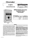
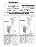
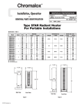
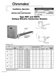
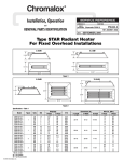
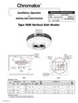
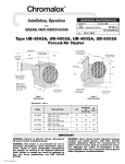
®
Chromalox
Installation, Operation
SERVICE REFERENCE
DIVISION
and
4
SALES
REFERENCE
MAINTENANCE INSTRUCTIONS
SECTION
MTO-LT
PD441-1
(Supersedes PD441)
161-303567-001
DATE
MARCH, 1999
Type MTO-LT
Pipe Insert Immersion Heater
A
Expansion Gap
B
2-3/8”
Max.
Spacer
2-1/16”
I.D. Min.
Type E2
Moisture-Tight
Explosion-Resistant
Enclosure
Pipe, Support &
Tank (by others)
Expansion Gap
3/4” Pipe Outlet
GENERAL
Model
kW
Volts
Phase
MTO-241LT
MTO-241LT
MTO-251LT
MTO-251LT
MTO-275LT
MTO-275LT
MTO-212LT
MTO-213LT
4
4
5
5
7.5
7.5
11.5
13
240
480
240
480
240
480
480
480
1
1
1
1
1
1
1
1
Dim. (In.)
A
B
127
127
163
163
211
211
319
367
120
120
156
156
204
204
312
360
Pipe
Thd.
2
2
2
2
2
2
2
2
WARNING: Calculate and allow for thermal expansion.
Pipe insert will expand upon heating. The rear end of the
pipe insert must remain free from the tank wall. Heating
elements will also expand upon heating and must not
extend to the end of the pipe insert.
Chromalox type MTO-LT screwplug immersion heater is designed
for insertion into a 2” or larger pipe.
WARNING: It is the responsibility of the purchaser of the heater to make
the ultimate choice of pipe material based upon his knowledge of the
chemical composition of the corrosive solution, character of the material
entering the solution and controls which he maintains on the process.
Chromalox cannot warrant any electric immersion heater against failure,
if such failure is the result of corrosion due to improper material selection by the user.
1. Heater Construction Characteristics:
A. High quality resistance wire held in place by compacted
Magnesium Oxide Refractory enclosed in an Incoloy® sheath.
B. Low to High Watt densities.
C. Explosion Resistant/Liquid-Tight E-2 terminal enclosures
are standard.
WARNING: Users should install adequate controls and
safety devices with their electric heating equipment.
Where the consequences of failure may be severe, backup controls are essential. Although the safety of the
installation is the responsibility of the user, Chromalox
will assist in identifying equipment options.
INSTALLATION
WARNING: Hazard of Shock. Disconnect all power
before installing heater.
1. Before installing, check your type MTO-LT pipe insert heater
for any damage that may have occurred during shipment.
2. Check to insure that the line voltage is the same as that stamped
on the nameplate.
3. Do not bend the heating elements. If bending is necessary,
consult factory.
4. IMPORTANT: Mount heater in the tank so that the liquid level
will always be above the effective heated portion of the heater (see
Figure 1). If the heater is not properly submerged, it may overheat
and damage the heating elements and create a possible fire hazard
due to excessive sheath temperatures.
5. Where work will pass over or near equipment, additional protection such as a metal guard may be needed.
© 2010 Chromalox, Inc.
Expected Low
Level of Liquid
This Portion of Heater Above Liquid Level and
Exposed to Air Will Lead to Premature Burnout of Element
WRONG
RIGHT
Expected Maximum
Sediment Level
Note: Locate Heater as low as possible for maximum liquid storage capacity. Heat
does not move downward.
Figure 1 - Open Tank Installation
INSTALLATION
6. Heater must not be operated in sludge.
7. Install the heater using a high quality pipe sealing compound on
the threads. Screw the heater into the opening (Figure 2). Tighten
sufficiently with wrench applied on the hex portion of the screwplug.
2”
Approx. 6” Cold
place.
A2. Position outlet and inlet in a vertical plane, facing upward to
prevent air pockets. Be sure all trapped air is removed from the
closed tank. Bleed the air out of the liquid piping system and
heater housing prior to operation.
A3. IMPORTANT: Heater should never be located at the highest
point in the system. Provide expansion tank, if necessary.
B. Vertical Position (Figure 4)
9. DANGER: Hazard of Fire — Since the heaters are
Drip Loop Recommended
to Minimize Passage of
Moisture Along Wiring
Into Terminal Wiring
and Connections
Outlet
Suitable
Wiring
Inlet
WARNING: Care must be taken to insure the heated portion does not extend into the
coupling area (see Dimensions).
Figure 2 - Exploded View Pipe Insert Heater Mounting
Locate Drain Pipe
at Bottom of Heater.
Sediment Deposits may be
Removed Through Drain Pipe
8. Closed Tank Installation
NOTE: When heating in closed vessels, controls and
back-up controls must be used to prevent buildup of temperature and/or pressure.
A. Horizontal Position (Figure 3)
Figure 4 - Closed Tank in Vertical Position
capable of developing high temperatures, extreme
care should be taken to:
A. Avoid contact between heaters and combustible materials.
B. Keep combustible materials far enough away to be free of the
effects of high temperatures.
Note: In a Forced Circulation System,
Use Pump In Inlet Side
Outlet
Maximum Sediment Level.
Install Heater Above
This Level But as Near to it as
Possible for Maximum Heated
Solution Storage Capacity
Inlet
Heater
Figure 3 - Closed Tank in Horizontal Position
A1. Place heater at an elevation so that natural circulation can take
WIRING
WARNING: Hazard of Shock. Any installation involving
electric heaters must be effectively grounded in accordance with the National Electrical Code.
1. Electric wiring to heater must be installed in accordance with
the National Electrical Code and with local codes by a qualified
person as defined in the NEC. WARNING: Use copper conductors only.
2. When element wattages are not equal, heaters must not be
connected in series.
3. Electrical wiring to heater should be contained in rigid conduit or in sealed flexible hose to keep corrosive vapors and liquids out of the terminal housing.
4. If flexible cord is employed, a watertight connector should be
used for entry of the cord into the terminal box. Outdoor applications require liquid-tight conduit and connectors.
5. Bring the power line wires through the opening in the terminal
box. Connect line wires as shown in the wiring diagram (see
Figure 5).
L-1
L-2
240-480V — Figure 5
OPERATION
1. Do not operate heaters at voltages in excess of that stamped on the
heater since excess voltage will shorten heater life.
2. Always maintain a minimum of 2” of liquid above the heater to
prevent exposure of the effective heated length. If the heater is not
properly submerged, it may overheat and shorten heater life. DO
NOT OPERATE HEATER IF TANK IS DRY.
3. Be sure all trapped air is removed from a closed tank. Bleed the air
out of the liquid piping system and heater housing prior to energizing.
Note: The tank or heating chamber in closed tank systems
must be kept filled with liquid at all times.
4. Keep heating elements above sediment deposits.
5. Low Megohm Condition — The refractory materials used in
electric heaters may absorb moisture during transit or when sub-
ject to a humid environment. This moisture absorption results in a
cold insulation resistance of less than twenty megohms. Normally,
this megohm value corrects itself after heatup and does not affect
heater efficiency or life.
A low megohm condition can easily be corrected by removing the
terminal hardware and terminal enclosure and baking the heater in
an oven at 350˚F for several hours, preferably overnight. Note:
The lid must be removed from the housing.
An alternate procedure is to energize the heaters at low voltage
until the megohm reading returns to normal. When energizing
heaters in air, the sheath temperature should not exceed 750˚F.
MAINTENANCE
WARNING: Hazard of Shock. Disconnect all power to
heater before servicing or replacing heaters.
1. Heaters should be checked periodically for coatings and corrosion
and cleaned if necessary.
2. The tank should be checked regularly for sediment around the
heater pipe insert as sediment can act as an insulator and shorten
heater life.
3. Remove any accumulated sludge deposits from around pipe
and from tank.
4. Check for loose terminal connections and tighten if necessary.
5. If corrosion is indicated in the terminal housing, check terminal
box gasket and replace if necessary. Check conduit layout to correct conditions that allow corrosion to enter the terminal housing.
6. Clean terminal ends of all contamination.
Limited Warranty:
Please refer to the Chromalox limited warranty applicable to this product at
http://www.chromalox.com/customer-service/policies/termsofsale.aspx.
2150 N. RULON WHITE BLVD., OGDEN, UT 84404
Phone: 1-800-368-2493
www.chromalox.com
TA - Q0 - EF
Litho in U.S.A.