1
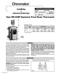
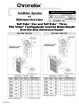
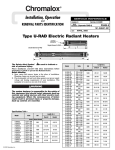
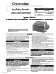
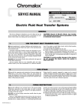
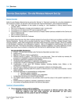
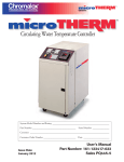
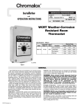
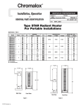
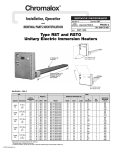
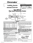
Chromalox
®
DIVISION
4
SECTION
SALES
REFERENCE (Supersedes PG435 )
VTS
PG435-1
161-304901-003
DATE
NOVEMBER, 2003
STAR-05A, -06A and -14A Cart Kit
For Conversion of Fixed Style to Portable Style
STAR-05 Portable Heater
After Conversion
See Page 2 – Fig. 2
STAR-05A Fixed Heater
Before Conversion
See Page 2 – Fig. 1
STAR-06A Portable Heater
After Conversion
See Page 3 – Fig. 2
STAR-06A Fixed Heater
Before Conversion
See Page 3 – Fig. 1
STAR-14A Portable Heater
After Conversion
See Page 4 – Fig. 2
STAR-14A Fixed Heater
Before Conversion
See Page 4 – Fig. 1
© 2010 Chromalox, Inc.
4.5 kW UNIT CONVERSION INSTRUCTIONS
UPPER BRACKET
3/8 X 1-1/2"
BOLT WITH
LOCKWASHER
AND NUT
INSTRUCTIONS FOR CONVERTING
A FIXED STYLE INTO A PORTABLE STYLE
(Installation of Cart making it a Portable Heater Voids UL Listing)
1. The kit (168-053169-079) that converts a 4.5 KW fixed style radiant heater into a portable includes the following parts. Verify that
all parts are included, if not, contact the Chromalox Service
Department at 1-800-368-2493.
(1)Lower Leg Assy. (7) 3/8-16 x 1-1/2” Long Bolts (4 Req’d)
(2)Upper Handle
(8) 3/8-16 Nuts (2 Req’d)
(3)Front Leg
(9) 3/8 Lockwashers (4 Req’d)
(4)Grip
(10) 10-32 x 1/2” Long Self Tapping
(5)Grille
Screw (2 Req’d)
(6)Cross Brace
2. Loosen nuts on upper bracket and remove bracket. Bolts, lockwashers and nuts will be reused, but upper bracket can be disregarded.
3. Using the bolts, lockwashers and nuts removed in step 3, slide
one of the bolts in the extrusion grove to the 4-5/16” dimension
and one 3/8” bolt to the 8-3/4” dimension.
4. Place the cross brace (7) on the bolt and secure i n place using
the lockwashers and nuts provided.
5. Place lower leg assy. (1) onto brace and upper 3/8” bolts. Slide
the 3/8-16 x 1-1/2” long bolts through the cross b race (7) and the
lower leg (1). Secure in place with lockwashers and nuts provided.
6. Slide the two (2) 3/8-16 x 1-1/2” long bolts into the top center
extrusion. Locate one at 3/4” and the other at 2-1/4” as shown.
FRONT VIEW
7. Place upper handle (3) onto two (2) bolts. Secure in place with
washers and nuts provided.
BACK VIEW
8. Slide grip (7) onto end of upper handle (5).
4.5 kW FIXED STYLE HEATER
9. Stand heater vertically. If heater does not sit evenly, loosen nuts
that secure lower leg assy and adjust accordingly.
10.Rotate heater back until handle (3) is on floor.
11.Install front leg (4) with two 10-32 x 1/2” long self tapping
screws (11).
12.Snap grille (6) into lip of extrusion.
4.5 kW FIXED STYLE HEATER
5
3
10 1/2" 9"
6
7
1
8
9
10
8 3/4"
4 5/1
11
FRONT VIEW
6
BACK VIEW
SIDE VIEW
2
6.0 kW UNIT CONVERSION INSTRUCTIONS
INSTRUCTIONS FOR CONVERTING
A FIXED STYLE INTO A PORTABLE STYLE
(Installation of Cart making it a Portable Heater Voids UL Listing)
11-1/2"
1. The kit (168-053169-079) that converts a 6.0 KW fixed style radiant
heater includes the following parts. Verify that all parts are included, if
not, contact the Chromalox Service Department at 1-800-368-2493.
(1) Lower Leg
(10) 1/4-20 x 1/2” Long Bolt (4 Req’d)
(2) Axle
(11) 1/4-20 Square nut (4 Req’d)
(3) Wheel (2 Req’d)
(12) Pop Rivet (4 Req’d)
(4) Cap (2 Req’d)
(13) No. 10 Sheet Metal Screw ( Req’d)
(5) Upper Handle
(14) 3/8-16 x 1-1/2” Long Bolts (2 Req’d)
(6) Front Leg
(15) 3/8-16 Nuts (2 Req’d)
(7) Grip
(16) 3/8 Lockwashers (2 Req’d)
(8) Grille
(17) 10-32 x 1/2” Long Self Tapping
(9) Baffle
Screw (2 Req’d)
23-5/8"
2. Using hammer tap cap (4) onto one end of axle (2). Slide one wheel
(3) onto axle. Slide end of axle through both holes of lower leg (1).
Slide remaining wheel onto portion of axle protruding through lower
leg. Tap cap on axle.
32-1/2"
3. Remove Lower Bracket by removing nuts and washers.
6.0kW Fixed Style Heater
4. Slide the two (2) 3/8” bolts in the outer extrusions to the 4-1/2”
dimension and the one (1) 3/8” bolt in the center extrusion to the 815/16” dimension.
3
5. Place lower leg assy made in step 2 onto the three (3) bolts. Secure in
place with washers and nuts removed in step 3.
2
6. Loosen three nuts on upper bracket and reposition to the 3” dimension
shown.
2 9
7. Slide the two 3/8-16 x 1-1/2” long bolts (14) into the top center extrusion. Locate one at 3/4” and the other at 2-1/4” as shown.
8. Place upper handle (5) onto two bolts. Secure in place with washers
and nuts provided.
5
6
9. Slide grip (7) onto end of upper handle (5).
5
10.Stand heater vertically. If heater does not sit evenly, loosen nuts that
secure lower leg assy and adjust accordingly.
1
6
11.Rotate heater back until handle (5) is on floor.
Scribe
Line on
Extrusion
12.Install front leg (6) with two 10-32 x 1/2” long self tapping
screws (17).
13.Install baffle (8) using pop rivets, if pop rivet gun is not available use
the No. 10 sheet metal screws.
14.Place grille prongs into slots of reflector using a counterclockwise rotation see Detail A. Insert 1/4-20 screws through looped end of grille
with 1/4-20 square nut on opposite side. Tighten screws with screw
driver.
15.If fixed heater is being converted to a portable by the factory, then drill
out nameplate rivets and replace nameplate with 196-891789-004.
2x Loop of Grill
7
10
4
8
6.0 kW Fixed Style Heater
Modified to add cart, baffle and grille
2x Prong of Grill
3
13.5 kW UNIT CONVERSION INSTRUCTIONS
INSTRUCTIONS FOR CONVERTING
A FIXED STYLE INTO A PORTABLE STYLE
(Installation of Cart making it a Portable Heater Voids UL Listing)
1. The kit (168-053169-057) that converts a 13.5 kW fixed style radiant heater
into a protable includes the following parts. Verify that all parts are included,
if not, contact the Chromalox Service Department at 1-800-368-2493.
(1) Lower Leg
(7) Grille (2 Req’d)
(2) Axle
(8) Baffle
(3) Wheel (2 Req’d)
(9) 1/4-20 x 1/2” long bolt (4 Req’d)
(4) Cap (2 Req’d)
(10) 1/2-20 Square nut (4 Req’d)
(5) Upper Handle
(11) Pop Rivet (6 Req’d)
(6) Grip (2 Req’d)
(12) No. 10 Sheet Metal Screw (6 Req’d)
11-1/2"
23-5/8"
2. Using hammer tap cap (4) onto one end of axle (2). Slide one wheel (3)
onto axle. Slide end of axle through both holes of lower leg (1). Slide
remaining wheel onto portion of axle protruding through lower leg. Tap
cap on axle.
3. Remove Lower Bracket by removing nuts and washers.
55-5/8"
4. Slide the two 3/8” bolts in the outer extrusions to the 7-3/32” dimension
and the one 3/8” bolt in the center extrusion to the 11-17/32” dimension.
13.5 kW Fixed Style Heater
5. Place lower leg assy made in step 2 onto the three bolts. Secure in place
with washers and nuts removed in step 3.
6. Remove upper bracket by removing nuts and washers.
7. Place upper handle (5) onto three bolts. secure in place with washers and
nuts removed in step 6.
8. Slide grips (6) onto ends of upper handle.
9. Stand heater vertically. If heater does not sit evenly, loosen nuts that
secure lower leg assy and adjust accordingly.
3
6
10. Rotate heater back until handle (5) is on floor.
5
3
2
11. Install baffle (8) using pop rivets, if pop rivet gun is not available use the
NO. 10 sheet metal screws.
12. Place grille prongs into slots of reflector using a counterclockwise rotation
see Detail A. Insert 1/4-20 bolts (9) through looped end of grille with 1/420 square not (10) on opposite side. Tighten screws with screw driver.
2
13. Install remaining grille in same manner as step 12.
14. If fixed heater is being converted to a portable by the factory, then drill out
nameplate rivets and replace nameplate with 196-891789-004.
5
6
7
1
9
2x Loop of Grill
4
5
6
3
8
Scribe Line
on Extrusion
2x Prong of Grill
4
13.5 kW Fixed Style Heater
Modified to add cart, baffle and grille
4
GENERAL
IMPORTANT: SAVE THESE INSTRUCTIONS
FIRE HAZARD. Do not use as a residential or
household heater. Keep combustible material away
from heater. Do not operate heater where flammable vapors, gases or liquids are present.
To avoid personal injury read “IMPORTANT
INSTRUCTIONS” on this page before installation or
operation of heater.
IMPORTANT INSTRUCTIONS
When using electrical appliances, basic precautions should
always be followed to reduce risk of fire, electric shock and injury
to persons, including the following:
1. Read all instructions before using this heater.
2. This heater is hot when in use. To avoid burns, do not let bare
skin touch hot surfaces. Keep combustible materials, such as
furniture and papers at least 7 feet from the front of the heater.
3. Do not leave heater unattended while in operation.
4. Always disconnect heater when not in use.
5. Do not use outdoors in areas subject to wind.
6. Connect to properly grounded outlets or building ground.
7. This heater has hot surfaces. Do not use it in areas where gasoline, paint or flammable liquids are used or stored.
8. Use this heater only as described in this manual. Any other use
not recommended by the manufacturer may cause fire, electric
shock or injury to persons.
9. In order to prevent equipment damage, protect with a ground
fault device such as Chromalox STAR-TG series monitor.
10. These instructions amend the fixed instructions that came
with the original heater.
SAVE THESE INSTRUCTIONS
WIRING
Use type “SO” or equal power cord. Refer to table 1 for proper wire gage and number of conductors.
Table 1
Model
Amperage
1 Phase
3 Phase
Cord Ga./No. cond.
1 Phase
3 Phase
Volts
KW
STAR-05-81-P
STAR-05-21-P
STAR-05-71-P
STAR-05-41-P
STAR-05-61-P
208
240
277
480
600
4.5
4.5
4.5
4.5
4.5
21.6
18.8
16.2
9.4
7.5
NA
NA
NA
NA
NA
12/3
12/3
14/3
14/3
14/3
NA
NA
NA
NA
NA
STAR-06-83-P
STAR-06-23-P
STAR-06-71-P
STAR-06-43-P
STAR-06-63-P
208
240
277
480
600
6
6
6
6
6
28.8
25.0
21.7
12.5
10.0
16.7
14.4
—
7.2
5.8
10/3
10/3
10/3
12/3
12/3
12/4
12/4
—
12/4
12/4
STAR-14-83-P
STAR-14-23-P
STAR-14-71-P
STAR-14-43-P
STAR-14-63-P
208
240
277
480
600
13.5
13.5
13.2
13.5
13.5
NR
NR
47.7
28.1
22.5
37.5
32.5
—
16.2
13.0
NR
NR
6/3
10/3
10/3
6/4
8/4
—
12/4
12/4
NA - Not Available
NR - Not Recommended
RENEWAL PARTS IDENTIFICATION
Grills for STAR-14 (2) . . . . . . . . . . . . . . . . . . . 134-304892-003
Hardware for Mounting Grills GR14TW
Screw . . . . . . . . . . . . . . . . . . . . . . . . . . . . . 248-075512-123
Square Nut . . . . . . . . . . . . . . . . . . . . . . . . . 200-048688-007
Wheel . . . . . . . . . . . . . . . . . . . . . . . . . . . . . . . . 333-557518-001
End Cap . . . . . . . . . . . . . . . . . . . . . . . . . . . . . . 039-510848-001
Vinyl Grip. . . . . . . . . . . . . . . . . . . . . . . . . . . . . 024-304894-001
Grill for STAR-06. . . . . . . . . . . . . . . . . . . . . . . 143-304892-001
5
Limited Warranty:
Please refer to the Chromalox limited warranty applicable to this product at
http://www.chromalox.com/customer-service/policies/termsofsale.aspx.
2150 N. RULON WHITE BLVD., OGDEN, UT 84404
Phone: 1-800-368-2493
www.chromalox.com