1
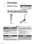
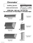
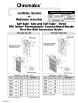
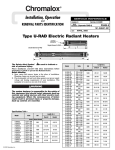
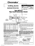
Chromalox
®
DIVISION
4
SECTION
VTS
SALES
(Supersedes ) PG433)
REFERENCE (Supersedes
PG433-1
161-304901-001
DATE
MAY, 2003
Type STAR Radiant Heater
For Portable Installations
Specifications – Table 1
Model
Figure
STAR-02A-11-PC
STAR-02A-81-P
STAR-02A-21-P
STAR-02A-71-P
STAR-02A-41-P
STAR-02A-61-P
KW
120
208
240
277
480
600
1.5
2
2
2
2
2
12.5
9.6
8.3
7.2
4.2
3.3
NA
NA
NA
NA
NA
NA
5118
6824
6824
6824
6824
6824
2
208
240
277
480
600
4.5
4.5
4.5
4.5
4.5
21.6
18.8
15.9
9.4
7.5
NA
NA
NA
NA
NA
15354
15354
15354
15354
15354
3
208
240
277
480
600
6
6
6
6
6
28.8
25.0
21.7
12.5
10.0
16.7
14.4
—
7.2
5.8
20472
20472
20472
20472
20472
4
208
240
277
480
600
13.5
13.5
13.3
13.5
13.5
NR
NR
47.7
28.1
22.5
37.5
32.5
—
16.2
13.0
46062
46062
45038
46062
46062
1
STAR-05A-81-P
STAR-05A-21-P
STAR-05A-71-P
STAR-05A-41-P
STAR-05A-61-P
STAR-06A-83-P
STAR-06A-23-P
STAR-06A-71-P
STAR-06A-43-P
STAR-06A-63-P
STAR-14A-83-P
STAR-14A-23-P
STAR-14A-71-P
STAR-14A-43-P
STAR-14A-63-P
Amperage
1 Phase
3 Phase
Volts
BTU
A Height
28-1/2
49
32-1/2
55-5/8
Dimensions (In.)
B Width
D Depth
11-3/8
11-3/8
23-5/8
23-5/8
Cord Ga./No. cond.
1 Phase
3 Phase
Comes w/cord & plug
14/3
NA
14/3
NA
14/3
NA
14/3
NA
14/3
NA
11-3/4
11-3/4
12/3
12/3
14/3
14/3
14/3
NA
NA
NA
NA
NA
11-1/2
10/3
10/3
10/3
12/3
12/3
12/4
12/4
—
12/4
12/4
11-1/2
NR
NR
6/3
10/3
10/3
6/4
6/4
—
12/4
12/4
NA - Not Available
NR - Not Recommended
11-3/4"
11-3/4"
11-3/8"
11-3/8"
28-1/2"
49"
Side View
Front View
Figure 1
© 2010 Chromalox, Inc.
Side View
Front View
Figure 2
GENERAL
23-5/8"
11-1/2"
11-1/2"
23-5/8"
55-5/8"
32-1/2"
Side View
Front View
Side View
Figure 3
Front View
Figure 4
IMPORTANT:
SAVE THESE INSTRUCTIONS
To avoid personal injury read “IMPORTANT
INSTRUCTIONS” on this page before installation or
operation of heater.
FIRE HAZARD. Do not use as a residential or
household heater. Keep combustible material away
from heater. Do not operate heater where flammable vapors, gases or liquids are present.
IMPORTANT INSTRUCTIONS
When using electrical appliances, basic precautions should
always be followed to reduce risk of fire, electric shock and injury
to persons, including the following:
1. Read all instructions before using this heater.
2. This heater is hot when in use. To avoid burns, do not let bare
skin touch hot surfaces. Keep combustible materials, such as
furniture and papers at least 7 feet from the front of the heater.
3. Do not leave heater unattended while in operation.
4. Always disconnect heater when not in use.
5. Do not use outdoors in areas subject to wind.
6. Connect to properly grounded outlets or building ground.
7. This heater has hot surfaces. Do not use it in areas where gasoline, paint or flammable liquids are used or stored.
8. Use this heater only as described in this manual. Any other use
not recommended by the manufacturer may cause fire, electric
shock or injury to persons.
9. In order to prevent equipment damage, protect with a ground
fault device such as Chromalox STAR-TG series monitor.
10.
SAVE THESE INSTRUCTIONS
2
WIRING
2. The heater connection points are located in the gasketed terminal enclosure. To remove cover, remove screw(s) on the cover.
Remove the cover to expose wiring connection points.
3. A green ground terminal is provided in the bottom of the enclosure. The ground wire should be connected before other connections are made.
4. Use type "SO" or equal cord.
Refer to Table 1 for proper cord gage and number of conductors.
5. All 3 element heaters are factory pre-wired for 3-phase delta
operation. Some units can be converted to single phase operation
by changing the wiring. Refer to Table 1 for those heaters that
can be converted to single phase. The appropriate wiring diagram (Figure 4) is also located on the bottom of the enclosure.
ELECRIC SHOCK HAZARD. Disconnect all power
before installing or servicing heater. Failure to do
so could result in personal injury or property damage. Heater must be effectively grounded in accordance with the National Electrical Code, NFPA 70.
All electrical wiring must be done by a qualified
person in accordance with National Electrical Code
(NEC) and meet all state and local regulations.
1. Use heater only at the voltage specified on the nameplate.
1.
2.
3.
4.
5.
6.
7.
8.
9.
INSTRUCTIONS FOR FIELD CONVERSION FROM 3 PHASE TO 1 PHASE:
Remove nuts from all terminals.
Remove all pigtail leads and hat shaped buss bar.
Remove end of leadwire on terminal 5 and slip onto terminal 4.
Remove leadwire attached to instruction sheet and connect between terminals 4 and 6.
Install hat shaped buss bar between terminals 3 and 5.
Place pigtail lead marked “L1” on to terminal 2 and pigtail lead marked “L2” on to terminal 6.
Install nuts.
Connect entrance wiring to pigtail leads “L1” and “L2”. Connect ground to screw provided.
Inspect to make sure wiring is per “Single Phase Wiring” above.
OPTIONAL ACCESSORIES
Plugs
Single and three phase with ground. Available in nonlocking
and locking. See Chart B.
Chromalox STAR series radiant heaters can be field modified by
adding optional kits. Refer to Chart A and B to select the proper kit.
Disconnect Kit
The disconnect kit consists of a complete assembly consisting
of a disconnect switch (3 Pole), power terminal block and all hardware to complete the installation. This kit can be mounted to both
the fixed, overhead heater or the portable heater; see instruction
bulletin PG436 for details.
Tip Over and Ground Fault Kits
Star Tip Series Kit attaches to portable heater and de-energizes
the heater in the event it is tipped over.
Star-TG Series Kit combines the tip over and ground fault feature for portable heaters. See installation bulletin PG436.
Cord Kits
Cord kits consist of 25 feet of 90°C cable and a right angle cord
fitting which can connect directly to the heater terminal box or disconnect switch (if used). See installation bulletin PF491 for details
3
OPTIONAL ACCESSORIES
Chart A - Kit Selection
Disconnect
Kit
Tipover
Kit
Tipover
w/Ground Fault
STAR-02A-11-PC
NA
NA
NA
STAR-02A-81-P
NA
NA
NA
PCN 295670
NA
STAR-02A-21-P
NA
NA
NA
PCN 295670
NA
STAR-02A-71-P
NA
NA
NA
PCN 295670
NA
STAR-02A-41-P
NA
NA
NA
PCN 295670
NA
STAR-02A-61-P
NA
NA
NA
PCN 295670
NA
STAR-05A-81-P
NA
NA
NA
PCN 295662
NA
STAR-05A-21-P
NA
NA
NA
PCN 295662
NA
STAR-05A-71-P
NA
NA
NA
PCN 295670
NA
STAR-05A-41-P
NA
NA
NA
PCN 295670
NA
STAR-05A-61-P
NA
NA
NA
PCN 295670
NA
STAR-06A-83-P
PCN 340662
PCN 340670
PCN 340726
PCN 295443
PCN 295435
STAR-06A-23-P
PCN 340662
PCN 340689
PCN 340734
PCN 295443
PCN 295435
STAR-06A-71-P
PCN 340662
PCN 340697
PCN 340742
PCN 295443
NA
STAR-06A-43-P
PCN 340662
PCN 340700
PCN 340750
PCN 295662
PCN 295427
Model
Single Phase
Cord Set
Three Phase
Cord Set
Comes w/cord & plug
STAR-06A-63-P
PCN 340662
PCN 340718
PCN 340769
PCN 295662
PCN 295427
STAR-1A4-83-P
PCN 340662
PCN 340670
PCN 340726
NA
PCN 295494
PCN 295478
STAR-14A-23-P
PCN 340662
PCN 340689
PCN 340734
NA
STAR-14A-71-P
PCN 340662
PCN 340697
PCN 340742
PCN 295486
NA
STAR-14A-43-P
PCN 340662
PCN 340700
PCN 340750
PCN 295443
PCN 295435
STAR-14A-63-P
PCN 340662
PCN 340718
PCN 340769
PCN 295443
PCN 295427
Chart B - Plug Selection
—
Fits Cable Dia.
Plug Type
Model
Description
Volts
Amps
Configuration
NEMA #
ANSI #
.385”-.780”
Locking
PGL-15-20
3 Pole, 4 Wire
250
20
L15-20
C73.85
.385”-.780”
Locking
PGL-15-30
3 Pole, 4 Wire
250
30
L15-30
C73.86
.595”-1.150”
Locking
PGL-16-30
3 Pole, 4 Wire
480
30
L16-30
C73.88
.595”-1.150”
Locking
PGL-17-30
3 Pole, 4 Wire
600
30
L17-30
C73.89
.750”-1.125”
Locking
PGL-3763C
2 Pole, 4 Wire
600
50
—
—
.750”-1.125”
Locking
PGL-3765C
3 Pole, 4 Wire
600
50
—
—
.625”-1.187”
Non Locking
PGN-6-50
2 Pole, 3 Wire
250
50
6-50
C73.53
.390”-.775”
Non Locking
PGN-15-20
3 Pole, 4 Wire
250
20
15-20
C73.59
.750”-1.250”
Non Locking
PGN-15-50
3 Pole, 4 Wire
250
50
15-50
C73.61
The above plugs are designed to be used with specific ranges of cable diameters. If not used with Chromalox Cable Kits, check cable manufacturers cable diameter to be sure plug fits selected cable.
4
MAINTENANCE
6. Remove wires and jumper straps as required to replace the
failed heating element(s).
7. Remove bulkhead fitting nuts and washers.
8. Remove failed element and replace with a new element.
Replace only with genuine Chromalox "Arctic End" elements. Use of other elements will cause excess temperatures
inside terminal box.
9. Place gasket on the bulkhead fitting and insert terminals and
fittings into the element holes in the terminal box.
10. Place washers and nuts on bulkhead fittings and tighten.
11. Replace wiring and jumper straps ( see Fig. 4).
12. Reassemble by following the reverse procedures (steps 5
through 1)
ELECRIC SHOCK HAZARD. Disconnect all power
before servicing or replacing heating elements.
The reflectors should be kept clean to obtain the maximum
radiant output.
Element Replacement
1. Remove Terminal Box Cover.
2. Disconnect lead wires from heater terminals.
3. Remove safety grills (if installed).
4. Remove retainer screw located on the reflector at the terminal end.
5. Loosen (2), 3/8" nuts from the terminal box bracket located on
the back of the heater and slide the entire heating element
assembly out of the reflector assembly.
RENEWAL PARTS IDENTIFICATION
Model
STAR-02A-11-PC
STAR-02A-81-P
STAR-06A-83-P
STAR-02A-21-P
STAR-06A-23-P
STAR-02A-71-P
STAR-06A-71-P
STAR-02A-41-P
STAR-06A-43-P
STAR-02A-61-P
STAR-06A-63-P
STAR-05A-81-P
STAR-14A-83-P
STAR-05A-21-P
STAR-14A-23-P
STAR-05A-71-P
STAR-14A-71-P
STAR-05A-41-P
STAR-14A-43-P
STAR-05A-61-P
STAR-14A-63-P
Element***
PCN 106059
Element Housing
Reflector
PCN 106067
PCN 106075
PCN 106083
234-891755-004
PCN 106091
PCN 106104
PCN 106403
PCN 106411
PCN 106796
234-891-755-002
PCN 106964
PCN 106972
Safety Screen
PCN 111878
PCN 111878
PCN 340638
PCN 111878
PCN 340638
PCN 111878
PCN 340638
PCN 111878
PCN 340638
PCN 111878
PCN 340638
PCN 111894
PCN 340857
PCN 111894
PCN 340857
PCN 111894
PCN 340857
PCN 111894
PCN 340857
PCN 111894
PCN 340857
Terminal Box
Gasket
132-304879-004
132-304879-004
132-304879-003
132-304879-004
132-304879-003
132-304879-004
132-304879-003
132-304879-004
132-304879-003
132-304879-004
132-304879-003
132-304879-004
132-304879-003
132-304879-004
132-304879-003
132-304879-004
132-304879-003
132-304879-004
132-304879-003
132-304879-004
132-304879-003
*** Includes element supports
Parts Common to All Models:
Bulkhead fitting gasket . . . . . . . . . . . . . . . 132-895735-008
Bulkhead fitting washer . . . . . . . . . . . . . . . 328-890675-014
Bulkhead fitting nut . . . . . . . . . . . . . . . . . . 200-890615-031
Element Support . . . . . . . . . . . . . . . . . . . . . 291-304869-002
Vinyl Grip . . . . . . . . . . . . . . . . . . . . . . . . . . 024-304894-001
Parts Common to STAR, 06A-P and 14A-P Models:
Wheel . . . . . . . . . . . . . . . . . . . . . . . . . . . . . 333-557518-001
End Cap . . . . . . . . . . . . . . . . . . . . . . . . . . . 039-510848-001
5
Limited Warranty:
Please refer to the Chromalox limited warranty applicable to this product at
http://www.chromalox.com/customer-service/policies/termsofsale.aspx.
2150 N. RULON WHITE BLVD., OGDEN, UT 84404
Phone: 1-800-368-2493
www.chromalox.com