1
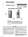
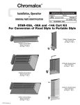
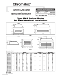
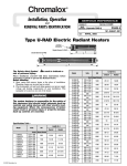
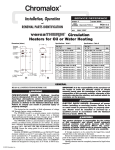
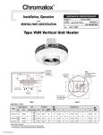
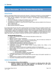
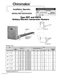
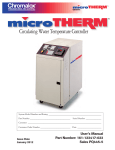
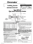
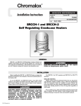
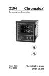
®
Chromalox
Installation, Operation
SERVICE REFERENCE
DIVISION
and
4
SALES
REFERENCE
Maintenance Instructions
SECTION
TPR/TPF
PD437-4
(Supersedes PD437-3)
161-074306-001
SEPTEMBER, 1998
DATE
Tuff-Tube™ One and Tuff-Tube™ Three
PFA Teflon® Thermoplastic Covered Metal Sheath
Over-the-Side Immersion Heater
TUFF-TUBE™ ONE (TPR)
TUFF-TUBE™ THREE (TPF)
7/8 Dia. each side
for 1/2 in. conduit
Tank Lip
7/8 Dia. each side
for 1/2 in. conduit
Tank Lip
Plastic guard cover removed
for illustration purposes.
Plastic guard cover removed
for illustration purposes.
C
C
B
A
A
B
D
D
Mounting Hole Location
Mounting Hole Location
Specifications — Type TPR — Figure 1
Model
TPR-101
TPR-102
TPR-202
TPR-204
TPR-302
TPR-304
TPR-402
TPR-404
TPR-602
TPR-604
TPR-802
TPR-804
Watts
1000
2000
3000
4000
6000
8000
Volts
Phase
120
240
240
480
240
480
240
480
240
480
240
480
1
1
1
1
1
1
1
1
1
1
1
1
*B Dimension is heated section.
© 2010 Chromalox, Inc.
Specifications — Type TPF — Figure 2
Dimensions (In.)
A
B*
C**
D
13
6
7
15
21
12
9
23
26
17
9
28
31
22
9
33
42
33
9
44
53
44
9
55
**C Dimension is cold section.
Model
TPF-302
TPF-304
TPF-402
TPF-404
TPF-602
TPF-604
TPF-802
TPF-804
TPF-1002
TPF-1004
Watts
3000
4000
6000
8000
10000
Volts
Phase
240
480
240
480
240
480
240
480
240
480
3
3
3
3
3
3
3
3
3
3
*B Dimension is heated section.
Dimensions (In.)
A
B*
C**
D
20
11
9
22
23
14
9
25
30
21
9
32
37
28
9
39
44
35
9
46
**C Dimension is cold section.
GENERAL
WARNING: This heater is not intended for use in
hazardous atmospheres where flammable vapors,
gases, liquids or other combustible atmospheres are
present as defined in the National Electrical Code.
Failure to comply can result in explosion or fire.
Chromalox type TPR and TPF over-the-side immersion heaters
are especially suited for heating corrosive solutions to 212˚F.
WARNING: It is the responsibility of the purchaser of
the heater to make the ultimate choice of sheath
material based upon his knowledge of the chemical
composition of the corrosive solution, character of
the materials entering the solution, and controls
which he maintains on the process. Chromalox cannot warrant any electric immersion heater against
failure by sheath corrosion if such failure is the result
of operating conditions beyond our control.
1. Heater Construction Characteristics
A. High quality resistance wire held in place by compacted magnesium oxide in stainless steel sheath and thermoplastic coated.
B. Medium Watt Density — 20 watts per sq. inch.
C. Light weight and low profile.
D. Removable polypropylene guard is standard.
E. PVC mounting bracket is standard for easy installation.
F. Element terminals are encapsulated with a self-hardening
vapor barrier.
G. Manual reset cutout to shut off heater in an overtemperature condition is standard.
WARNING: Users should install adequate controls
and safety devices with their electric heating equipment. Do not use the overtemperature control as a
level control device, damage may result to the coating should an overtemperature condition exist.
Where the consequences of failure may be severe,
back-up controls are essential. Although the safety
of the installation is the responsibility of the user,
Chromalox will be glad to make equipment recommendations.
INSTALLATION
WARNING: Hazard of Electric Shock. Disconnect all
power before installing heater.
1. CAUTION: Do not scrape or scratch thermoplastic coating
on heating elements. Damage could result.
2. Before installing the type TPR and TPF heater, inspect it for
possible damage which may have occurred during shipment.
Also, check to insure the line voltage is the same as that on the
nameplate.
3. WARNING: Mount heater in the tank so the liquid level will always be above the effective heated
portion of the heater. If heater is not properly sub-
merged, it will overheat and damage the heating
elements and create a possible fire due to excessive sheath temperature. (NOTE: Level indicator on
plastic guard is 2” above heated section. Do not use the overtemperature control as a level control device, damage may result to
the coating should an overtemperature condition exist.)
4. In an electroplating operation the heaters are not, under any
circumstance, to be placed between the electrodes and the work.
5. DANGER: Hazard of Fire and Toxic Fumes. Since
these heaters are capable of developing high temperatures,
care should be taken to maintain liquid level above heated
portion (Dimension B of Figures 1 and 2) of heater.
WIRING
WARNING: Hazard of Electric Shock. Any installation
involving electric heaters must be effectively grounded in accordance with the National Electrical Code.
1. Electrical wiring to heater must be installed in accordance
with the National Electrical Code and local codes by a qualified person.
2. Wire heater with manual reset thermal cutout as shown in
Figures 3 thru 7.
NOTE: 1) Manual reset thermal cutout rating 25 Amps 120-277
Vac; 2) Customer supplied thermostat wiring not shown.
3. WARNING: Entrance of corrosive fumes and
vapors into the enclosure may damage internal
parts. Use liquid-tight fitting and liquid-tight
conduit for wiring entrance. Unused conduit
opening must be sealed with snap-in plug provided. Assemble terminal cover tightly.
OPERATION
1. Do not operate heater at voltages in excess of that stamped on
the heater since excess voltage will shorten heater life.
2. Always maintain a minimum of 2” of solution above the heated portion of the element to prevent exposure of the effective
heated length. If the heater is not properly submerged, it may
overheat and shorten heater life. Do not operate heater if dry.
(Note: Heated portion of element is Dimension B of Figures 1
and 2). Do not use the overtemperature control as a level control
device, damage may result to the coating should an overtemperature condition exist.
3. Sludge should not be allowed to build-up to the point where it
contacts heater as this can lead to premature heater failure.
4. Maximum recommended process temperature is 212˚F.
5. If manual reset cutout trips, disconnect power to heater and
check for cause of overheat condition. Check heater elements and
coating for possible damage due to an overheat condition. Correct
condition, then remove heater terminal cover and push black reset
button to reset the cutout. Assemble terminal cover tightly before
re-energizing heater.
MAINTENANCE
WARNING: Hazard of Electric Shock. Disconnect all
power before servicing or replacing heater.
1. Heaters should be checked periodically for coating and corrosive buildup and cleaned if necessary.
2. Tank should be checked regularly for sediment around the end
of heater as this sediment can act as an insulation and shorten
heater life.
3. Note: Before thermoplastic heater is removed from solution, it
should be allowed to cool from 15 to 20 minutes.
4. CAUTION: Do not scratch or scrape elements when cleaning. Cleaning should be done chemically.
5. To remove plastic guard - disconnect all plastic hardware
attachments on guard assembly.
WIRING DIAGRAMS
2 Pole Contactor
(Customer Supplied)
Line Voltage
1
2
120V or 240V
Control Circuit
C2
Cutout
C1
Green
Ground
Factory
Field
Figure 3
Single Phase (All TPR Heaters)
Cutout
1
C2
C1
120V Line Voltage
2
Green
Ground
Factory
Field
Figure 4
Alt. Single Phase (TPR-101 Only)
3 Pole Contactor
(Customer Supplied)
1
Line Voltage
2
3
3
2
120V or 240V
Control Circuit
1
C2
Cutout
Ground
C1
Green
Factory
Field
Figure 5
Three Phase (TPF-302, -304, -402, -404)
WIRING DIAGRAMS
3 Pole Contactor
(Customer Supplied)
Line Voltage
1
2
3
120V or 240V
Control Circuit
1
2
3
C2
Cutout
Ground
C1
Green
Factory
Field
Figure 6
Three Phase (TPF-602, -604, -802, -804, -1002, -1004)
2 Pole Contactor
(Customer Supplied)
Line Voltage
1
2
3
3
2
1
120V or 240V
Control Circuit
C2
Cutout
C1
Ground
Green
Factory
Field
Figure 7
Single Phase (TPF Rated 3kW and 4kW, 240 or 480 Volt)
Limited Warranty:
Please refer to the Chromalox limited warranty applicable to this product at
http://www.chromalox.com/customer-service/policies/termsofsale.aspx.
2150 N. RULON WHITE BLVD., OGDEN, UT 84404
Phone: 1-800-368-2493
www.chromalox.com
TA - Q0 - EF
Litho in U.S.A.