1
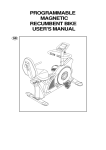
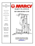
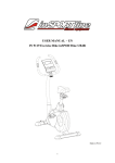
ELLIPTICAL TRAINER
PRODUCT CODE: E7000D
Escalade International Limited
Pleasant Road, Penllergaer, Swansea. SA4 9GE
Tel: 00 44 1792 222 550 Fax 00 44 1792 895 781
www.escaladesports.co.uk
[email protected]
Important Safety Information
Weight Limit Capacities
3
Exploded Diagram
5
Parts List
6
Parts Identifier
7
Assembly Instructions
8 - 11
User guide
12
Computer
13
Principles of Exercise
15
Fault Finding Chart
17
Additional Information
17
Warranty & Ordering Parts
18
Maintenance & Specifications
18
Supplied by
Escalade International Ltd
Pleasant Road
Penllergaer
Swansea
SA4 9GE
Tel: 00 44 1792 222550
Fax: 00 44 1792 895781
www.escaladesports.co.uk
E mail: [email protected]
2
IMPORTANT SAFETY INFORMATION
READ ALL INSTRUCTIONS BEFORE USING
THIS OWNER’S MANUAL CONTAINS ASSEMBLY, OPERATION, MAINTENANCE AND SAFETY
INFORMATION. IN THE INTEREST OF SAFETY, PLEASE MAKE CERTAIN THAT YOU READ
AND UNDERSTAND ALL THE INFORMATION BELOW.
1. This elliptical is intended for class H (H=Domestic) use only. It is not designed for
commercial use.
2. This machine has been tested to BS EN 957 Parts 1:1996, 1+A1:1998 and 5:1996.
3. Read the OWNER’S OPERATION MANUAL and all accompanying literature and follow it
carefully before using your elliptical.
4. Keep children and pets away from the Elliptical at all times. Do not leave children
unattended in the same room with the Elliptical. The Elliptical is not a toy and therefore
parents and guardians should be aware of the natural tendency for children to play, leading
to situations and behaviour for which the Elliptical is not intended.
5. If children are allowed to use the Elliptical their physical/mental development and above all,
temperament should be taken into account. Constant supervision is therefore needed.
6. Position the Elliptical on a clear levelled surface which is clear of all obstacles as not to
restrict movement whilst exercising. DO NOT use the Elliptical near water or outdoors.
7. Exercise equipment has moving parts. In the interest of safety, keep others, especially
children, at a safe distance while exercising.
8. Never hold your breath while exercising. Breathing should remain at a normal rate in
conjunction with the level of exercise being performed.
9. Rest adequately between workouts. Muscle tone develops during these rest periods.
Beginners should work out twice a week and increase gradually to 4 to 5 times per week.
10. Remove all jewellery, including rings, chains and pins before commencing exercise.
11. Always wear suitable clothing and footwear during exercise. Do not wear loose fitting
clothing that could become entangled with the moving parts of your exercise machine.
IMPORTANT!!! THE MAXIMUM RECOMMENDED WEIGHT CAPACITY FOR YOUR
ELLIPTICAL IS 150KGS.
3
WARNING: Before commencing any exercise program, please consult your family
physician. If at any time during exercise you feel faint, dizzy or experience pain, stop and
consult your family physician. In the event any of the above mentioned warnings are
breached by the consumer, the manufacturer may use same as a defence to any claim for
injuries, damage or loss. The above warnings are in no way intended to limit or modify the
consumer’s remedies for breach of warranties. They are being supplied strictly to ensure
the safety of the individuals using this product.
IMPORTANT: Read all instructions carefully. Assemble the Elliptical in
accordance with the steps in the manual. Box spanners and an allen key
are included for assembly. Lay out all parts on the floor. Make sure that
you have all the parts listed below before beginning assembly. In case of
discrepancy, please call our Customer Service Department at the number
listed on page 18 of this manual.
OUR ELLIPTICALS ARE MANUFACTURED WITH CARE AND ATTENTION. QUALITY AND CUSTOMER
SATISFACTION ARE OUR MAIN AIM. HOWEVER THINGS MAY GO WRONG. IF YOU SHOULD HAVE ANY
PROBLEMS OR FIND YOU HAVE PARTS MISSING, PLEASE CONTACT ESCALADE DIRECTLY.
HOWEVER, THERE MAY BE EXCEPTIONAL CIRCUMSTANCES WHERE YOU MAY WISH TO RETURN THE
ELLIPTICAL. WE THEREFORE ASK THAT YOU RETAIN ALL PACKAGING UNTIL YOU ARE COMPLETELY
SATISFIED.
NOTE: SOME ITEMS OF HARDWARE MAY ALREADY BE PRE-ASSEMBLED ONTO YOUR ELLIPTICAL.
4
EXPLODED DIAGRAM
5
PARTS LIST
PART
NO,
1
2
3
DESCRIPTION
QTY
PART NO, DESCRIPTION
REAR STABILIZER
1 PCS
41
REAR TRANSPARENT COVER
1 PCS
ADJUSTING CAP
CARRIAGE BOLT FOR STABILIZER
M8*75L
2 PCS
42
2 PCS
4 PCS
43
DISC FOR COVER
FOAM GRIP FOR RIGHT & LEFT
HANDLEBAR
2 PCS
4
ACORN NUT
8 PCS
44
WAVY WASHER φ 17.5xφ25x0.3t
4PCS
5
CURVED WASHER ( ø8*2t)
16 PCS
45
PEDAL ARM ( RIGHT )
1 PCS
6
FRONT STABILIZER
1 PCS
46
PEDAL ARM ( LEFT )
1 PCS
7
TRANSPORTATION WHEEL
2 PCS
47
COMPUTER CABLE UPPER
1PCS
8
HANDLEBAR POST
1 PCS
48
BEARING FOR FLYWHEEL
1 PCS
9
COVER FOR HANDLEBAR POST
1 PCS
49
BUSHING FOR FLYWHEEL
1PCS
10
SCREW FOR HANDLEBAR POST M8*16L
4 PCS
50
2PCS
11
MOVEABLE HANDLEBAR ( LEFT )
1 PCS
51
12
MOVEAVLE HANDLEBAR ( RIGHT )
1 PCS
52
METAL BUSHING 38.2mm
SCREWS FOR FIXING
COMPUTER M5*10L
GEAR BOX
1PCS
13
AXLE FOR MOVEABLE HANDLEBAR
1 PCS
53
COMPUTER CABLE LOWER
1PCS
RUBBER SLEEVE ø26* ø32*8.5L
(A)
SPRING WASHER FOR FIXING
4PCS
14
TEFLON WASHER FOR MOVE( ø25*1t)
4PCS
54
15
FLAT WASHER ( ø10*2t)
4 PCS
55
16
HEX BOLT ( M8*P1.0*20L)
2 PCS
56
WASHER ø17.5* ø25*0.3L
2PCS
17
PLASTIC CAP
4 PCS
57
WASHER FOR DISC ø5* ø16*1T
8PCS
18
ALLEN BOLT ( M8*55L)
2 PCS
58
SCREWS FOR COVER
19
NYLON LOCK NUT HANDLEBAR ( M8)
3 PCS
59
NYLON NUT 3/8”*7T
20
WASHER FOR MOVEABLE HANDLEBAR
φ 8xφ16x2t
4 PCS
60
21
LEFT HANDLEBAR
1 PCS
61
22
RIGHT HANDLEBAR
1 PCS
62
CAP FOR PEDAL ARM ø3*
ø32*13.5L (B)
SPRING WASHER FOR PEDAL
ARM ø6
ACROSS BAR FOR DISC
23
FLAT WASHER
1 PCS
63
BIG PULLEY ø289*9
1 PCS
24
CARRIAGE BOLT ( M8*40L)
4 PCS
64
DRIVING BELT
1 PCS
25
26
27
ALLEN HEAD BOLT (M8*35L)
HANDPULSE SET
FOAM FOR FIXED HANDLEBAR
4 PCS
1 SET
1 PCS
65
66
67
BERAING FOR BIG PULLEY
2 PCS
C TYPE RING FOR ACROSS BAR 1 PCS
MAIN FRAME
1 PCS
28
FIXED HANDLEBAR
1 PCS
68
SCERW FOR DISC
14 PCS
29
NUT FOR PEDAL ARM
2 PCS
69
SENSOR BOX
1 PCS
30
HANDLE BAR ø8
3/16”
2PCS
4PCS
8PCS
2PCS
2PCS
4PCS
2 PCS
SCRW FOR FLYWHEEL
1 PCS
70
NUT FOR ACROSS BAR
2 PCS
31
WASHER FOR FLYWEELφ 10xφ18x1t
2 PCS
71
ADJUSTOR FOR FLYWHEEL
2 PCS
32
LEFT FOOT PAD
1PCS
72
FLYWHEEL SET
1 SET
33
RIGHT FOOT PAD
1 PCS
73
MAGNETIC SET
1 SET
34
CARRIAGE BOLT ( M6*50L)
4 PCS
74
CAP FOR PEDAL ARM
2 PCS
35
FIXING KNOB
FLAT WASHER FOR FIXING KNOB
ø6* ø16*2t
4 PCS
75
2 PCS
4 PCS
76
SCRWS FOR COVER M4x50L
SCREWS FOR FIXING COVER
(M4*20L)
SCREW FOR FIXING REAR
COVER (M4*12L)
36
2 PCS
37
COMPUTER
1 PCS
77
38
RIGHT CHAINCOVER
1 PCS
78
WAVY WASHER (ø20* ø30*0.3T)
1 PCS
39
LEFT CHAINCOVER
1PCS
79
SMALL DISC FOR COVER
2 PCS
40
FRONT TRANSPARENT COVER
1 PCS
80
AC ADAPTOR
1 PCS
6
6 PCS
Parts Identifier
NO.4 Acorn nut(base stabilizer) (8)
NO.5 Curved Washer for M8 bolt (12)
NO.25 Allen Bolt (fixed handlebar) M8*35(4)
NO.19 lock nut for M8 bolt (2)
NO.59 Lock nut for 3/8" bolt
(pedal arm) (1)
NO.60 Rubber cap for
pedal arm (1)
NO.56 Flat Washer(1)
NO.61 Spring Washer for
M6 bolt(foot peadl) (4)
NO.16 Hex bolt (movable handlebar)(2)
NO.18 Allen Bolt (movable handlebar)
M8*55(2)
NO.34 Carriage Bolt M6(foot pedal) (4)
N O . 1 4 T e flo n w a s h e r ( 3 )
N O .1 7 P la s tic c a p fo r M 8 n u t (4 )
N O .2 4 C a r r ia g e B o lt M 8 * 4 0 ( h a n d le b a r) ( 4 )
A lle n K e y ( 1 )
B o x S p a n n e r (2 )
50.
NO.44 Spring Washer (3)
NO.54 Rubber sleeve for pedal arm (1)
NO.20 Flat Washer 16mmdia for M8 bolt(4)
NO.15 Flat Washer for M10 bolt(movable handlebar)(3)
NO.36 Flat Washer for M6 bolt(foot pedal) (4)
NO.3 Carriage Bolt M8*75(base stabilizer) (4)
NO.35 Knob M6*P1.0(foot pedal) (4)
7
ASSEMBLY INSTRUCTIONS
Step 1
Assemble the Rear Stabilizer (1) and Front Stabiliser (6) onto the main frame and secure into position
using 4 Carriage Bolts (3), 4 Curved Washers (5) and 4 Acorn Nuts (4).
UP
Step 2
Slide one Rubber Sleeve (54), 1 Wavy Washer (44) and 1 Washer # (46) over the Pedal shaft in-order,
then install the Right Foot Pedal # (45) onto the Pedal shaft and secure into position using 1 Teflon
Washer (14), 1 Flat Washer (15) and 1Nylon Nut # (49). Install Rubber cap (60) onto the nut (49).
8
Step 3
Slide the Handlebar Post Cover (9) over the Handlebar Post (8). Connect the Computer Cable Upper
(47) to the Computer Cable Lower (53). Assemble the handlebar Post (8) onto the Main Frame using 4
Allen Bolts (10), 4 Spring Washers (55) and 4 Curved Washers (5). Install the Handlebar post cover # (9)
by sinking the protrusion at the bottom into the hole punched on the Main base frame.
Note: Do not tighten the Allen Head Bolts at this stage.
Step 4
Insert Axle (13) through the bushing welded to the Handlebar Post. Slide 1 Wavy Washer (44) onto each
end of the axle. Assemble the Left and Right Movable Handlebars (11 & 12) onto the Axle and secure
using 2 Teflon Washers (14), 2 Flat Washers (15) and 2 Hex Bolts with blue dots (16). Install Nut Caps
(17) onto the Hex Bolts.
Note:
1. The Pedal arms are marked with L (left) and R (right).
2. To keep your knees away from the Pedal arms during use, when installing the Pedal arms,
ensure the contour of the arm (bent) towards the front of the machine. (See illustrated below).
9
Step 5
Slide 1 Metal Bushing (50) into the tube welded to the bottom of each Moveable Handlebar (11 & 12).
Attach the Right Moveable Handlebar to the Right Pedal Arm using 1 Bolt (18), 2 Washers (20), and 1
Nylon Lock Nut (19). Repeat for the Left Moveable Handlebar and Left Pedal Arm. Fully tighten the 2
nuts and bolts.
Install Nut Caps (17) onto Nuts (19).
Tighten the 4 bolts previously installed in Step 3.
Step 6
Install the Left Handlebar (21) onto the Left Moveable Handlebar (11) and secure using 2 Carriage Bolts
(24), 2 Curved Washers (5) and 2 Acorn Nuts (4).
Repeat the above procedure for the Right Handlebar (22)
Step 7
Assemble the Fixed Handlebar (28) onto the Handlebar Post (8) using 4 Allen Bolts (25) & 4 Curved
Washers (5).
10
Step 8
Install the Left Foot Pad (32) onto the Left Pedal Arm Using 2 Carriage Bolts (34), 2 Spring Washers (61),
2 Flat Washers (36) and 2 Fixing Knobs (35).
Repeat the above procedure for the Right Foot Pad (33).
Step 9
Connect the Computer Cable Upper (47) into the rear of the computer. Position the Computer on top of
the Handlebar Post and secure into position using 4 Screws (51). Connect the Sensor Wire from the
Fixed Handlebar into the rear of the Computer marked ‘PULSE INPUT’.
11
User Guide
Insert
Adaptor
Here
Insert the AC Adaptor into the rear of the
Elliptical Trainer and power on.
LEVEL ADJUSTMENT ON FLOOR
Your ELLIPTICAL TRAINER has specialized ENDCAPS on the REAR
STABILIZER BAR. By rotating these end caps you should be able to level
the Elliptical on any floor surface.
STORING THE ELLIPTICAL TRAINER
The caps at each end of the FRONT STANLIZER BAR on your
ELLIPTICAL TRAINER are also transport wheels. You can use
these wheels to easily move the ELLIPTICAL TRAINER from
place to place.
.
12
EXERCISE COMPUTER
PROGRAMABLE TRAINING COMPUTER – SM2820-7
13
14
8
12
9
10
1
11
3
5
2
4
6
7
Introduction
The computer offers Manual, Programmable, User and Target Heart Rate (THR) modes to control the
magnetic resistance. There are 6 program profiles, user memories and 8 levels of resistance. The pre
set functions are Time, Distance, Calories, and Pulse. There is also a special recovery feature which
monitors the hearts status in 6 grades. The computer also uses hand pulse sensors to monitor the users
pulse.
Functions and buttons
1. RECOVERY:
Monitors the recovery of the heart after exercising.
2. START/STOP:
To start and stop time and exercise functions of the computer.
3. DOWN:
To decrease pre set data values and decrease resistance level in Manual mode.
4. UP:
To increase pre set data values and increase resistance level in Manual mode.
5. TOTAL RESET:
Resets the computer back to the user selection screen.
6. RESET:
Resets the computer in order to reselect Manual, Programme, User and THR
functions.
7. MODE:
To enter functions and data into the computer.
8. SPEED:
RPM:
Displays current speed in Km/Hr.
Displays current RPM (Revolutions per Minute)
The Display will scan between Speed and RPM.
13
9. TIME:
Counts up from zero – 99:59 Minutes.
Counts down from pre set value to zero. The computer will sound an alarm on
reaching zero.
10. DISTANCE:
Counts up from zero to 99.90Km.
Counts down from pre set value to zero. The computer will sound an alarm on
reaching zero.
11. CALORIES:
Counts up from zero to 990 Calories.
Counts down from pre set value to zero. The computer will sound an alarm on
reaching zero.
Displays how much power the user is producing ranging from zero – 999 watts.
WATTS:
12. PULSE:
Displays your current pulse measured in Beat per Minute.
A pre set heart rate may also be entered. An alarm will sound on reaching the pre
set heart rate.
13. USER FUNCTIONS
MANUAL:
Allows the user to adjust the resistance independently.
PROGRAME:
Allow the user to select one of twelve pre set programs. The resistance adjusts
automatically according to the training profile.
USER:
Allows the user to enter a personal training profile which can be stored as U1, U2,
U3, or U4.
TARGET HR:
In this function, the computer will automatically adjust the resistance of the
elliptical to maintain your ideal heart rate during exercising.
14. RESISTANCE PROFILE SCREEN
Getting Started
1. When the computer is switched on, the user selection screen will appear. Press UP or DOWN to
highlight, U1, U2, U3, or U4.
2. Press MODE to enter selection. ‘MANUAL’, ‘PROGRAME’, ‘USER’, and ‘THR’ will now be
flashing.
3. Press UP or DOWN to highlight desired function.
4. Press MODE to enter selection.
Manual Mode
1. After selecting MANUAL mode enter preset values (see Entering Preset Values) or press
START/STOP to begin exercising. Display values will begin to count up.
2. Press UP or Down during exercising to increase or decrease resistance level.
3. Press START/STOP when you have finished exercising.
14
Program Mode
1. After selecting PROGRAM mode enter preset values (see Entering Preset Values) or press
START/STOP to begin exercising. Display values will begin to count up.
2. Resistance level will increase or decrease automatically according to the program profile.
3. Press START/STOP when you have finished exercising.
User Mode
1.
2.
3.
4.
5.
After selecting USER mode, the profile section of the screen will begin to flash.
Press UP/DOWN to select desired resistance level.
Press MODE to enter profile and move onto the next segment.
Repeat steps 2 and 3 until the desired training profile has been completed.
Enter preset values (see Entering Preset Values) or press START/STOP to begin exercising.
Display values will begin to count up.
Target Heat Rate Mode
1.
2.
3.
4.
After selecting THR use the UP and DOWN keys to enter your age. Press MODE.
Use the UP or DOWN buttons to enter the percentage limit you wish to train at (55%, 75%,
90%, or THR)
Enter preset values (see Entering Preset Values) or press START/STOP to begin exercising.
Display values will begin to count up.
Press START/STOP when you have finished exercising.
Entering Preset Data
1.
2.
3.
4.
Press MODE. TIME will begin Flashing.
Press UP or DOWN buttons to increase or decrease time.
Press MODE to highlight functions of DIST, CALORIES or PULSE and enter preset values.
Preset values may be entered for all functions or only one function.
Press START/STOP to begin exercising. Preset values will begin to count down to zero.
You may press START/STOP at any time to stop exercising and again to resume.
Hand Pulse Sensors
The elliptical comes with hand pulse sensors which can be found on the handlebars. To operate, place
your palms on the sensors. It will take a few seconds for your heart rate to be displayed which is initially
indicated by a flashing heart on the computer.
The pulse reading is not an accurate reading and is intended only as a guide and should not be used for
medical purposes
PRINCIPLES OF EXERCISE
Ideal Workout
Extensive scientific research supports that both cardiovascular training (aerobic) and strength
training are important components in any health and fitness program. An ideal workout consists of
three groups of exercises, which should be completed in the following sequence: Warm-up, Workout,
and Cool-Down. Do not skip any of these stages.
15
Warm-up: Any workout needs to begin with a good warm-up for at least 5-10 minutes. The warm-up
consists of whole body, low intensity rhythmic movement, stretching and limbering exercises. A common
way to warm your body is by jogging on the spot. Start by moving your legs and then your arms until you
get your whole body moving.
The purpose of the warm-up is to increase your muscle and core body temperatures. Warm muscles are
more elastic and, therefore, less susceptible to injury. Also, warm muscles burn fat more readily than
cold muscles. In addition to increasing your body temperature, you are also raising your resting heart
rate in preparation for more vigorous exercise. This should then be followed by a series of stretches.
Workout: strength straining or circuit training.
Cool-down: Never suddenly quit while exercising, instead, gradually decrease your intensity and then
move into whole body stretching with movements of decreased intensity, until your heart rate comes
down a little. The rhythmic movements of a cool-down will help to remove waste products that build up in
your muscles while you exercise. A good cool-down can greatly reduce muscle cramping and post
exercise muscle pain.
Aerobic Training
Aerobic training is exercise during which the oxygen supply is sufficient to meet the oxygen demand of
working muscles, with the objective being the ability to continue the exercise for prolonged periods of
time (20 minutes or more). Aerobic exercises are those which utilize large muscle groups in a rhythmical
and continuous nature. Running, swimming, stair climbing, cycling, brisk walking, etc. are all examples of
aerobic exercise.
It is recommended that the average healthy adult perform aerobic exercise for a minimum of 20 to 30
minutes, three times per week, at an intensity that elevates the heart rate to within the Target Heart Rate
Zone. The Target Heart Rate Zone is between 70% and 85% of the Age-Predicted Maximum Heart Rate.
As a general rule, the Age-Predicted Maximum Heart is approximately 220 beats per minute minus your
age.
Strength Training
Strength training involves the ability of a muscle or muscle group to generate force against resistance. It
is recommended that the average healthy adult perform a minimum of one set of 8-20 repetitions to near
fatigue for 12 major muscle groups (Quadriceps, Hamstrings, Calves, Chest, Back/Lats, Upper
Back/Traps, Mid Back/Lats, Lower Back, Shoulders, Triceps, Biceps and Abdominals).Strength training
should be performed a minimum of two times per week. Rest a minimum of 48 hours, but no more than
96 hours between training sessions that use the same muscles.
Circuit Training
Circuit training is a time effective method of exercise, during which the individual performs a series of
specified muscle group exercises with as little rest as possible between each muscle group. Like
strength training, circuit training should only be done every other day to give your muscles a rest.
Target Heart Rate
Your Target Heart Rate is a useful way of pacing yourself when you exercise. It ensures your activity is
not too high or too low. You can also use your THR to evaluate your fitness level.
A simple method of calculating you THR is:
THR = (220 – your age) x 50%
THR = (220 – your age) x 75%
Lower Limit
Upper Limit
16
(220 – Your age is an estimate of your HR)
Your THR lies within these two limits. When you THR reaches this zone, it means you have reached a
level of activity which contributes to your cardiovascular fitness.
Fault Finding Chart
FAULT
Computer does not work.
REASON
Upper and lower sensor wires
are not connected.
REMEDY
Connect upper and lower sensor
wires.
See Step 3 & 9.
Faulty sensor wire
Replace sensor wire
AC Adaptor not connected.
Check connection.
Faulty AC Adaptor
Pulse does not register.
Pulse sensor wire not
connected.
Hands not in full contact with
pulse sensors.
Replace Adaptor
Check connection.
See step 9.
Remove hands from sensors
and reposition.
Replace hand grip sensors.
Faulty hand grip pulse sensor.
ADDITIONAL INFORMATION
Packaging Disposal
Government guidelines ask that we reduce the amount of waste material disposed of in land fill sites. We
therefore ask that you dispose of all packaging waste responsibly at public recycling centres.
End of Life Disposal
We at Escalade hope you enjoy many years of enjoyable use from your Elliptical. However, a time will
come when your Elliptical will come to the end of its useful life. Under ‘European WEEE Legislation’
you are responsible for the appropriate disposal of your Elliptical to a recognised public collection facility.
17
CARE AND MAINTENANCE
1.
2.
3.
4.
5.
Inspect and tighten all parts before using the elliptical.
The elliptical can be cleaned using a damp cloth and mild non-abrasive detergent. DO
NOT use solvents.
Examine the elliptical regularly for signs of damage or wear.
Failure to examine the elliptical regularly may affect the safety level of the
equipment.
Replace any defective components immediately and/or keep the elliptical out of use until
repair.
SPECIFICATIONS
Dimensions:
Maximum user weight:
Adaptor:
159 (H) x 102 (L) x 52 (W) cms
150kg
Output 9V DC 500mA 4.5VA
LIMITED WARRANTY
Escalade warrants this product to be free from defects in workmanship and material, under normal
use and service conditions, for a period of one year from the date of purchase. This warranty
extends only to the original purchaser. Escalade’s obligation under this Warranty is limited to
replacing damaged or faulty parts at Escalade’s option.
All returns must be pre-authorised by Escalade. This warranty does not extend to any product or
damage to a product caused by or attributable to freight damage, abuse, misuse, improper or
abnormal usage, purchasers own repairs or for products used for commercial or rental purposes.
No other warranty beyond that specifically set forth above is authorized by Escalade.
Escalade is not responsible or liable for indirect, special or consequential damages arising out of or
in connection with the use or performance of the product or other damages with respect to any
economic loss, loss of property, loss of revenues or profits, loss of enjoyments or use, costs of
removal, installation or other consequential damages or whatsoever natures.
The warranty extended hereunder is in lieu of any and all other warranties and any implied
warranties of merchantability or fitness for a particular purpose is limited in its scope and duration to
the terms set forth herein.
Your statutory rights are not affected.
ORDERING REPLACEMENT PARTS
Replacement parts can be ordered by calling our Customer Service Department.
Tel: 0044 (0) 1792 222 562
E mail: [email protected]
When ordering replacement parts, please give the following information.
1.
2.
3.
4.
Model
Description of Parts
Part Number
Date of Purchase
18