1
23XRV
High-Efficiency Variable Speed Screw Chiller
Nominal cooling capacity: 1055-1934kW
Carrier China
Carrier Corporation is a subsidiary of the United Technologies Corp. (UTC),
which ranks the 150th in Fortune Top 500 in 2011 and has its operations in
aerospace and building systems industries all over the world. From the time the
founder Dr. Carrier invented the first system of modern air conditioning in 1902,
Carrier has been the world leader in the air conditioning industry with its products
and system solutions supplied to numerous famous buildings, and up to now, the
network of distribution cover more than 170 countries all over the world. In 2011,
Carrier ranked top in the HVAC industry field with its sales revenue of US $12
billion.
In China, there are 6 Carrier factories which have more than 2500 employees. As
the world-class factory, Carrier has a number of technically advanced production
lines, manufacturing commercial and residential chillers, compressors and
air-side products. A wide range of products are able to meet diversified requirements of different customers. The global R&D center located in Shanghai has the
capability of developing several major projects in the same time, with many
advanced technical patents awarded to support Carrier stay most competitive in
terms of technology advantage in the HVAC industry.
In 1998, Time magazine named Dr. Carrier one
of its 20 most influential builders and titans of
the 20 thcentury.
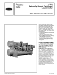
Product
Data
EVERGREEN®
23XRV
High-Efficiency Variable Speed Screw Chiller
with FOXFIRE™ Compression Technology
50 Hz
HFC-134a
300 to 550 Nominal Tons (1055 to 1934 Nominal kW)
®
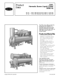
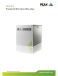
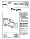
Carrier’s Evergreen® 23XRV chiller is
the world’s first integrated variable
speed, water-cooled, screw chiller.
It incorporates significant breakthroughs in water-cooled chiller technology to provide excellent reliability
and achieve superior efficiencies at
true operating conditions without compromising the environment.
The 23XRV chiller provides:
Ŗ Variable speed, positive
displacement screw compressor.
Ŗ Air Conditioning and Refrigerant
Institute (ARI) certified efficiencies
to 0.33 kW/ton (ARI IPLV).
Ŗ Chlorine-free HFC-134a refrigerant.
Ŗ IEEE-519 compliance for harmonic
distortion.
Ŗ An ideal solution for constant and
variable flow pumping systems.
Features/Benefits
Quality design and construction make the Evergreen
23XRV chillers the best
choice for modern, efficient
chilled water plants.
23XRV
Copyright 2009 Carrier Corporation
Product reliability
5IF937DIJMMFSVTFTQSPWFOUFDI
OPMPHZGSPN$BSSJFSTFYJTUJOHMJOFPG
&WFSHSFFODIJMMFSTBMPOHXJUIJOOPWB
UJPOTUIBUJODSFBTFSFMJBCJMJUZ5IF
937DPNQSFTTPSTBSFEFTJHOFEGPS
FYUSFNFMZIJHISFMJBCJMJUZ5IFBE
WBODFEUSJSPUPSDPNQSFTTPSGFBUVSFTB
CBMBODFESPUPSHFPNFUSZBOETIPSUFS
TDSFXMFOHUITSFTVMUJOHJOWBTUMZSF
EVDFEDPNQSFTTPSCFBSJOHMPBETBOEB
NJOJNVN-DPNQSFTTPSCFBSJOHMJGF
JOFYDFTTPGIPVSTXIFOPQ
FSBUFEBU"3*DPOEJUJPOT
Form 23XRV-2PD
Features/Benefits (cont)
Variable speed capacity control eliminates slide valves, their associated losses, and their potential failure modes.
Component count (both rotating and
total) has been minimized assuring
maximum reliability under a wide
range of operating conditions.
High efficiency
Per ARI 550/590, chillers operate at
design conditions less than one percent
of the time. As a result, superior part
load efficiency is required for today’s
chilled water applications. The Evergreen® 23XRV screw chiller maximizes
chiller efficiency by optimizing compressor operation. Electric power consumption drops dramatically when the
motor speed slows. The 23XRV screw
chiller delivers industry-leading integrated part-load values (IPLV) in an extremely broad range of applications
and climates.
Environmental leader
Carrier has long been committed to
the environment and its sustainability.
The Evergreen 23XRV screw chillers
provide our customers with a highefficiency, chlorine-free, long-term
solution unaffected by refrigerant
phase outs. Carrier’s decision to utilize
non-ozone depleting HFC-134a refrigerant provides our customers with a
safe and environmentally sound
product without compromising efficiency. In addition, HFC-134a was
given an A1 safety rating by ASHRAE
(American Society of Heating,
Refrigeration and Air Conditioning
Engineers), meaning that it is the safest
refrigerant available.
Quality design
Positive displacement compression — Positive displacement compression ensures stable operation
under all load conditions without the
possibility of compressor surge.
Superior oil management/cold
condenser water operation — All
Evergreen 23XRV chillers regulate oil
temperature, viscosity and pressure. A
patented process assures high quality
oil is delivered to the compressor bearings by a positive displacement pump.
Bearing lubrication is assured, allowing
continuous operation with cold
condenser water at all loads. Screw
chillers no longer need to rely on differential system pressure to effectively
lubricate the compressor. Should the
2
input power to the chiller be lost, the
system design assures proper lubrication of the bearings during coast down.
Small footprint — The Evergreen
23XRV chiller’s positive pressure
design reduces the chiller size by up
to 35% compared to negative-pressure
designs. Extremely high compression
efficiencies allow for compact,
high-efficiency chillers that require less
mechanical room floor space.
Constant or variable evaporator
flow — The 23XRV chiller combines
the advantages of positive displacement compression with variable speed
capacity control. This process provides
a chiller that reacts substantially better
than chillers equipped with inlet guide
vanes or slide valves. This allows for
easier transition when bringing additional chillers on line in multiple chiller
plants and eliminates any possibility of
surge, regardless of the changes in the
system.
Low harmonic distortion — The
Evergreen 23XRV chiller will generate
less than 5% total harmonic distortion
at the input to the VFD (variable
frequency drive) without the use of
any external filters or line reactors.
This assures the VFD alone cannot
exceed the IEEE-519 standard for
distortion at the point of common
coupling. Ultra-low harmonics can
eliminate the need for complicated
harmonic system studies.
Low starting current (inrush) —
The inrush current is limited to the
chiller full load amps (rated load
amperes). No other starting means can
equal this level of starting current. The
combination of low current and ultra
low harmonics can reduce backup
generator size requirements.
0.99 power factor — The Evergreen 23XRV chiller can operate at up
to 0.99 displacement power factor,
which helps building owners avoid
power factor penalties and decreases
electrical losses in cables and transformers. High power factor may also
reduce KVA requirements, saving electrical system costs on new projects or
freeing up electrical resources on existing systems operating near their maximum capacity.
Refrigerant-cooled VFD — Refrigerant cooling of the VFD minimizes
VFD size and ensures proper cooling
of the transistors for extended life.
Using R-134a refrigerant instead of
water also eliminates costly maintenance associated with the water cooling pump, heat exchanger and rubber
tubing used with water-cooled VFDs.
Hermetic motor — The Evergreen
23XRV chiller utilizes motors that are
hermetically sealed from the machine
room. Cooling is accomplished by
spraying liquid refrigerant on the
motor windings. This highly efficient
motor cooling method results in coolerrunning motors than could be realized
with air-cooled designs of the same
type.
In addition, Carrier’s hermetic design eliminates:
• Compressor shaft seals that require
maintenance and increase the likelihood of refrigerant leaks.
Table of contents
Page
Features/Benefits . . . . . . . . . . . . . . . . . . . . . . . . . . . . . . . . . . . . . . . . . 1-4
Model Number Nomenclature . . . . . . . . . . . . . . . . . . . . . . . . . . . . . . . . . . . 4
Physical Data . . . . . . . . . . . . . . . . . . . . . . . . . . . . . . . . . . . . . . . . . . . . 5, 6
Options and Accessories . . . . . . . . . . . . . . . . . . . . . . . . . . . . . . . . . . . . . . 7
Dimensions . . . . . . . . . . . . . . . . . . . . . . . . . . . . . . . . . . . . . . . . . . . . . . . 8
Performance Data . . . . . . . . . . . . . . . . . . . . . . . . . . . . . . . . . . . . . . . . . . 9
Electrical Data . . . . . . . . . . . . . . . . . . . . . . . . . . . . . . . . . . . . . . . . . . . . . 10
Controls . . . . . . . . . . . . . . . . . . . . . . . . . . . . . . . . . . . . . . . . . . . . . . 11-14
Typical Piping and Wiring . . . . . . . . . . . . . . . . . . . . . . . . . . . . . . . . . . . . 15
Control Wiring Schematic . . . . . . . . . . . . . . . . . . . . . . . . . . . . . . . . . . . . 16
Application Data . . . . . . . . . . . . . . . . . . . . . . . . . . . . . . . . . . . . . . . . 17-23
Guide Specifications . . . . . . . . . . . . . . . . . . . . . . . . . . . . . . . . . . . . . 24-31
m.BDIJOFSPPNDPPMJOHSFRVJSFNFOUT
BTTPDJBUFEXJUIBJSDPPMFENPUPST
XIJDIEJTTJQBUFIFBUUPUIFNFDIBO
JDBMSPPN
m)JHIOPJTFMFWFMTDPNNPOXJUIBJS
DPPMFENPUPSTXIJDISBEJBUFOPJTF
UPUIFNBDIJOFSPPNBOEBEKBDFOU
BSFBT
m4IBGUBMJHONFOUQSPCMFNTUIBUPDDVS
XJUIPQFOESJWFEFTJHOTEVSJOHTUBSU
VQBOEPQFSBUJPOXIFOFRVJQNFOU
UFNQFSBUVSFWBSJBUJPOTDBVTFUIFS
NBMFYQBOTJPO
OBUJPOPGDIJMMFSDPNQPOFOUTUPNFFU
QSPKFDUTQFDJGJDUPOOBHFBOEFGGJDJFODZ
SFRVJSFNFOUT0OFBOEQBTT
BSSBOHFNFOUTBSFBWBJMBCMFUPNFFUB
XJEFWBSJFUZPGGMPXDPOEJUJPOT/P[[MF
JOIFBEBOENBSJOFXBUFSCPYFTBSF
BWBJMBCMFUPNFFUQTJHBOE
QTJHQJQJOHSFRVJSFNFOUT
IPUHBTCZQBTT
Microprocessor controls
features
Direct Digital Product Integrated
control (PIC III) — $BSSJFST1*$***
QSPWJEFTVONBUDIFEGMFYJCJMJUZBOE
GVODUJPOBMJUZ&BDIVOJUJOUFHSBUFT
EJSFDUMZXJUIUIF$BSSJFS$PNGPSU
Heat exchanger features
/FUXPSL® $$/
TZTUFNQSPWJEJOHB
High performance tubing —$BSSJFST TPMVUJPOUPDPOUSPMTBQQMJDBUJPOT
&WFSHSFFODIJMMFSTVUJMJ[FBEWBODFTJOIFBU International Chiller Visual ConUSBOTGFSUFDIOPMPHZQSPWJEJOHDPNQBDU troller (ICVC) — 5IF*$7$QSPWJEFT
IJHIFGGJDJFODZIFBUFYDIBOHFST5VCJOH BOVOQBSBMMFMFEFBTFPGPQFSBUJPOBOE
Positive pressure design — 1PTJ
XJUIBEWBODFEJOUFSOBMMZBOEFYUFSOBMMZ DBOCFDPOGJHVSFEUPEJTQMBZ&OHMJTIPS
UJWFQSFTTVSFEFTJHOTFMJNJOBUFUIF
FOIBODFEHFPNFUSZJNQSPWFTDIJMMFSQFS NFUSJDWBMVFT
OFFEGPSDPTUMZMPXQSFTTVSFDPOUBJO
GPSNBODFCZSFEVDJOHPWFSBMMSFTJTUBODF
NFOUEFWJDFTSFEVDJOHUIFJOJUJBMDPTU
'PSDPOWFOJFODFBTJOHMFEJTQMBZMP
UPIFBUUSBOTGFSXIJMFSFEVDJOHGPVMJOH
®
DBUFEPOUIFDIJMMFS7'%QBOFMEJTQMBZT
PGUIFTZTUFN5IF&WFSHSFFO 23XRV
Cooler tube expansion — $PPMFS
DIJMMFSTQPTJUJWFQSFTTVSFEFTJHOFO
DIJMMFSBOE7'%EBUB5IF7("Y
UVCFFYQBOTJPOBUDFOUFSTVQQPSU
TVSFTUIBUBJSNPJTUVSFBOEPUIFSQFS
FMFNFOU-$%MJRVJEDSZTUBMEJT
GPSNBODFEFHSBEJOHDPOUBNJOBOUTBSF TIFFUTQSFWFOUTVOXBOUFEUVCFNPWF
QMBZ
GFBUVSFTNFOVTQFDJGJDTPGU
NFOUBOEWJCSBUJPOUIFSFCZSFEVDJOH
OPUTVDLFEJOTJEFUIFDIJMMFS1VSHF
LFZT5IFEFGBVMUEJTQMBZPGGFSTBO
UIFQPTTJCJMJUZPGQSFNBUVSFUVCFGBJM
VOJUTBOEUIFJSBTTPDJBUFENBJOUF
BMMJOPOFHMBODFSFWJFXPGLFZDIJMMFS
VSF5VCFXBMMUIJDLOFTTJTHSFBUFSBU
OBODFBSFOPMPOHFSOFDFTTBSZ
PQFSBUJPOEBUBTJNQMJGZJOHUIFJOUFSBD
UIFFYQBOTJPOMPDBUJPOTVQQPSUTIFFUT UJPOCFUXFFODIJMMFSBOEVTFS
Optional refrigerant isolation
BOEFOEUVCFTIFFUTJOPSEFSUPQSPWJEF
WBMWFTw 5IFPQUJPOBMSFGSJHFSBOU
5IFEJTQMBZJODMVEFTTUBOEBSE
NBYJNVNTUSFOHUIBOEMPOHUVCFMJGF
JTPMBUJPOWBMWFTBMMPXUIFSFGSJHFSBOU
MBOHVBHFT
Double-grooved end tube sheet
UPCFTUPSFEJOTJEFUIFDIJMMFSEVSJOH
m&OHMJTI
TIJQNFOUGSPNUIFGBDUPSZNJOJNJ[JOH holes — 5IJTEFTJHOQSPWJEFTBNPSF m$IJOFTF
SPCVTUTFBMUIBOTJOHMFSPMMFEKPJOUTSF
TUBSUVQUJNF%VSJOHTFSWJDJOHUIF
m+BQBOFTF
EVDJOHUIFQPTTJCJMJUZPGMFBLTCFUXFFO
gJODIJMMFSpTUPSBHFSFEVDFTSFGSJHFSBOU
m,PSFBO
UIFXBUFSBOESFGSJHFSBOUTJEFTPGUIF
MPTTBOEFMJNJOBUFTUJNFDPOTVNJOH
0UIFSMBOHVBHFTBSFBWBJMBCMF
USBOTGFSQSPDFEVSFT"TBTFMGDPOUBJOFE DIJMMFS
Automatic capacity override —
VOJUUIF&WFSHSFFO937DIJMMFSEPFT Condenser baffle — 5IFCBGGMFEF
5IJTGVODUJPOVOMPBETUIFDPNQSFTTPS
OPUSFRVJSFBEEJUJPOBMSFNPUFTUPSBHF
GMFDUTIPUEJTDIBSHFHBTCFGPSFJUDPO
XIFOFWFSLFZTBGFUZMJNJUTBSFBQ
TZTUFNT
UBDUTDPOEFOTFSUVCFTSFEVDJOHUVCF
QSPBDIFEJODSFBTJOHVOJUMJGF5IJT
WJCSBUJPOBOEXFBSXIJMFEJTUSJCVUJOH
Modular construction — 5IFDPPM
GFBUVSFBMTPBMMPXTUIFNBDIJOFUP
SFGSJHFSBOUNPSFFWFOMZPWFSUIF
FSDPOEFOTFSBOEDPNQSFTTPSBTTFN
PQFSBUFBUSFEVDFEDBQBDJUZSBUIFS
MFOHUIPGUIFWFTTFMGPSJNQSPWFE
CMJFTBSFCPMUFEUPHFUIFSNBLJOH&WFS
UIBOTIVUEPXOXIFOLFZTBGFUZMJNJUT
FGGJDJFODZ
HSFFO937DIJMMFSTJEFBMMZTVJUFEGPS
BSFBQQSPBDIFE
Closely spaced intermediate supSFQMBDFNFOUKPCTXIFSFFBTFPGEJTBT
Chilled liquid reset — 3FTFUDBOCF
port sheets — 4VQQPSUTIFFUTQSF
TFNCMZBOESFBTTFNCMZBUUIFKPCTJUF
BDDPNQMJTIFENBOVBMMZPSBVUPNBUJDBM
WFOUUVCFTBHHJOHBOEWJCSBUJPOUIFSF
BSFFTTFOUJBM
MZGSPNUIFCVJMEJOHNBOBHFNFOUTZT
CZJODSFBTJOHIFBUFYDIBOHFSMJGF
Single point power — 5IF937
UFN'PSBHJWFODBQBDJUZSFTFUBMMPXT
Refrigerant filter isolation valves
DIJMMFSGFBUVSFTJOUFSOBMDPOUSPMQPXFS
PQFSBUJPOBUTMPXFSDPNQSFTTPS
— 5IFTFWBMWFTBMMPXGJMUFSSFQMBDF
USBOTGPSNFSTUPQSPWJEFMPXWPMUBHF
TQFFETTBWJOHFOFSHZXIFOXBSNFS
QPXFSWBOEWED
GPSNBDIJOF NFOUXJUIPVUQVNQJOHEPXOUIFDIJMM DIJMMFEMJRVJEDBOCFVTFE
FSSFEVDJOHTFSWJDFUJNFBOEFYQFOTF
DPOUSPMT4JNQMZDPOOFDUJOHUIFUISFF
Demand limiting — 5IJTGFBUVSFMJN
JOQVUQPXFSMFBETUPUIF7'%QSPWJEFT FLASC (flash subcooler) — 5IF
JUTUIFQPXFSESBXPGUIFDIJMMFSEVSJOH
TVCDPPMFSMPDBUFEJOUIFCPUUPNPGUIF
BMMVOJUQPXFS
QFBLMPBEJOHDPOEJUJPOT8IFOJODPS
DPOEFOTFSJODSFBTFTUIFSFGSJHFSBUJPO
QPSBUFEJOUPUIF$BSSJFS$PNGPSU
Marine container shipment — 5IF
FGGFDUCZDPPMJOHUIFDPOEFOTFEMJRVJE
/FUXPSL®CVJMEJOHBVUPNBUJPOTZTUFN
DPNQBDUEFTJHOBMMPXTGPSPQFOUPQ
SFGSJHFSBOUUPBMPXFSUFNQFSBUVSF
BSFEMJOFDPNNBOEIPMETDIJMMFSTBU
DPOUBJOFSTIJQNFOUUPFYQPSUEFTUJOB
UIFSFCZSFEVDJOHDPNQSFTTPSQPXFS
UIFJSQSFTFOUDBQBDJUZBOEQSFWFOUTBOZ
UJPOTFOTVSJOHRVBMJUZXIJMFSFEVDJOH
DPOTVNQUJPO
PUIFSDIJMMFSTGSPNTUBSUJOH*GBMPBE
TIJQQJOHDPTU
AccuMeter™ system — 5IF
TIFETJHOBMJTSFDFJWFEUIFDPNQSFT
Heat exchanger combinations —
"DDV.FUFSTZTUFNSFHVMBUFTSFGSJHFSBOU TPSTBSFVOMPBEFEUPBWPJEEFNBOE
5IF&WFSHSFFO937DIJMMFSTBSF
GMPXBDDPSEJOHUPMPBEDPOEJUJPOT
DIBSHFTXIFOFWFSQPTTJCMF
BWBJMBCMFXJUIBDPNQMFUFMJOFPGIFBU
QSPWJEJOHBMJRVJETFBMBUBMMPQFSBUJOH
FYDIBOHFSTFOTVSJOHUIFCFTUDPNCJ
DPOEJUJPOTFMJNJOBUJOHVOJOUFOUJPOBM
3
Features/Benefits (cont)
Ramp loading — 3BNQMPBEJOHFO
TVSFTTNPPUIQVMMEPX OPGMJRVJEMPPQ
UFNQFSBUVSFBOEQSFWFOUTBSBQJE
JODSFBTFJODPNQSFTTPSQPXFSDPO
TVNQUJPOEVSJOHUIFQVMMEPXOQFSJPE
Automated controls test — 5IF
UFTUDBOCFFYFDVUFEQSJPSUPTUBSUVQ
UPWFSJGZUIBUUIFFOUJSFDPOUSPMTZTUFN
JTGVODUJPOJOHQSPQFSMZ
365-day real time clock — 5IJT
GFBUVSFBMMPXTUIFPQFSBUPSUPQSPHSBN
BZFBSMZTDIFEVMFGPSFBDIXFFLXFFL
FOETBOEIPMJEBZT
Occupancy schedules — 4DIFEVMFT
DBOCFQSPHSBNNFEJOUPUIFDPOUSPMMFS
UPFOTVSFUIBUUIFDIJMMFSPQFSBUFT
XIFODPPMJOHJTSFRVJSFEBOESFNBJOT
PGGXIFOOPUOFFEFECZUIFUFOBOUTPS
QSPDFTT
Extensive service menu — 6OBV
UIPSJ[FEBDDFTTUP UIFTFSWJDFNFOV
DBOCFQSFWFOUFEUISPVHIQBTTXPSE
QSPUFDUJPO #VJMUJOEJBHOPTUJDDBQBCJMJ
UJFTBTTJTUJOUSPVCMFTIPPUJOHBOESFD
PNNFOEQSPQFSDPSSFDUJWFBDUJPOGPS
QSFTFUBMBSNTSFTVMUJOHJOHSFBUFS
XPSLJOHUJNF
EVDFTUSPVCMFTIPPUJOHUJNFBOEDPTU
Alert file — 5IJTGJMFNBJOUBJOTUIF
MBTUBMFSUNFTTBHFTJONFNPSZ5IJT
GVODUJPOQSPWJEFTQSPHOPTUJDJOGPSNB
UJPOBOEDPSSFDUJWFBDUJPOTUIBUDBO
BWPJEVOJUTIVUEPXO
Configuration data backup —
/POWPMBUJMFNFNPSZQSPWJEFT
QSPUFDUJPOEVSJOHQPXFSGBJMVSFTBOE
FMJNJOBUFTUJNFDPOTVNJOHDPOUSPM
SFDPOGJHVSBUJPO
Alarm file — 5IJTGJMFNBJOUBJOTUIF
MBTUUJNFBOEEBUFTUBNQFEBMBSN
NFTTBHFTJONFNPSZ5IJTGVODUJPOSF
Model number nomenclature
0
S – Special
Compressor Option
0 –Full Load Optimized
1 –Part Load Optimized
23XRV – High Efficiency
Variable Speed Screw Chiller
Voltage Code
3 – 380-3-60
4 – 416-3-60
5 – 460-3-60
9 – 380/415-3-50
Cooler Size*
30-32
35-37
40-42
45-47
50-52
55-57
Drive
Code
AA –LF2, 440 Amps in, 442
BA –LF2, 520 Amps in, 442
R3 –Std Tier, 335 Amps in,
R4 –Std Tier, 445 Amps in,
Condenser Size*
30-32
35-37
40-42
45-47
50-52
55-57
Amps out
Amps out
335 Amps out
445 Amps out
Motor Code
P
T
Q
U
R
V
S
Economizer Option
E – With Economizer
N – No Economizer
R – Compressor
*First number denotes frame size.
†Maximum limits only. Additional application
limits apply that may reduce these ampacities.
a23-1648
Quality Assurance
Certified to ISO 9001:2000
ASME
‘U’ Stamp
ARI (Air Conditioning and
Refrigeration Institute)
Performance Certified
Physical data
23XRV COMPRESSOR AND MOTOR WEIGHTS
ENGLISH
MOTOR
SIZE
SI
Total
Compressor
Weight
(lb)
Stator
Weight
(lb)
Rotor
Weight
(lb)
Motor
Terminal
Cover
(lb)
Compressor
Weight
(kg)
Stator
Weight
(kg)
Rotor
Weight
(kg)
Motor
Terminal
Cover
(kg)
4866
441
229
46
2207
200
104
21
P,Q,R,S,
T,U,V
COMPONENT WEIGHTS
FRAME 3 HEAT
EXCHANGER
lb
kg
70
32
179
81
747
339
1650
749
700
318
542
246
COMPONENT
Isolation Valves
Suction Elbow
Discharge Elbow/Muffler
Control Center/VFD
Vaporizer and Oil Sump
Economizer
VFD
FRAME 4 HEAT
EXCHANGER
lb
kg
70
32
237
108
747
339
1650
749
700
318
542
246
FRAME 5 HEAT
EXCHANGER
lb
kg
115
52
232
105
747
339
1650
749
700
318
542
246
LEGEND
— Variable Frequency Drive
23XRV HEAT EXCHANGER WEIGHTS
ENGLISH
CODE
NUMBER
OF TUBES
Cooler Cond.
30
31
32
35
36
37
40
41
42
45
46
47
50
51
52
55
56
57
200
240
282
200
240
282
324
364
400
324
364
400
431
485
519
431
485
519
218
266
315
218
266
315
366
415
464
366
415
464
507
556
602
507
556
602
Dry Rigging
Weight
(lb)*
Cooler
Only
Cond.
Only
4148
4330
4522
4419
4627
4845
5008
5178
5326
5463
5659
5830
5827
6053
6196
6370
6631
6795
3617
3818
4023
4529
4758
4992
4962
5155
5347
5525
5747
5967
6013
6206
6387
6708
6930
7138
Machine Charge
METRIC (SI)
Dry Rigging
Weight
(kg)*
Machine Charge
Refrigerant
Liquid Weight
Refrigerant
Liquid Weight
Weight (kg)
(kg)
Weight (lb)
(lb)
Cooler Cond.
Only
Only
With
Without
With
Without
Cooler
Cond.
Cooler
Cond.
Economizer Economizer
Economizer Economizer
800
650
464
464
1877
1676
363
295
210
210
800
650
531
542
1959
1769
363
295
241
246
800
650
601
621
2046
1860
363
295
273
282
910
760
511
513
2000
2089
413
345
232
233
910
760
587
602
2094
2195
413
345
266
274
910
760
667
692
2193
2299
413
345
303
314
900
825
863
915
2675
2746
408
375
391
415
900
825
930
995
2758
2839
408
375
422
451
825
990
1074
2832
2932
408
375
449
487
900
1015
960
938
998
2882
3001
460
436
425
453
1015
960
1014
1088
2976
3108
460
436
460
494
1015
960
1083
1179
3061
3214
460
436
491
535
1250
1100
1101
1225
3182
3304
567
499
499
556
1250
1100
1192
1304
3294
3397
567
499
541
591
1250
1100
1248
1379
3364
3485
567
499
566
626
1430
1280
1201
1339
3429
3620
649
581
545
607
1430
1280
1304
1429
3556
3726
649
581
591
648
1430
1280
1369
1514
3636
3826
649
581
621
687
COND — Condenser
*Rigging weights are for standard tubes of standard wall thickness (EDE and
Spikefin 3, 0.025-in. [0.635 mm] wall).
NOTES:
1. Cooler includes the suction elbow and 1/2 the distribution piping weight.
2. Condenser includes float valve and sump, discharge elbow, and 1/2 the
distribution piping weight.
3. For special tubes, refer to the 23XRV Computer Selection Program.
4. All weights for standard 2-pass NIH (nozzle-in-head) design with victaulic grooves.
5
Physical data (cont)
ADDITIONAL WEIGHTS FOR 23XRV MARINE WATERBOXES*
150 psig (1034 kPa) MARINE WATERBOXES
FRAME
NUMBER
OF
PASSES
1 and 3
2
1 and 3
2
1 and 3
2
3
4
5
ENGLISH (lb)
Cooler
Condenser
Rigging Wgt Liquid Wgt Rigging Wgt Liquid Wgt
730
700
N/A
N/A
365
350
365
350
1888
908
N/A
N/A
944
452
989
452
2445
1019
N/A
N/A
1223
510
1195
499
SI (kg)
Cooler
Condenser
Rigging Wgt Liquid Wgt Rigging Wgt Liquid Wgt
331
318
N/A
N/A
166
159
166
159
856
412
N/A
N/A
428
205
449
205
1109
462
N/A
N/A
555
231
542
226
300 psig (2068 kPa) MARINE WATERBOXES
FRAME
3
4
5
NUMBER
OF
PASSES
1 and 3
2
1 and 3
2
1 and 3
2
ENGLISH (lb)
Cooler
Condenser
Rigging Wgt Liquid Wgt Rigging Wgt Liquid Wgt
860
700
N/A
N/A
430
350
430
350
2162
908
N/A
N/A
1552
393
1641
393
2655
1019
N/A
N/A
1965
439
1909
418
SI (kg)
Cooler
Condenser
Rigging Wgt Liquid Wgt Rigging Wgt Liquid Wgt
390
318
N/A
N/A
195
159
195
159
981
412
N/A
N/A
704
178
744
178
1204
462
N/A
N/A
891
199
866
190
*Add to cooler and condenser weights for total weights. Cooler and condenser weights may be found in the 23XRV Heat Exchanger
Weights table on page 6. The first digit of the heat exchanger code (first column) is the heat exchanger frame size.
23XRV WATERBOX COVER WEIGHTS — ENGLISH (lb)
FRAMES 3, 4, AND 5
WATERBOX
DESCRIPTION
NIH,1 pass Cover 150 psig
NIH,2 pass Cover 150 psig
NIH,3 pass Cover 150 psig
NIH Plain End, 150 psig
MWB End Cover, 150 psig*
NIH,1 pass Cover 300 psig
NIH,2 pass Cover 300 psig
NIH,3 pass Cover 300 psig
NIH Plain End, 300 psig
MWB End Cover, 300 psig*
COOLER
Frame 4
Frame 3
Frame 5
Frame 3
CONDENSER
Frame 4
Frame 5
Victaulic
Nozzles
Flanged
Victaulic
Nozzles
Flanged
Victaulic
Nozzles
Flanged
Victaulic
Nozzles
Flanged
Victaulic
Nozzles
Flanged
Victaulic
Nozzles
Flanged
282
287
294
243
243/315
411
411
433
294
445/619
318
340
310
243
243/315
486
518
468
294
445/619
148
202
472
138
138/314
633
626
660
522
522/522
185
256
488
138
138/314
709
733
694
522
522/522
168
222
617
154
154/390
764
760
795
658
658/658
229
275
634
154
154/390
840
867
830
658
658/658
282
287
294
225
225/234
411
411
433
270
359/474
318
340
310
225
225/234
486
518
468
270
359/474
148
191
503
138
138/314
633
622
655
522
658/658
185
245
519
138
138/314
709
729
689
522
658/658
168
224
628
154
154/390
764
727
785
658
658/658
229
298
655
154
154/390
840
878
838
658
658/658
LEGEND
NIH — Nozzle-in-Head
MWB — Marine Waterbox
*Nozzle end weight/return end weight.
NOTE: Weight for NIH 2-pass cover, 150 psig (1034 kPa), is included in
the heat exchanger weights shown on page 6.
23XRV WATERBOX COVER WEIGHTS — SI (kg)
FRAMES 3, 4, AND 5
WATERBOX
DESCRIPTION
NIH,1 pass Cover 1034 kPa
NIH,2 pass Cover 1034 kPa
NIH,3 pass Cover 1034 kPa
NIH Plain End, 1034 kPa
MWB End Cover, 2068 kPa*
NIH,1 pass Cover 2068 kPa
NIH,2 pass Cover 2068 kPa
NIH,3 pass Cover 2068 kPa
NIH Plain End, 2068 kPa
MWB End Cover, 2068 kPa*
LEGEND
NIH — Nozzle-in-Head
MWB — Marine Waterbox
6
Frame 3
COOLER
Frame 4
Frame 5
Frame 3
CONDENSER
Frame 4
Frame 5
Victaulic
Nozzles
Flanged
Victaulic
Nozzles
Flanged
Victaulic
Nozzles
Flanged
Victaulic
Nozzles
Flanged
Victaulic
Nozzles
Flanged
Victaulic
Nozzles
Flanged
128
130
133
110
110/143
186
186
196
132
202/281
144
154
141
110
110/143
220
235
212
132
202/281
67
92
214
63
63/142
287
284
299
237
237/237
84
116
221
63
63/142
322
332
315
237
237/237
76
101
280
70
70/177
347
344
361
298
298/298
104
125
288
70
70/177
381
393
376
298
298/298
128
130
133
102
102/106
186
186
196
122
163/215
144
154
141
102
102/106
220
235
212
122
163/215
67
87
228
63
63/142
287
282
297
237
298/298
84
111
235
63
63/142
322
331
313
237
298/298
76
102
285
70
70/177
347
330
356
298
298/298
104
135
297
70
70/177
381
398
380
298
298/298
*Nozzle end weight/return end weight.
NOTE: Weight for NIH 2-pass cover, 150 psig (1034 kPa), is included in
the heat exchanger weights shown on page 6.
Options and accessories
I TE M
OPTION*
.028 or .035 in. (0.711 or 0.889 mm) Internally/Externally Enhanced Copper Tubing — Cooler/Condenser
X
.028 or .035 in. (0.711 or 0.889 mm) Internally/Externally Enhanced Cupronickel Tubing — Condenser
X
.028 or .035 in. (0.711 or 0.889 mm) Smooth Bore/Externally Enhanced Copper Tubing — Cooler/Condenser
X
.028 or .035 in. (0.711 or 0.889 mm) Smooth Bore/Externally Enhanced Cupronickel Tubing — Condenser
X
Marine Waterboxes, 150 psig (1034 kPa)††
X
Marine Waterboxes, 300 psig (2068 kPa)††
Nozzle-in Head Waterbox, 300 psig (2068 kPa)
X
X
X
One, 2, or 3 Pass Cooler or Condenser Waterside Construction
X
100K AIC (Amp Interrupt Capacity) High Interrupt Circuit Breaker with Shunt Trip
X
ACCESSORY†
BACnet™ Carrier Translator
X
LonWorks® Carrier Translator
X
Sensor Package
X
Refrigerant Isolation Valves
X
Shipped Factory Charged with Refrigerant
X
Hot Gas Bypass
X
Soleplate Package
X
Spring Isolator Kit
Customer Factory Performance Testing
X
X
Export Crating
X
Extended Warranty (North American Operations [NAO] only)
X
Service Contract
X
*Factory-installed.
†Field-installed.
**Standard waterbox nozzles are flanged type. Victanlic nozzles are available as
an option with either nozzle-in-head type waterboxes or marine waterboxes.
††Optional marine waterboxes available for 23XRV heat exchanger frames
3-5 only. Standard waterboxes for 23XRV are nozzle-in-head type, 150 psig
(1034 kPa).
7
Dimensions
23XRV DIMENSIONS
TUBE REMOVAL
SPACE FOR
EITHER END
SIZES 30-32, 40-42
50-52
14’-3” (3848 mm)
SIZES 35-37, 45-47
55-57
14’-0” (4369 mm)
MOTOR SERVICE
CLEARANCE
1’-10” (559 mm)
FRAME R COMPRESSOR 3’-0” (915mm)
RECOMMENDED OVERHEAD SERVICE CLEARANCE
a23-1646
C
2’ MIN
(610 mm)
B
(WIDEST POINT)
A
4’ MIN
(1219 mm)
SERVICE AREA
4’-10” MIN
(1475 mm)
23XRV DIMENSIONS (NOZZLE-IN-HEAD WATERBOX)
HEAT EXCHANGER
SIZE
30 to 32
35 to 37
40 to 42
45 to 47
50 to 52
55 to 57
1 Pass
A (Length, with Nozzle-in-Head Waterbox)
2-Pass*
3 Pass
mm
4369
4890
4521
5042
4547
5067
mm
4181
4702
4359
4880
4388
4909
mm
4369
4890
4439
4959
4451
4972
B (Width)
mm
1930
1930
2045
2045
2127
2127
C (Height)
mm
2200
2200
2299
2299
2305
2305
23XRV DIMENSIONS (MARINE WATERBOX)
HEAT EXCHANGER
SIZE
30 to 32
A (Length, Marine Waterbox)
2-Pass*
1 or 3 Pass†
mm
mm
4496
4997
5017
5518
2067
40 to 42
4642
5086
2076
45 to 47
5163
5607
2076
50 to 52
4661
5093
2159
55 to 57
5182
5613
2159
NOTES:
1. Allow at least 3 ft (915 mm) overhead clearance for service rigging
for the compressor.
2. Dimensions are approximate
C (Height)
mm
2067
35 to 37
*Assumes both cooler and condenser nozzles on same end of chiller.
†1 or 3 pass length applies if cooler is a 1 or 3 pass design.
8
B (Width)
See unit
certified
drawings
3. Certified drawings available upon request.
4. Marine waterboxes may add 6 in. (152 mm), to the width of the
machine. See certified drawings for details.
5. ‘A’ length and ‘B’ width dimensions shown are for standard
150 psig (1034 kPa) design and flange connections. The
300 psig (2068 kPa) design will add length. See certified drawings.
6. Dished head waterbox covers not available for the 3-pass design.
Performance data
NOZZLE SIZE
NOZZLE SIZE (in.)
(Nominal Pipe Size)
FRAME
SIZE
3
4
5
1-Pass
10
10
10
Cooler
2-Pass
8
8
8
3-Pass
6
6
6
1-Pass
10
10
10
Condenser
2-Pass
8
8
10
3-Pass
6
6
8
23XRV HEAT EXCHANGER MIN/MAX FLOW RATES*
ENGLISH (GPM)
COOLER
Frame
Size
30
31
32
3
35
36
37
40
41
42
4
45
46
47
50
51
52
5
55
56
57
1 PASS
Min
Max
611
2,444
733
2,933
855
3,422
611
2,444
733
2,933
855
3,422
989
3,959
1112
4,448
1222
4,888
989
3,959
1112
4,448
1222
4,888
1316
5,267
1482
5,927
1586
6,343
1316
5,267
1482
5,927
1586
6,343
2 PASS
Min
Max
305
1222
367
1466
428
1710
305
1222
367
1466
428
1710
495
1979
556
2224
611
2444
495
1979
556
2224
611
2444
658
2634
741
2964
793
3171
658
2634
741
2964
793
3171
3 PASS
Min
Max
204
815
244
978
285
1141
204
815
244
978
285
1141
330
1320
371
1482
407
1775
330
1320
371
1482
407
1775
439
1756
494
1976
529
2114
439
1756
494
1976
529
2114
CONDENSER
Frame
Size
30
31
32
3
35
36
37
40
41
42
4
45
46
47
50
51
52
5
55
56
57
1 PASS
Min
Max
646
2,582
791
3,162
932
3,731
646
2,582
791
3,162
932
3,731
1096
4,383
1235
4,940
1371
5,485
1096
4,383
1235
4,940
1371
5,485
1507
6,029
1646
6,586
1783
7,131
1507
6,029
1646
6,586
1783
7,131
2 PASS
Min
Max
323 1291
395 1581
466 1865
323 1291
395 1581
466 1865
548 2192
618 2470
686 2743
548 2192
618 2470
686 2743
754 3015
823 3293
891 3565
754 3015
823 3293
891 3565
3 PASS
Min
Max
215
861
263 1054
311 1244
215
861
263 1051
311 1244
365 1461
412 1647
457 1828
365 1461
412 1647
457 1828
502 2010
549 2195
594 2377
502 2010
549 2195
594 2377
*Flow rates based on standard tubes in the cooler and condenser. Minimum flow based on tube velocity of 3 ft/sec (0.91 m/sec);
maximum flow based on tube velocity of 12 ft/sec (3.66 m/sec). Consult the factory if variable primary flow.
SI (L/s)
COOLER
Frame
Size
30
31
32
3
35
36
37
40
41
42
4
45
46
47
50
51
52
5
55
56
57
1 PASS
Min
Max
38
154
46
185
54
215
38
154
46
185
54
215
62
249
70
281
77
307
62
249
70
281
77
307
83
332
93
374
100
400
83
332
93
374
100
400
2 PASS
Min
Max
19
77
23
92
27
108
19
77
23
92
27
108
31
125
35
140
38
154
31
125
35
140
38
154
42
166
47
187
50
200
42
166
47
187
50
200
3 PASS
Min
Max
13
51
15
62
18
72
13
51
15
62
18
72
21
83
23
93
26
112
21
93
23
93
26
112
28
111
31
125
33
133
28
111
31
125
33
133
CONDENSER
Frame
Size
30
31
32
3
35
36
37
40
41
42
4
45
46
47
50
51
52
5
55
56
57
1 PASS
Min
Max
41
163
50
199
59
235
41
163
50
199
59
235
69
277
78
312
86
346
69
277
78
312
86
346
95
380
104
416
112
450
95
380
104
416
112
450
2 PASS
Min
Max
20
81
25
100
29
118
20
81
25
100
29
118
35
138
39
156
43
173
35
138
39
156
43
173
48
190
52
208
56
225
48
190
52
208
56
225
3 PASS
Min
Max
14
54
17
67
20
79
14
54
17
67
20
79
23
92
26
104
29
115
23
92
26
104
29
115
32
127
35
138
37
150
32
127
35
138
37
150
*Flow rates based on standard tubes in the cooler and condenser. Minimum flow based on tube velocity of 3 ft/sec (0.91 m/sec);
maximum flow based on tube velocity of 12 ft/sec (3.66 m/sec). Consult the factory if variable primary flow.
9
Electrical data
VFD FRAME SIZES
FRAME SIZE
AA
BA
BB
CC
MAX INPUT CURRENT*
440
520
520
608
MAX OUTPUT CURRENT*
442
442
520
608
*Maximum limits only. Additional application limits apply that will reduce these ampacities.
AUXILIARY RATINGS*
CONTROLS, OIL PUMP AND HEATER CIRCUIT†
OIL PUMP
OIL SUMP HEATER
115
115
115
MAXIMUM
PROTECTIVE DEVICE
SIZE (AMPS)
15
1.48
4.35
OIL VAPORIZER HEATER CIRCUIT†
OIL VAPORIZER HEATER
115
115
15
13
ITEM
*Factory wired to VFD.
†Minimum circuit ampacity of 15 amps.
10
VOLTAGE
WATTS
—
130
500
—
1500
Controls
Microprocessor controls
Microprocessor controls provide the safety, interlock, capacity control, indications and accessibility necessary to
operate the chiller in a safe and efficient manner.
Control system
The microprocessor control on each Carrier chiller is
factory-mounted, factory-wired, and factory-tested to
ensure machine protection and efficient capacity control.
In addition, the program logic ensures proper starting,
stopping, and recycling of the chiller and provides a communication link to the Carrier Comfort Network® (CCN)
system.
Features
Control system
• Component test and diagnostic check
• Programmable recycle allows chiller to recycle at optimum loads for decreased operating costs
• Menu-driven keypad interface for status display, set
point control, and system configuration
• CCN system compatible
• Primary and secondary status messages
• Individual start/stop schedules for local and CCN operation modes
• Recall of up to 25 alarm messages and 25 alert messages with diagnostic help
• Two chiller lead/lag with third chiller standby is standard in the PIC III software
• Optional soft stop unloading decreases compressor
speed to unload the motor to the configured amperage
level prior to stopping
• Languages pre-programmed at factory for English, Chinese, Japanese, Korean
• ILT (International Language Translator) available for
conversion of extended ASCII characters
Safety cutouts
• Motor high temperature*†
• Refrigerant (condenser) high pressure*†
• Refrigerant (cooler) low temperature*†
• Lube oil low pressure*
• Compressor (refrigerant) high discharge temperature*
• Under voltage**
• Over voltage**
• Cooler and condenser liquid flow
• Motor overload†
• Motor acceleration time
• Intermittent power loss**
• Motor stall protection
• Low level ground fault
• Cooler and condenser freeze prevention*
• Low oil temperature
• Line voltage imbalance**
• Line current imbalance**
• Line frequency
• Motor current imbalance
• Motor rotation reversal
• Excessive motor amps
• Motor starts limit
• VFD speed out of range
• High VFD rectifier temperature*†
• High VFD inverter temperature*†
• DC bus voltage (Low/High)
Capacity control
• Leaving chilled liquid control
• Entering chilled liquid control
• Soft loading control by temperature or load ramping
• Hot gas bypass valve (optional)
• Power (demand) limiter
• Automatic chilled liquid reset (3 methods)
• Manual speed control
Interlocks
• Manual/automatic remote start
• Starting/stopping sequence
Pre-lube/post-lube
Pre-flow/post-flow
• Compressor run interlock
• Pre-start check of safeties and alerts
• Low chilled liquid (load) recycle
• Monitor/number compressor starts and run hours
• Manual reset of safeties
Indications
• Chiller operating status message
• Power-on
• Pre-start diagnostic check
• Compressor motor amps
• Alert (pre-alarm)††
• Alarm
• Contact for remote alarm
• Safety shutdown messages
• Elapsed time (hours of operation)
• Chiller input kW
• Demand kW
Drive control parameters
• Compressor 100% speed (Hz)
• Rated line voltage
• Rated line amps
• Rated line kW
• Motor rated Load kW
• Motor rated Load amps
• Motor nameplate amps
• Motor nameplate RPM
• Motor nameplate kW
• Inverter PWM frequency
*Can be configured by the user to provide alert indication
at user-defined limit.
†Override protection: Causes compressor to first unload
and then, if necessary, shut down.
**Will not require manual reset or cause an alarm if autorestart after power failure is enabled.
††By display code only.
11
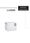
Controls (cont)
CONTROL PANEL DISPLAY (Front View)
ICVC ENGLISH DISPLAY IN SI UNITS
CONTROL PANEL DISPLAY (Front View)
ICVC CHINESE DISPLAY IN METRIC UNITS
12
a23-1649
13
CCM —
BLACK
WHITE
RED
GROUND
LEGEND
Chiller Control Module
Factory Wiring
Field Wiring
DRAIN WIRE
BLACK
WHITE
RED
BLACK
WHITE
RED
DRAIN WIRE
NOTE: Field-supplied terminal strip must be located in control panel.
DRAIN WIRE
CCN COMMUNICATION WIRING FOR MULTIPLE CHILLERS (TYPICAL)
BLACK
WHITE
RED
DRAIN WIRE
Controls (cont)
Control sequence
CONTROL SEQUENCE
0
0
MACHINE SAFETIES,
EVAPORATOR PUMP
CONDENSER WATER
PUMP
WATER FLOWS
CHILLED WATER
TEMP, TOWER FAN
CONTROL
OIL PUMP
OIL PRESSURE
VERIFIED
VDF FAULT TEST
COMPRESSOR, PHASE
REVERSAL,
COMPRESSOR AND
SERVICE ONTIME
COMPRESSOR
RUNNING
RAMP VDF TO
TARGET SPEED
15-MINUTE
START-TO-START
TIMER
1-MINUTE
STOP-T O-START
TIMER (SOFTWARE
VERSION 13)
A B C
TIME
0
A
D
E F G
H I
J L O/A
K
— Phase reversal monitored
— START INITIATED: Pre-start checks are made; evaporator pump
started
B
— Condenser liquid pump started (5 seconds after A); tower fan control
enabled
C
— Liquid flows verified (30 sec to 5 minutes maximum after B)
D
— Chilled liquid temperature checked against control point; oil pump
on.
E
— Oil pressure verified (oil pressure verified 45-300 sec after D).
F
— VFD starts; phase reversal conditions monitored; compressor
ontime and service ontime start; 15-minute inhibit timer starts (VFD
fault tests for 15 sec after F)
G
— Verify average current >5% within 15 sec after VFD start, ramp to
VFD target speed.
H
— Compressor reaches target speed, chiller set to running status
I
— Shutdown initiated: Target VFD speed to 0% (or J occurs)
J
— Ramp down until percent line current < soft stop amps threshold
(0-60 sec after I)
K
— Oil pump relay off (1-20 sec after J)
L
— Evaporator pump deenergized (60 sec after K); condenser pump
and tower fan control may continue to operate if condenser pressure
is high; evaporator pump may continue if in RECYCLE mode
O/A — Restart permitted (both inhibit timers expired) (minimum of 15 minutes after F; minimum of 3 minutes after L)
14
To start — Local start-up (manual start-up) is initiated by
pressing the LOCAL or CCN menu softkey, which is indicated on the default international chiller visual control
(ICVC) screen. Time schedule 01 or 03, respectively, must
be in the Occupied mode and the internal 15-minute startto-start and the 1-minute stop-to-start inhibit timers must
have expired. All pre-start safeties are checked to verify
that all prestart alerts and safeties are within limits (if one is
not, an indication of the fault displays and the start will be
delayed or is aborted). The signal is sent to start the cooler
liquid pump. Five seconds later, the condenser liquid pump
is energized. If satisfied, it checks the chilled liquid temperature against the control point. If the temperature is less
than or equal to the chilled liquid control point, the condenser liquid pump is deenergized and the chiller goes into
a recycle mode.
If the chilled liquid temperature is high enough, the startup sequence continues. The oil pump is started and waits a
minimum of 45 sec to verify oil flow. Once oil flow is verified, the VFD is energized. The control will monitor for a
phase reversal condition. At this time, the following occurs:
• The “start-to-stop” timer is activated.
• The “compressor on-time” and “service on-time” timers
are activated.
• The “starts in 12-hour counter” advances by one.
• The “total compressor starts counter” advances by one.
Once started — If the VFD average current >5% within
15 seconds after VFD start, the machine enters run mode
and speed will be ramped up to meet VFD target speed.
Once the target speed is met the controls, enter the capacity control mode.
Shutdown sequence — The chiller shutdown is initiated
if any of the following occur:
• The Stop button is pressed for at least one second (the
alarm light blinks once to confirm the stop command).
• A recycle shutdown is initiated.
• The time schedule has gone into unoccupied mode.
• The chiller protective limit has been reached and the
chiller is in alarm.
• The start/stop status is overridden to stop from the
ICVC, CCN system, or building management system.
Once the controls shutdown sequence is initiated, the
compressor is stopped and the VFD target speed is set to 0.
If optional soft stop unloading is activated when the Stop
button is pressed or the remote contacts open, motor
speed decreases to a configured amperage level, and the
compressor is stopped. The display indicates “Shutdown in
Progress” while the motor speed decreases. Compressor
ontime and service ontime timers stop once the current in
all phases is <5%, indicating a VFD Stop Complete. The oil
pump and cooler liquid pump are then deenergized. The
condenser liquid pump shuts down when the refrigerant
temperature or entering condenser liquid temperature is below pre-established limits. The 3-minute start-to-stop timer
starts.
Restart — Restart is permitted after both inhibit timers
have expired. If shutdown was due to a safety shutdown,
the reset button must be depressed before restarting the
chiller.
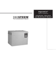
Typical piping and wiring
23XRV CHILLER
1
1
7
6
1
1
MAIN COMPRESSOR
MOTOR POWER
8
TO CHILLED LIQUID PUMP
TO CONDENSER LIQUID PUMP
TO COOLING TOWER FAN
2
9
TO
COOLING
TOWER
9
3
3
FROM
COOLING
TOWER
TO
LOAD
FROM
LOAD
DRAIN
5
4
1
2
3
4
5
6
7
8
9
—
—
—
—
—
—
—
—
—
LEGEND
Disconnect
Unit-Mounted VFD/Control Center
Pressure Gages
Chilled Liquid Pump
Condenser Liquid Pump
Chilled Liquid Pump Starter
Condenser Liquid Pump Starter
Cooling Tower Fan Starter
Vents
Piping
Control Wiring
Power Wiring
NOTES:
1. Wiring and piping shown are for general point-of-connection only and are not
intended to show details for a specific installation. Certified field wiring and
dimensional diagrams are available on request.
2. All wiring must comply with applicable codes.
3. Refer to Carrier System Design Manual for details regarding piping techniques.
4. Wiring not shown for optional devices such as:
• remote start/stop
• remote alarms
• optional safety device
• 4 to 20 mA resets
• optional remote sensors
• kW output
• head pressure reference
5. Flow switches are NOT required.
15
Control wiring schematic
23XRV COMPONENT ARRANGEMENT
CCM
CCN
ICVC
GND
16
—
—
—
—
LEGEND
Chiller Control Module
Carrier Comfort Network®
International Chiller Visual Controller
Ground
Application data
23XRV MACHINE FOOTPRINT
A
D
C
CL
VESSELS
CL
ACCESSORY
SOLEPLATE
COND.
B
TYP.
0’-3”
[76.2mm]
F
CL
COOLER
a23-1650
E
X
X*
G
0’-01/2”
[13mm]
TYP.
Y*
Y
*See detail on page 18.
23XRV
HEAT EXCHANGER
SIZE
30-32
35-37
40-42
45-47
50-52
55-57
DIMENSIONS (ft-in.)
DIMENSIONS (mm)
A
B
C
D
E
F
G
A
B
C
D
E
F
G
12-103/4
14- 71/4
12-103/4
14- 71/4
12-103/4
14- 71/4
5-41/4
5-41/4
6-0
6-0
6-51/2
6-51/2
0
0
0-11/2
0-11/2
0- 1/2
0- 1/2
0-35/8
0-35/8
0-35/8
0-35/8
0-35/8
0-35/8
1-13/4
1-13/4
1-13/4
1-13/4
1-13/4
1-13/4
0-9
0-9
0-9
0-9
0-9
0-9
0-1/2
0-1/2
0-1/2
0-1/2
0-1/2
0-1/2
3931
4451
3931
4451
3931
4451
1937
1937
1829
1829
1969
1969
0
0
38
38
13
13
92
92
92
92
92
92
349
349
349
349
349
349
229
229
229
229
229
229
13
13
13
13
13
13
17
Application data (cont)
23XRV ISOLATION WITH ACCESSORY SOLEPLATE PACKAGE
STANDARD ISOLATION
TYPICAL ISOLATION
ELASTOMERIC PAD
VIEW Y-Y
ISOLATION WITH ISOLATION PACKAGE ONLY
(STANDARD)
NOTE: Isolation package includes 4 elastomeric pads.
a23-1647
ACCESSORY SOLEPLATE DETAIL
VIEW X-X
NOTES:
1. Dimensions in ( ) are in millimeters.
2. Accessory soleplate package includes 4 soleplates, 16 jacking screws and leveling
pads. Requires isolation package.
3. Jacking screws to be removed after grout has set.
4. Thickness of grout will vary, depending on the amount necessary to level chiller. Use
only pre-mixed non-shrinking grout, Ceilcote 748 or Chemrex Embeco 636 Plus
Grout, 0′-11/2″ (38.1) to 0′-21/4″ (57) thick.
5. Service clearance under the chiller is enhanced if leveling pads are not extended
along the entire length of the heat exchangers.
18
23XRV NOZZLE ARRANGEMENTS
NOZZLE-IN-HEAD WATERBOXES
DISCHARGE END
SUCTION END
FRAME 3
12
3
9
6
5
11
2
8
4
10
1
7
DISCHARGE END
SUCTION END
FRAMES 4 AND 5
NOZZLE ARRANGEMENT CODES FOR ALL 23XRV NOZZLE-IN-HEAD WATERBOXES
PASS
1
2
3
In
8
5
7
4
7
4
COOLER WATERBOXES
Arrangement
Out
Code*
5
A
8
B
9
C
6
D
6
E
9
F
PASS
1
2
3
In
11
2
10
1
10
1
CONDENSER WATERBOXES
Arrangement
Out
Code*
2
P
11
Q
12
R
3
S
3
T
12
U
*Refer to certified drawings.
19
Application data (cont)
23XRV NOZZLE ARRANGEMENTS (cont)
MARINE WATERBOXES
DISCHARGE END
SUCTION END
FRAME 3
NOZZLE ARRANGEMENT CODES
PASS
In
8
1
2
3
COOLER WATERBOXES
Arrangement
Out
Code
5
A
5
8
B
7
9
C
4
6
D
7
6
E
4
9
F
PASS
CONDENSER WATERBOXES
Arrangement
Out
Code
—
—
In
—
1
2
3
—
—
—
10
12
R
1
3
S
—
—
—
—
—
—
DISCHARGE END
SUCTION END
FRAMES 4, AND 5
NOZZLE ARRANGEMENT CODES
PASS
1
2
3
20
In
9
COOLER WATERBOXES
Arrangement
Out
Code
6
A
6
9
B
7
9
C
4
6
D
7
6
E
4
9
F
PASS
1
2
3
In
—
CONDENSER WATERBOXES
Arrangement
Out
Code
—
—
—
—
—
10
12
R
1
3
S
—
—
—
—
—
—
23XRV WATERBOX NOZZLE SIZES (Nozzle-In-Head and Marine Waterboxes
FRAME
SIZE
PRESSURE
psig (kPa)
3
150/300
(1034/2068)
4
150/300
(1034/2068)
5
150/300
(1034/2068)
NOMINAL PIPE SIZE (in.)
Cooler
Condenser
10
10
8
8
6
6
10
10
8
8
6
6
10
10
8
10
6
8
PASS
1
2
3
1
2
3
1
2
3
ACTUAL PIPE ID (in.)
Cooler
Condenser
10.020
10.020
7.981
7.981
6.065
6.065
10.020
10.020
7.981
7.981
6.065
6.065
10.020
10.020
7.981
10.020
6.065
7.981
RELIEF VALVE LOCATIONS
LOCATION
MUFFLER
COOLER
CONDENSER
OPTIONAL
STORAGE TANK
FRAME
SIZE
3-5
3-5
3-5
RELIEF VALVE
OUTLET SIZE
11/4-in. NPT FEMALE CONNECTOR
11/4-in. NPT FEMALE CONNECTOR
11/4-in. NPT FEMALE CONNECTOR
N/A
QUANTITY
1
1 or 2*
2
1-in. NPT FEMALE CONNECTOR
2
* Coolers without optional isolation require 2 relief valves.
NOTE: All valves relieve at 185 psig (1275 kPa).
RELIEF VALVE ARRANGEMENTS
WITH OPTIONAL ISOLATION OF DISCHARGE AND COOLER
WITH OPTIONAL ISOLATION
WITHOUT OPTIONAL ISOLATION
21
Application data (cont)
Vent and drain connections
/P[[MFJOIFBEXBUFSCPYFTIBWFWFOUBOEESBJODPOOFD
UJPOTPODPWFST.BSJOFXBUFSCPYFTIBWFWFOUBOEESBJO
DPOOFDUJPOTPOXBUFSCPYTIFMMT
1SPWJEFIJHIQPJOUTPGUIFDIJMMFSQJQJOHTZTUFNXJUIWFOUT
BOEUIFMPXQPJOUTXJUIESBJOT*GTIVUPGGWBMWFTBSFQSPWJE
FEJOUIFNBJOMJRVJEQJQFTOFBSUIFVOJUBNJOJNBMBNPVOU
PGTZTUFNMJRVJEJTMPTUXIFOUIFIFBUFYDIBOHFSTBSF
ESBJOFE5IJTSFEVDFTUIFUJNFSFRVJSFEGPSESBJOBHFBOE
TBWFTPOUIFDPTUPGSFUSFBUJOHUIFTZTUFNMJRVJE
*UJTSFDPNNFOEFEUIBUQSFTTVSFHBHFTCFQSPWJEFEBU
QPJOUTPGFOUFSJOHBOEMFBWJOHMJRVJEUPNFBTVSFQSFTTVSF
ESPQUISPVHIUIFIFBUFYDIBO HFS(BHFTNBZCFJOTUBMMFE
BTTIPXOJO1SFTTVSF(BHF-PDBUJPOUBCMF1SFTTVSFHBHFT
JOTUBMMFEBUUIFWFOUBOEESBJODPOOFDUJPOTEPOPUJODMVEF
OP[[MFQSFTTVSFMPTTFT
6TFBSFMJBCMFEJGGFSFOUJBMQSFTTVSFHBHFUPNFBTVSFQSFT
TVSFEJGGFSFOUJBMXIFOEFUFSNJOJOHMJRVJEGMPX3FHVMBSHBH
FTPGUIFSFRVJSFEQSFTTVSFSBOHFEPOPUIBWFUIFBDDVSBDZ
UPQSPWJEFBDDVSBUFNFBTVS FNFOUPGGMPXDPOEJUJPOT
PRESSURE GAGE LOCATION
NUMBER
OF
PASSES
1 or 3
2
GAGE LOCATION
(Cooler or Condenser)
One gage in each waterbox
Two gages in waterbox with nozzles
QFSUIFDVSSFOUWFSTJPOPGUIF"4)3"&MBUFTUFEJUJPO
DPEFVTJOHUIFUBCVMBUFE$GBDUPSTGPSFBDIWFTTFMTIPXOJO
UIFUBCMFCFMPX
23XRV RELIEF VALVE DISCHARGE PIPE SIZING
RELIEF
VESSEL
VALVE
FIELD
HEAT
FRAME REQUIRED
RATED
CONNECTION
C FACTOR C FACTOR
EXCHANGER
SIZE
SIZE (FPT)
(lb air/Min)
(lb air/Min)
30 to 32
43.4
70.8
1 1 /4 ″
35 to 37
49.5
70.8
1 1 /4 ″
40 to 42
50.4
70.8
1 1 /4 ″
COOLER
45 to 47
57.4
70.8
1 1 /4 ″
50 to 52
53.7
70.8
1 1 /4 ″
55 to 57
61.1
70.8
1 1 /4 ″
30 to 32
41.4
70.8
1 1 /4 ″
35 to 37
47.1
70.8
1 1 /4 ″
40 to 42
47.1
70.8
1 1 /4 ″
CONDENSER
45 to 47
53.7
70.8
1 1 /4 ″
50 to 52
51.2
70.8
1 1 /4 ″
55 to 57
58.3
70.8
1 1 /4 ″
$BSSJFSGVSUIFSSFDPNNFOETUI BUBOPYZHFOTFOTPSCF
JOTUBMMFEUPQSPUFDUQFSTPOOFM4FOTPSTIPVMECFBCMFUP
TFOTFUIFEFQMFUJPOPSEJTQMBDFNFOUPGPYZHFOJOUIFNB
DIJOFSPPNCFMPXWP MVNFPYZHFOQFS"4)3"&
MBUFTUFEJUJPO
Design pressures
%FTJHOBOEUFTUQSFTTVSFTGPSIFBUFYDIBOHFSTBSFMJTUFE
CFMPX
Relief valve discharge pipe sizing
4FFQBHFGPSOVNCFSPGSFMJFGWBMWFT
3FMJFGWBMWFEJTDIBSHFQJQJOH TJ[FTIPVMECFDBMDVMBUFE
DESIGN AND TEST PRESSURES (23XRV)
PRESSURES
Leak Test at Design Pressure*
Hydrostatic
Proof Test*
*Nitrogen/Helium.
22
SHELL SIDE
(Refrigerant)
psig
kPa
185
1276
—
—
204
1407
STANDARD TUBE SIDE
(Liquid)
psig
kPa
150
1034
195
1344
—
—
OPTIONAL TUBE SIDE
(Liquid)
psig
kPa
300
2068
390
2689
—
—
Insulation
23XRV MINIMUM FIELD-INSTALLED INSULATION
REQUIREMENTS
COMPONENT
Cooler
Misc. Liquid Lines
Economizer
Compressor Motor
SIZE
30-32
35-37
40-42
45-47
50-52
55-57
All Sizes
All Sizes
All Sizes
INSULATION
ft2
m2
96
8.9
108
10.0
109
10.1
122
11.3
115
10.7
130
12.1
21
2.0
20
1.9
17
1.6
Factory insulation — Thermal insulation is factoryprovided to the following areas:
• Cooler (not including waterbox)
• Suction line
• Compressor and motor
• Oil cooling line and oil return system line (oil and refrigerant lines at or near evaporator pressure are insulated)
• VFD cooling line (oil and refrigerant lines at or near
evaporator pressure are insulated)
• Motor cooling line
• Vaporizer
• Liquid line and discharge line
• Float chamber
• Optional economizer (including vent line and economizer muffler)
Factory insulation is not available for the waterboxes.
Insulation applied at the factory is 1/2-in. (13 mm) thick
closed cell and 1/2-in. (13 mm) open cell PVC-Nitrile foam.
Some parts of the chiller are also treated with an outer
layer of 3/16-in. (5 mm) thick vinyl. The 1/2-in. (13 mm)
closed cell foam has a thermal conductivity K value of
0.28 (BTU in.)/(hr sqft °F) [0.0404 W/(m °C)] and
conforms with Underwriters Laboratories (UL) Standard
94, Classification 94 HF-1. Both the 1/2-in. foam and the
3/16-in. vinyl layer will pass flammability test method
MVSS 302.
Field insulation — As indicated in the Condensation vs
Relative Humidity table, the factory insulation provides
excellent protection against condensation under most operating conditions. If temperatures in the equipment area
exceed the maximum design conditions, extra insulation is
recommended.
If the machine is to be field insulated, obtain the approximate areas from the Minimum Field-Installed Insulation
Requirements table.
Insulation of waterbox is made only in the field and this
area is not included in Minimum Field-Installed Insulation
Requirements table. When insulating the covers, allow for
service access and removal of covers. To estimate waterbox cover areas, refer to certified drawings.
High humidity jobsite locations may require field supplied and installed insulation on the float chamber, suction
housing, and the lower half of the condenser.
CONDENSATION VS RELATIVE HUMIDITY*
AMOUNT OF
CONDENSATION
None
Slight
Extensive
ROOM DRY-BULB TEMPERATURE
80 F (27 C)
90 F (32 C)
100 F (38 C)
% Relative Humidity
80
76
70
87
84
77
94
91
84
*These approximate figures are based on 35 F (1.7 C) saturated suction
temperature. A 2° F (1.1° C) change in saturated suction temperature
changes the relative humidity values by 1% in the same direction.
23
Guide specifications
Variable Speed Screw Chiller
HVAC Guide Specifications
4J[F 3BOHF
300 to 550 Tons (1055 to 1934 kW)
Nominal
$BSSJFS.PEFM/VNCFS 23XRV
Part 1 — General
4:45&. %&4$3*P5*0/
".JDSPQSPDFTTPSDPOUSPMMFE MJRVJEDIJMMFSTIBMMVTFB
TFNJIFSNFUJDTDSFXDPNQSFTTPSVTJOHSFGSJHFSBOU
)'$BPOMZ$IJMMFSSFGSJHFSBOUTIBMMOPUIBWFB
QMBOOFEQIBTFPVUEBUF
#*GBNBOVGBDUVSFSQSPQPTFTBMJRVJEDIJMMFSVTJOH
)$'$SFGSJHFSBOUXIJDIIBTBQMBOOFEQIBTF
PVUEBUFUIFOUIFNBOVGBDU VSFSTIBMMJODMVEFJOUIF
DIJMMFSQSJDF
"WBQPSBDUJWBUFEBMBSNTZTUFNDPOTJTUJOHPGBMM
BMBSNTTFOTPSTTBGFUJFTBOEWFOUJMBUJPOFRVJQ
NFOUBTSFRVJSFECZ"/4*"4)3"&4UBOEBSE
4BGFUZ$PEFGPS.FDIBOJDBM3FGSJHFSBUJPO
MBUFTUFEJUJPO
XJUIUIFRVPUBUJPO4ZTUFNTIBMM
CFDBQBCMFPGSFTQPOEJOHUP)$'$MFWFMT
PGQQN"MMPXBCMF&YQPTVSF-JNJU"&-
"GSFFTUBOEJOHSFGSJHFSBOUTUPSBHFUBOLBOE
QVNQPVUVOJUTIBMMCF QSPWJEFE5IFTUPSBHF
WFTTFMTTIBMMCFEFTJHOFEQFS"4.&4FDUJPO7***
%JWJTJPODPEFXJUIQTJHL1B
EFTJHOQSFTTVSF%PVCMFSFMJFGWBMWFTQFS"/4*
"4)3"&MBUFTUFEJUJPOTIBMMCFQSPWJEFE
5IFUBOLTIBMMJODMVEFBMJRVJEMFWFMHBHFBOE
QSFTTVSFHBHF5IFQVNQPVUVOJUTIBMMVTFB
TFNJIFSNFUJDSFDJQSPDBUJOHDPNQSFTTPSXJUI
XBUFSDPPMFEDPOEFOTFS$POEFOTFSXBUFSQJQ
JOHQIBTFNPUPSQPXFSBOEWPMUDPOUSPM
QPXFSTIBMMCFJOTUBMMFEBUUIFKPCTJUFCZUIF
JOTUBMMJOHDPOUSBDUPS
;FSPFNJTTJPOQVSHFVOJUDBQBCMFPGPQFSBUJOH
FWFOXIFOUIFDIJMMFSJTOPUPQFSBUJOH
#BDLVQSFMJFGWBMWFUPSVQUVSFEJTL
'BDUPSZJOTUBMMFEDIJMMFSQSFTTVSJ[JOHTZTUFNUP
QSFWFOUMFBLBHFPGOPODPOEFOTBCMFTJOUPUIF
DIJMMFSEVSJOHTIVUEPXOQFSJPET
1MBOUSPPNWFOUJMBUJPO
3FNPWBMBOEEJTQPTBMPGSFGSJHFSBOUBUUIFFOE
PGUIFQIBTFPVUQFSJPE
$IJMMFSTVUJMJ[JOHBQVSHFVOJUTIBMMJODMVEFJOUIF
NBDIJOFQSJDFUIFDPTUTUPQFSGPSNUIFGPMMPX
JOHSFHVMBSNBJOUFOBODFQSPDFEVSFT
B8FFLMZ$IFDLSFGSJHFSBOUDIBSHF
C2VBSUFSMZ$IBSHFQVSHFVOJUEFIZESBUPSBU
MFBTURVBSUFSMZNPSF PGUFOJGOFDFTTBSZ
$MFBOGPVMHBTTUSBJOFS1FSGPSNDIFNJDBM
BOBMZTJTPGPJM
D"OOVBMMZ$MFBOBOEJOTQFDUBMMWBMWFT%SBJO
BOEGMVTIQVSHFTIFMM$MFBOPSJGJDFT
2
26"-*5:"4463"/$&
"$IJMMFSQFSGPSNBODFTIBMMCFSBUFEJOBDDPSEBODF
XJUI"3*4UBOEBSEMBUFTUFEJUJPO
#&RVJQNFOUBOEJOTUBMMBUJPOTIBMMCFJODPNQMJBODF
XJUI"/4*"4)3"&MBUFTUFEJUJPO
$$PPMFSBOEDPOEFOTFSTIPVMECFDPNQMJBOUXJUI
$IJOB$PEF(#(#
+#5
%$IJMMFSTIPVMECFEJTJHOFEBOEDPOTUSODUFEUPNFFU
$IJOBDPEF(#5SFRVJSFNFOU
&6OJUTIBMMCFNBOVGBDUVSFEJOBGBDJMJUZSFHJTUFSFEUP
*40.BOVGBDUVSJOH2VBMJUZ4UBOEBSE
'&BDIDPNQSFTTPSBTTFNCMZTIBMMVOEFSHPBNFDIBO
JDBMSVOJOUFTUUPWFSJGZWJCSBUJPOMFWFMTPJMQSFTTVSFT
BOEUFNQFSBUVSFTBSFXJUIJOBDDFQUBCMFMJNJUT&BDI
DPNQSFTTPSBTTFNCMZTIBMMCFQSPPGUFTUFEBUBNJOJ
NVNQTJHL1B
BOEMFBLUFTUFEBU
QTJHL1B
XJUIBUSBDFSHBTNJYUVSF
(&OUJSFDIJMMFSBTTFNCMZTIBMMCFQSPPGUFTUFEBU
QTJHL1B
BOEMFBLUFTUFEBUQTJH
L1B
XJUIBUSBDFSHBTNJYUVSFPOUIFSFGSJHFS
BOUTJEF5IFMFBLUFTUTIBMMOPUBMMPXBOZMFBLT
HSFBUFSUIBOP[QFSZFBSPGSFGSJHFSBOU5IF
XBUFSTJEFPGFBDIIFBUFYDIBOHFSTIBMMCFIZESP
TUBUJDBMMZUFTUFEBUUJNFTSBUFEXPSLJOHQSFTTVSF
)1SJPSUPTIJQNFOUUIFDIJMMFSBVUPNBUFEDPOUSPMT
UFTUTIBMMCFFYFDVUFEUPDIFDLGPSQSPQFSXJSJOHBOE
FOTVSFDPSSFDUDPOUSPMTPQFSBUJPO
* $IJMMFSTTIBMMIBWFGBDUPSZNPVOUFEGBDUPSZXJSFE
BOEGBDUPSZUFTUFEVOJUNPVOUFEWBSJBCMFGSFRVFODZ
ESJWF7'%
1SPQFS7'%PQFSBUJPOTIBMMCFDPO
GJSNFEQSJPSUPTIJQNFOU
%&-*7&3:4503"(&"/%)"/%-*/(
" 6OJUTIBMMCFTUPSFEBOEIBOEMFEJOBDDPSEBODFXJUI
NBOVGBDUVSFSTJOTUSVDUJPOT
# 6OJUTIBMMCFTIJQQFEXJUIBMMSFGSJHFSBOUQJQJOHBOE
DPOUSPMXJSJOHGBDUPSZJOTUBMMFE
$6OJUTIBMMCFTIJQQFEDIBSHFEXJUIPJMBOEGVMM
DIBSHFPGSFGSJHFSBOU)'$BPSBOJUSPHFOIPME
JOHDIBSHFBTTQFDJGJFEPOUIFFRVJQNFOUTDIFEVMF
D. Unit shall be shipped with firmly attached labels that
indicate name of manufacturer, chiller model number, chiller serial number, and refrigerant used.
E. If the unit is to be exported, the manufacturer shall
provide sufficient protection against sea water corrosion, making the unit suitable for shipment in a
standard open top ocean shipping container.
F. Chiller and starter shall be stored indoors, protected
from construction dirt and moisture. Chiller shall be
inspected under shipping tarps, bags, or crates to be
sure water has not collected during transit. Protective shipping covers shall be kept in place until
machine is ready for installation. The inside of the
protective cover shall meet the following criteria:
1. Temperature is between 40 F (4.4 C) and
120 F (48.9 C)
2. Relative humidity is between 10% and 80%
non-condensing.
1.04 WARRANTY
Warranty shall include parts and labor for one year
after start-up or 18 months from shipment, whichever occurs first. A refrigerant warranty shall be
provided for a period of 5 years.
Part 2 — Products
2.01 EQUIPMENT
A. General:
Factory-assembled, single piece, liquid chiller shall
consist of compressor, motor, VFD, lubrication system, cooler, condenser, initial oil and refrigerant
operating charges, microprocessor control system,
and documentation required prior to start-up.
B. Compressor:
1. One variable speed, tri-rotor screw compressor
of the high performance type.
2. Compressor and motor shall be hermetically
sealed into a common assembly and arranged
for easy field servicing.
3. The compressor motor shall be accessible for
servicing without removing the compressor
base from the chiller. Connections to the compressor casing shall use O-rings and gaskets to
reduce the occurrence of refrigerant leakage.
Connections to the compressor shall be flanged
or bolted for easy disassembly.
4. Compressor bearings must have individual
design life of 500,000 hours or greater.
5. Compressor shall provide capacity modulation
from 100% to 15% capacity without the use of
hot gas bypass or mechanical unloaders.
6. Compressor shall be provided with a factoryinstalled positive pressure lubrication system to
deliver oil under pressure to bearings and rotors
at all operating conditions. Lubrication system
shall include:
a. Oil pump with factory-installed motor contactor with overload protection.
b. Oil pressure sensor with differential readout
at main control center.
c. Oil pressure regulator.
d. Oil filter with isolation valves to allow filter
change without removal of refrigerant
charge.
e. Oil sump heater [115 v, 50 or 60 Hz] controlled from unit microprocessor.
f. Oil reservoir temperature sensor with main
control center digital readout.
g. All wiring to oil pump, oil heater, and controls shall be pre-wired in the factory and
power shall be applied to check proper
operation prior to shipment.
7. Compressor shall be fully field serviceable.
Compressors that must be removed and
returned to the factory for service shall be
unacceptable.
8. Acoustical attenuation shall be provided as
required, to achieve a maximum (full load
or part load) sound level, measured per ARI
Standard 575 (latest edition).
C. Motor:
1. Compressor motor shall be of the semihermetic, liquid refrigerant cooled, squirrel
cage, induction type suitable for voltage shown
on the equipment schedule.
2. If an open (air cooled) motor is provided, a
compressor shaft seal leakage containment
system shall be provided:
a. An oil reservoir shall collect oil and refrigerant that leaks past the seal.
b. A float device shall be provided to open
when the reservoir is full, directing the
refrigerant/oil mixture back into the compressor housing.
c. A refrigerant sensor shall be located next to
the open drive seal to detect leaks.
3. Motors shall be suitable for operation in a
refrigerant atmosphere and shall be cooled by
atomized refrigerant in contact with the motor
windings.
4. Motor stator shall be arranged for service or
removal with only minor compressor disassembly and without removing main refrigerant
piping connections.
5. Full load operation of the motor shall not
exceed nameplate rating.
6. One motor winding temperature sensor (and on
spare) shall be provided.
7. Should the mechanical contractor choose to
provide a chiller with an air-cooled motor
instead of the specified semi-hermetic motor,
the contractor shall install additional cooling
25
Guide specifications (cont)
equipment to dissipate the motor heat as per
the following formula:
Btuh = (FLkW motor) (0.05) (3413)
Btuh = (FLkW motor) (171)
and, alternately
Tons = Btuh/12,000
The additional piping, valves, air-handling
equipment, insulation, wiring, switchgear
changes, ductwork, and coordination with other
trades shall be the responsibility of the mechanical contractor. Shop drawings reflecting any
changes to the design shall be included in the
submittal, and incorporated into the final asbuilt drawings for the project.
8. Also, if an open motor is provided, a mechanical room thermostat shall be provided and set
at 104 F (40 C). If this temperature is
exceeded, the chillers shall shut down and an
alarm signal shall be generated to the central
Energy Management System (EMS) display
module, prompting the service personnel to
diagnose and repair the cause of the overtemperature condition. The mechanical contractor
shall be responsible for all changes to the
design, including coordination with temperature
control, electrical and other trades. In addition,
the electrical power consumption of any auxiliary ventilation and/or mechanical cooling
required to maintain the mechanical room conditions stated above shall be considered in the
determination of conformance to the scheduled
chiller energy efficiency requirement.
D. Unit-Mounted Variable Frequency Drive (VFD) with
Built-In Harmonic LiquiFlo™ II Filter:
The compressor shall be factory-mounted, factorywired and factory-tested prior to shipment by the
chiller manufacturer. All interconnecting wiring and
piping between the VFD and the chiller shall be
factory-installed. Customer electrical connection for
compressor motor power shall be limited to main
power leads to the VFD, and wiring liquid pumps
and tower fans to the chiller control circuit. The
VFD shall incorporate the following features:
1. Design:
a. The VFD shall be refrigerant cooled,
microprocessor based, pulse width modulated design. Water cooled designs are not
acceptable.
b. Input and output power devices shall be
Insulated Gate Bipolar Transistors (IGBTs).
c. Active rectifier shall convert incoming fixed
voltage/frequency to fixed DC voltage. Input
current and voltage shall be regulated.
d. Transistorized inverter and control regulator
shall convert fixed DC voltage to a sinusoidal
PWM waveform.
e. Low voltage control sections and main
power sections shall be physically isolated.
26
2.
3.
4.
5.
6.
f. Integrated controls shall coordinate motor
speed to optimize chiller performance over a
wide variety of operating conditions.
Enclosure:
a. Pre-painted unit mounted, NEMA 1 cabinet
shall include hinged, lockable doors and
removable lifting lugs.
b. The VFD shall have a short circuit interrupt
and withstand rating of at least 65,000 amps.
c. Provisions to padlock main disconnect handle in the “Off” positions shall be provided.
Mechanical interlock to prevent opening
cabinet door with disconnect in the “On”
position or moving disconnect to the “On”
position while the door is open shall be
provided.
d. Provisions shall be made for top entry of
incoming line power cables.
Heat Sink:
a. The heat sink shall be refrigerant cooled.
Heat sink and mating flanges shall be suitable for ASME design working pressure of
185 psig (1276 kPa).
b. Refrigerant cooling shall be metered by
microprocessor-controlled solenoid valve to
maintain heat sink temperature within
acceptable limits for ambient temperature.
VFD Rating:
a. Drive shall be suitable for operation at nameplate voltage ±10%.
b. Drive shall be suitable for continuous operation at 100% of nameplate amps and 150%
of nameplate amps for 5 seconds.
c. Drive shall comply with applicable ANSI,
NEMA, UL and NEC standards.
d. Drive shall be suitable for operation in ambient
temperatures between 40 and 122 F (4 and
50 C), 95% humidity (non-condensing) for
altitudes up to 6000 ft (1829 m) above sea
level. Specific drive performance at jobsite
ambient temperature and elevation shall be
provided by the manufacturer in the bid.
User Interface:
A single display shall provide interface for programming and display of VFD and chiller
parameters. Viewable parameters include:
a. Operating, configuration and fault messages
b. Frequency in hertz
c. Load and line side voltage and current (at the
VFD)
d. kW
e. IGBT temperature
VFD Performance:
a. The VFD Voltage Total Harmonic Distortion
(THD) and Harmonic Current Total Demand
Distortion (TDD) shall not exceed IEEE-519
Guide specifications (cont)
9. The condenser shell shall include a FLASC
(Flash Subcooler) which cools the condensed
liquid refrigerant to a reduced temperature,
thereby increasing the refrigeration cycle
efficiency.
F. Refrigerant Flow Control:
To improve part-load efficiency, liquid refrigerant
shall be metered from the condenser to the cooler
using a float-type metering valve to maintain the
proper liquid level of refrigerant in the heat
exchangers under both full and part load operating
conditions. By maintaining a liquid seal at the float
valve, bypassed hot gas from the condenser to the
cooler is eliminated.
G. Controls, Safeties, and Diagnostics:
1. Controls:
a. The chiller shall be provided with a factoryinstalled and factory-wired microprocessor
control center. The control center shall include
a 16-line by 40-character liquid crystal display,
4 function keys, stop button, and alarm light.
Other languages are available using the international language translator software.
b. All chiller and motor control monitoring shall
be displayed at the chiller control panel.
c. The controls shall make use of non-volatile
memory.
d. The chiller control system shall have the ability
to interface and communicate directly to the
building control system.
e. The default standard display screen shall simultaneously indicate the following minimum
information:
1) Date and time of day
2) 24-character primary system status
message
3) 24-character secondary status message
4) Chiller operating hours
5) Entering chilled water temperature
6) Leaving chilled water temperature
7) Evaporator refrigerant temperature
8) Entering condenser water temperature
9) Leaving condenser water temperature
10) Condenser refrigerant temperature
11) Oil supply pressure
12) Oil sump temperature
13) Percent motor rated load amps (RLA)
f. In addition to the default screen, status
screens shall be accessible to view the status
of every point monitored by the control
center including:
1) Evaporator pressure
2) Condenser pressure
3) Compressor speed
4) Bearing oil supply temperature
5) Compressor discharge temperature
6) Motor winding temperature
7) Number of compressor starts
28
g.
h.
i.
j.
k.
8) Control point settings
9) Discrete output status of various devices
10) Variable frequency drive status
11) Optional spare input channels
12) Line current and voltage for each phase
13) Frequency, kW, kWhr, demand kW
Schedule Function:
The chiller controls shall be configurable for
manual or automatic start-up and shutdown.
In automatic operation mode, the controls
shall be capable of automatically starting and
stopping the chiller according to a stored
user programmable occupancy schedule.
The controls shall include built-in provisions
for accepting:
1) A minimum of two 365-day occupancy
schedules.
2) Minimum of 8 separate occupied/unoccupied periods per day
3) Daylight savings start/end
4) 18 user-defined holidays
5) Means of configuring an occupancy
timed override
6) Chiller start-up and shutdown via remote
contact closure
Service Function:
The controls shall provide a password
protected service function which allows
authorized individuals to view an alarm
history file which shall contain the last
25 alarm/alert messages with time and date
stamp. These messages shall be displayed in
text form, not codes.
Network Window Function:
Each chiller control panel shall be capable of
viewing multiple point values and statuses
from other like controls connected on a
common network, including controller maintenance data. The operator shall be able to
alter the remote controller’s set points or
time schedule and to force point values or
statuses for those points that are operator
forcible. The control panel shall also have
access to the alarm history file of all like controllers connected on the network.
Pump Control:
Upon request to start the compressor, the
control system shall start the chilled and
condenser water pumps and shall verify that
flows have been established.
Ramp Loading:
A user-configurable ramp loading rate, effective during the chilled water temperature
pulldown period, shall prevent a rapid
increase in compressor power consumption.
The controls shall allow configuration of the
ramp loading rate in either degrees per
minute of chilled water temperature pulldown or percent motor amps per minute.
During the ramp loading period, a message
shall be displayed informing the operator
that the chiller is operating in ramp loading
mode.
l. Chilled Water Reset:
The control center shall allow reset of the
chilled water temperature set point based on
any one of the following criteria:
1) Chilled water reset based on an external
4 to 20 mA signal.
2) Chilled water reset based on a remote
temperature sensor (such as outdoor
air).
3) Chilled water reset based on water temperature rise across the evaporator.
m. Demand Limit:
The control center shall limit amp draw of
the compressor to the rated load amps or to
a lower value based on one of the following
criteria:
1) Demand limit based on a user input
ranging from 40% to 100% of compressor rated load amps
2) Demand limit based on external 4 to
20 mA signal.
n. Controlled Compressor Shutdown:
The controls shall be capable of being
configured to soft stop the compressor. The
display shall indicate “shutdown in progress.”
2. Safeties:
a. Unit shall automatically shut down when any
of the following conditions occur (each of
these protective limits shall require manual
reset and cause an alarm message to be displayed on the control panel screen, informing the operator of the shutdown cause):
1) Motor overcurrent
2) Over voltage*
3) Under voltage*
4) Single cycle dropout*
5) Low oil sump temperature
6) Low evaporator refrigerant temperature
7) High condenser pressure
8) High motor temperature
9) High compressor discharge temperature
10) Low oil pressure
11) Prolonged stall
12) Loss of cooler water flow
13) Loss of condenser water flow
14) Variable frequency drive fault
15) High variable frequency drive temperature
* Shall not require manual reset or cause an
alarm if auto-restart after power failure is
enabled.
b. The control system shall detect conditions
that approach protective limits and take selfcorrective action prior to an alarm occurring. The system shall automatically reduce
chiller capacity when any of the following
parameters are outside their normal operating range:
1) High condenser pressure
2) High motor temperature
3) Low evaporator refrigerant temperature
4) High motor amps
5) High VFD rectifier temperature
6) High VFD inverter temperature
c. During the capacity override period, a prealarm (alert) message shall be displayed
informing the operator which condition is
causing the capacity override. Once the condition is again within acceptable limits, the
override condition shall be terminated and
the chiller shall revert to normal chilled
water control. If during either condition the
protective limit is reached, the chiller shall
shut down and a message shall be displayed
informing the operator which condition
caused the shutdown and alarm.
d. Internal built in safeties shall protect the
chiller from loss of water flow. Differential
pressure switches shall not be allowed to be
the only form of freeze protection.
3. Diagnostics and Service:
a. A self diagnostic controls test shall be an
integral part of the control system to allow
quick identification of malfunctioning
components.
b. Once the controls test has been initiated, all
pressure and temperature sensors shall be
checked to ensure they are within normal
operating range. A pump test shall automatically energize the chilled water pump, condenser water pump, and oil pump. The
control system shall confirm that water flow
and oil pressure have been established and
require operator confirmation before proceeding to the next test.
c. In addition to the automated controls test,
the controls shall provide a manual test
which permits selection and testing of individual control components and inputs. A
thermistor test and transducer test shall display on the ICVC screen the actual reading
of each transducer and each thermistor
installed on the chiller. All out-of-range sensors shall be identified. Pressure transducers
shall be serviceable without the need for
refrigerant charge removal or isolation.
4. Multiple Chiller Control:
The chiller controls shall be supplied as standard with a two-chiller lead/lag and a third
chiller standby system. The control system shall
automatically start and stop a lag or second
chiller on a two-chiller system. If one of the two
chillers on line goes into a fault mode, the third
standby chiller shall be automatically started.
29
Guide specifications (cont)
H.
I.
J.
K.
L.
30
The two-chiller lead/lag system shall allow manual rotation of the lead chiller and a staggered
restart of the chillers after a power failure. The
lead/lag system shall include load balancing if
configured to do so.
Electrical Requirements:
1. Electrical contractor shall supply and install
main electrical power line, disconnect switches,
circuit breakers, and electrical protection
devices per local code requirements and as indicated necessary by the chiller manufacturer.
2. Electrical contractor shall wire the chilled water
pump and flow, condenser water pump and
flow, and tower fan control circuit to the chiller
control circuit.
3. Electrical contractor shall supply and install
electrical wiring and devices required to interface the chiller controls with the building control
system if applicable.
4. Electrical power shall be supplied to the unit at
the voltage, phase, and frequency listed in the
equipment schedule.
Piping Requirements — Instrumentation and Safeties:
1. Mechanical contractor shall supply and install
pressure gages in readily accessible locations in
piping adjacent to the chiller such that they can
be easily read from a standing position on the
floor. Scale range shall be such that design values shall be indicated at approximately midscale.
2. Gages shall be installed in the entering and leaving water lines of the cooler and condenser.
Vibration Isolation:
Chiller manufacturer shall furnish neoprene isolator
pads for mounting equipment on a level concrete
surface.
Start-Up:
1. The chiller manufacturer shall provide a factorytrained representative, employed by the chiller
manufacturer, to perform the start-up procedures as outlined in the Start-Up, Operation
and Maintenance manual provided by the
chiller manufacturer.
2. Manufacturer shall supply the following
literature:
a. Start-up, operation and maintenance
instructions.
b. Installation instructions.
c. Field wiring diagrams.
d. One complete set of certified drawings.
Special Features:
1. Soleplate Package:
Unit manufacturer shall furnish a soleplate
package consisting of soleplates, jacking
screws, leveling pads, and neoprene pads.
2. Spring Isolators:
Spring isolators shall be field furnished and
selected for the desired degree of isolation.
3. Spare Sensors with Leads:
Unit manufacturer shall furnish additional temperature sensors and leads.
4. Sound Insulation Kit:
Unit manufacturer shall furnish a sound insulation kit that covers the compressor housing,
motor housing, compressor discharge pipe,
suction line, evaporator, and economizer (if
equipped).
5. Stand-Alone Pumpout Unit:
A free-standing pumpout unit shall be provided.
The pumpout unit shall use a semi-hermetic
reciprocating compressor with liquid-cooled
condenser. Condenser liquid piping and
3-phase motor power shall be installed at the
jobsite by the installing contractor.
6. Separate Storage Tank and Pumpout Unit:
A free-standing refrigerant storage tank and
pumpout unit shall be provided. The storage
vessels shall be designed per ASME Section VIII
Division 1 code with 150 psig (1034 kPa)
design pressure. Double relief valves per ANSI/
ASHRAE 15, latest edition, shall be provided.
The tank shall include a liquid level gage and
pressure gage. The pumpout shall use a
hermetic reciprocating compressor with watercooled condenser. Condenser water piping and
3-phase motor power shall be installed at the
jobsite by the installing contractor.
7. Building Control System Interface (LON):
The chiller control system shall have the ability
to interface and communicate directly to the
building control using a LON based system. The
LonWorks™ Carrier Translator shall output data
in standard LON profiles.
8. Building Control System Interface (BACnet™):
The chiller control system shall have the ability
to interface and communicate directly to the
building control using a BACnet based system.
9. Refrigerant Charge:
The chiller shall ship from the factory fully
charged with R-134a refrigerant and oil.
10. Thermal Insulation:
Unit manufacturer shall insulate the cooler
shell, economizer, suction elbow, motor shell
and motor cooling lines. Insulation shall be 1 in.
(25.4 mm) thick with a thermal conductivity not
exceeding
0.28
(Btu · in.)
hr.
Ft2
F
( 0.0404
W
mC
)
and shall conform to UL standard 94, classification 94 HF-1.
11. Automatic Hot Gas Bypass:
Hot gas bypass valve and piping shall be
factory-furnished to permit chiller operation for
extended periods of time.
12. Cooler and Condenser Tubes:
Contact a local Carrier Representative for other
tube offerings.
13. Cooler and Condenser Passes:
Unit manufacturer shall provide the cooler and/
or condenser with 1, 2 or 3 pass configuration
on the water side.
14. Nozzle-In-Head, 300 psig (2068 kPa):
Unit manufacturer shall furnish nozzle-in-head
style waterboxes on the cooler and/or condenser rated at 300 psig (2068 kPa).
15. Marine Waterboxes:
Unit manufacturer shall furnish marine style
waterboxes on cooler and/or condenser rated
at 150 psig (1034 kPA).
16. Marine Waterboxes:
Unit manufacturer shall furnish marine style
waterboxes on cooler and/or condenser rated
at 300 psig (2068 kPA).
17. Flanged Water Nozzles:
Unit manufacturer shall furnish standard
flanged piping connections on the cooler and/
or condenser.
18. Hinges:
Unit manufacturer shall furnish hinges on
waterboxes to facilitate tube cleaning.
19. Optional Compressor Discharge Isolation Valve
and Liquid Line Ball Valve:
These items shall be factory-installed to allow
isolation of the refrigerant charge in the condenser for servicing the compressor.
20. Pumpout Unit:
A refrigerant pumpout system shall be installed
on the chiller. The pumpout system shall
include a hermetic compressor and drive, internal piping, internal wiring, and motor. Fieldsupplied main power wiring and water piping
shall be required.
31
The Manufacturer reserves the right to change any produt specifications without prior notices
Version:
Supersede:
EFfective Date:
CAT_23XRV_E-1205_01
23xrv-2pd
May, 2012