1
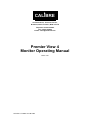
CALIBRE Cornwall House, Cornwall Terrace, Bradford, West Yorkshire, BD8 7JS UK Telephone: 01274-394125 Fax: 01274-730960 E-mail: [email protected] Premier View 4 Monitor Operating Manual Issue 4.03 27/03/03 Calibre UK Ltd 2003 CALIBRE Welcome to the Calibre LCD monitor Operating Manual If you have any queries relating to this or any other product supplied by Calibre please visit our web site www.calibreuk.com. For support or further information please contact a sales representative at. Issue 4.03 Cornwall House, Cornwall Terrace Bradford, BD8 7JS. UK. Tel: (+44) (0)1274 394125. Fax: (+44) (0)1274 730 960 E-mail: [email protected] Web site www.calibreuk.com All World-wide Rights Reserved 27/03/03 All trade marks acknowledged Calibre operates a policy of continued product improvement, therefore specifications are subject to change without notice as products are updated or revised. E&OE. Issue 4.03 27/03/03 Calibre UK Ltd 2003 Page i CALIBRE CONTENTS Contents..............................................................................................................................................ii PRODUCT DESCRIPTION ................................................................................................................1 1.1. Introduction ...............................................................................................................1 1.2. Product Overview .....................................................................................................1 OPERATION.......................................................................................................................................3 2.1. Normal Operation .....................................................................................................3 2.2. User Interface Buttons ..............................................................................................3 2.3. User Controls............................................................................................................4 2.4. OSD Menu ................................................................................................................4 ENVIRONMENTAL AND SAFETY .....................................................................................................8 3.1. Operating ..................................................................................................................8 3.2. Storage .....................................................................................................................8 3.3. Safety Issues ............................................................................................................8 PRODUCT SPECIFICATION .............................................................................................................9 4.1. Introduction ...............................................................................................................9 4.2. Video Inputs ..............................................................................................................9 4.3. Computer (RGB and DVI) Inputs ..............................................................................9 4.4. SDI Input...................................................................................................................9 4.5. DVI Input...................................................................................................................9 4.6. Component Video Input ............................................................................................10 ABBREVIATIONS ...............................................................................................................................11 Issue 4.03 27/03/03 Calibre UK Ltd 2003 Page ii CALIBRE PRODUCT DESCRIPTION 1.1. Introduction This manual is intended to give an operator information to facilitate connection, setting up, and usage of the monitor which is fitted with a PremierView 4 flat-panel driver card. Its technical content is limited to that which is relevant to these functions; full technical information is given in the Technical Manual. The figure below details all the possible input connections please check your monitor or product description to determine which inputs are fitted. 1.2. Product Overview The monitor is designed to accept the following input signals: • Composite video via BNC socket or 3-pin header • S-Video via 4-way mini_DIN socket • RGB and YUV component video via 10-pin header on open-chassis units or 4 off BNC sockets on cased units. • SDI (Serial Digital Interface) via 3-pin header on open-chassis units or a BNC sockets on cased units. • RGB analogue (computer interface) via 15-way HDD socket or 10-pin header • DVI (Digital Visual Interface) via DVI socket (Molex 88741 series or similar) These signals can be all displayed on the panel and ALL signals are displayed FULL SCREEN. "Near-optical quality" scaling means that the output signal is scaled with minimal loss of quality or image resolution irrespective of the resolution of the incoming signal. Issue 4.03 27/03/03 Calibre UK Ltd 2003 Page 1 CALIBRE Factory defaults have been carefully chosen such that most users will not need to make any adjustments. A simple user interface (supplied) with On Screen Display allows the user to adjust a wide variety of parameters if necessary. Once the parameters are set they can be stored in non-volatile EEPROM, which ensures the set-up is retained when power to the unit is switched off. Issue 4.03 27/03/03 Calibre UK Ltd 2003 Page 2 CALIBRE OPERATION 2.1. Normal Operation Normal operation of the interface consists of little more than connecting up the power supply, video and computer signals and switching on. Signals are scanned in accordance with the currently selected priority list and the highest priority valid signal is displayed. If the priority or any other picture parameter needs adjustment then the following section describes the user interface. VIDEO Brightness GRAPHICS Controls backlight intensity Contrast Geometry Controls video gain Image edge adjust (size and position), Moire correction, aspect ratio. For SXGA, choice of Full scan, overscan or letter-box aspect ratios. Input Select Colour Image edge adjust (size and position), Moire correction, clock (tune), phase (sharpness) RGB, DVI,CVBS, Y/C, Component Video Colour, contrast, black level, hue (NTSC only), gamma correction System Contrast, black level, R+G+B gains, R+G+B levels, gamma correction ESC, Save, Reset, OSD timeout, OSD X/Y position, Auto Centering Auto Setup Not applicable Miscellaneous Yes/No (analogue graphics only) Image flip horizontal Some models allow the user to flip the image vertically NOTE for Graphics inputs SVGA is the maximum resolution which can be flipped vertically Function-dependent Menu Options. 2.2. User Interface Buttons The physical user control panel consists of five push buttons. One of these is dedicated to invoking the OSD Menu while the other four are dual purpose, as listed below: • Menu: invokes OSD or next function level (equivalent to “enter” key on a PC) • Con+: Direct contrast increase, also used to increment selected parameter • Con-: Direct contrast decrease, also used to decrement selected parameter • BR+: Direct backlight increase, also used to increment selected parameter • BR-: Direct backlight decrease, also used to decrement selected parameter Issue 4.03 27/03/03 Calibre UK Ltd 2003 Page 3 CALIBRE 2.3. User Controls. 2.3.1. Direct Brightness Adjustment Pressing the Br+ or BR- button controls the intensity of the backlight. After adjustment, the new Brightness value is displayed on the screen until the OSD timeout period expires (see para. 2.4.5). The new setting is then stored and the display returns to normal. 2.3.2. Direct Contrast Adjustment Pressing the Con+ or Con- button controls the contrast (video gain) of the picture. After adjustment, the new contrast value is displayed on the screen until the OSD timeout period expires. The new setting is then stored and the display returns to normal. 2.3.3. Menu Select Pressing this button displays picture identification information together with a menu of icons. To access lower-level functions, press Con+, Con-, Br+ or Br- to toggle through the menus available for the currently displayed signal type, then press MENU again to select that function. The MENU button has a similar function to the ENTER key on a computer keyboard. Exit from a menu is by selecting BACK which returns to the previous level. When leaving the main menu you will be prompted to save any changes, if you do not wish to save any changes select NO. Note that Con+ and Br+ have identical functions in this mode, as have Con- and Br-. 2.4. OSD Menu At the top of the menu is a line which identifies the type of signal currently displayed. For computer signals the same section displays the signal resolution, together with horizontal and vertical frequencies. If its setup has been saved, the user number of that signal is also displayed. These figures are for guidance only. 2.4.1. Brightness and Contrast These perform the same functions as the direct button operations in para. 2.3.1 and 2.3.2 above. 2.4.2. The Geometry Menu Geometry adjustments can be made for all types of input individually, so that if the input type changes, the geometry adjustment will change with it. Saved settings include one each for PAL, NTSC, SECAM, SDI and component video. Additionally, a total of 25 settings may be stored for analogue graphics (RGB and DVI). If this graphics table is full, further stored settings will over-write the earliest so that the settings complement contains the latest 25. 1) Edge Adjustment – Picture Size and Position Controls. The four “Edge” controls shift each edge within available limits. Note that the maximum available shift depends on the incoming video standard and the display panel type, and may be restricted vertically. This provides very flexible and easy to use image size and position control. 2) Moire correction The user can choose from one of four correction tables. 3) Clock (Analogue Graphics only). This sets the total number of input pixels per line to correspond with the input source, and will normally require adjustment only for unusual signals. 4) Phase (Analogue Graphics only) This adjusts the internal clock to sample each pixel as near as possible to the centre. Phase will normally require adjustment for unusual types of signal. Issue 4.03 27/03/03 Calibre UK Ltd 2003 Page 4 CALIBRE 5) 2.4.3. Aspect Ratio (Video signals only for SXGA panels) This allows a user to select the displayed aspect ratio where the signal input is at variance with the display panel’s natural aspect ratio. The format may be adjusted to either “Letter Box” (4:3 LB) or “Overscan” (4:3 OS). “Letter Box” effectively adjusts the height of the displayed image and “Overscan” effectively adjusts the width to achieve the desired 4:3 aspect ratio. Input Select This allows the user to configure the preferred input selections. If a facility is not fitted, it will be displayed but not selectable. By pressing the Br+/Con+ and Br-/Con- keys, the following choices can be made: 1) Signal type priority: Video-graphics or Graphics-video 2) Video priority search order – CVBS – Y/C – SDI – Component Y/C – CVBS – SDI – Component SDI – Component – CVBS – Y/C Component – SDI – CVBS – Y/C 3) Graphics search – RGB-DVI or DVI-RGB 4) Component video type – RGB or YUV. Incorrect colours may be due to wrong selection here. NOTE you can only select those inputs which your monitor is configured for. 2.4.4. The Colour Menu 1) Video Inputs - The contrast (video gain) and brightness (black level) parameters, also colour saturation for PAL, NTSC and SECAM inputs can be accessed from this menu. For NTSC signals, there is an additional HUE option. 2) Computer Inputs – Individual Colour Adjustments - Red, green and blue levels can be thought of as individual brightness controls for each of red, green and blue. They should be adjusted for the desired colour balance and to minimise noise on low intensity colours and greys. Colour tints can be added as required. Gains can be thought of as individual contrast controls for each of red, green and blue. They should be adjusted for the desired colour balance and lack of noise on high intensity colours and whites. For example, a block of white can be changed to a blue-tinge (clean) white or to a red-tinge (warm) white. Issue 4.03 27/03/03 Calibre UK Ltd 2003 Page 5 CALIBRE 2.4.5. The System Menu This selection contains functions which are more applicable to system operation than to picture adjustment: 1) Esc: The Esc option returns to the last saved setup. It is useful if an adjustment has been made in error. After an Esc the menu is removed. 2) Save: The Save option saves all the user adjustments for the displayed signal type. The new adjustments are stored in non-volatile memory and so are still valid from a power down - power up cycle. After a Save the menu is removed. 3) Reset: The are two types of Reset option: Selecting Reset from the menu restores the user adjustable parameters for the signal currently being display back to the factory defaults. Simultaneously pressing four buttons Br+, Br–, Con+, Con– restores to factory default state all the user adjustments for the signal currently being displayed. This is useful if a picture set-up has become hopelessly lost or confused. The Reset option can also be accessed even if the OSD has been lost. After a Reset the menu is removed. 4) OSD Timeout: This selection enables the user to control the time after which the OSD display is cancelled. It can be adjusted in 15-sec increments from 1 (=15 sec) to 4 (=1 min) approximately. 5) OSD X and OSD Y: These functions control the position of the OSD display on the screen. Its default setting is such as to place the OSD in the centre of the screen, but the user can adjust its position with these functions. 6) Auto Centering: This is simply a Yes/No selection. If an input signal changes, it is first measured and compared with stored selections. If its parameters are already stored, they are installed. If they are not stored, the “Auto Centering” selection is checked and if set to “No” the best fit is displayed. The user can then centre the picture using OSD auto setup. If Auto Centering is set to “Yes”, centering is performed automatically, which may take more than 15 seconds. This could cause a problem if using Windows, wherein a resolution change is displayed only for 15 seconds and reverts to its previous selection if no acknowledgement is entered. For this reason, the default state is “No”. NOTE this control only configures Analogue Graphics inputs. 7) Computer / AV Mode: This option is only available on units fitted with the professional decoder and is valid when the input is RGB(S) connected via the component input port or an interlace graphics signal is connected via the analog computer input port. Computer Mode should be selected when the input comes from a computer generated source, this option provides reduced flicker for predominantly static data. AV Mode should be selected when the input comes from any source which contains moving images as it provides a smoother output. 2.4.6. The Miscellaneous Menu This selection offers several options the availability of these functions is dependant on the particular build configuration and the signal input. 1) Image flip Horizontal: This is available on the majority of options and allows the user to flip the output image horizontally. 2) Image Flip Vertical: This can only be used if the Frame Store option is fitted and the input signal resolution is either video or computer graphics (SVGA or lower). 3) Text Enhanced / Normal: This text enhancement option can improve the appearance of fine text from a computer generated analog input signal. Please note this function will only be effective if the signal resolution is close to the resolution of the panel, no harm will be done to the unit by trying the enhanced and normal text options for other input resolutions. Issue 4.03 27/03/03 Calibre UK Ltd 2003 Page 6 CALIBRE Issue 4.03 27/03/03 Calibre UK Ltd 2003 Page 7 CALIBRE ENVIRONMENTAL AND SAFETY 3.1. 3.2. 3.3. Operating Temperature 0oC to 50oC Humidity (non condensing) 0% to 95% Storage Temperature -25oC to 85oC Humidity (non condensing) 0% to 95% Safety Issues The display interface and keyboard are low voltage devices which do not generate any hazardous voltages. However, when designing an installation, bear the following points in mind: Any mains operated power supply should comply with safety and EMC legislation in the country of operation. Any mains wiring should comply with the safety standards applicable in the country of operation. The backlight inverter in most display panels generates potentially lethal voltages. Ensure that the installation offers adequate protection to the operator from this hazard. Issue 4.03 27/03/03 Calibre UK Ltd 2003 Page 8 CALIBRE PRODUCT SPECIFICATION 4.1. Introduction This section provides technical details for all possible inputs please refer to the model specification to determine which inputs can be displayed by the monitor. 4.6 Power Supply Requirement Unless otherwise specified on the product the supply voltage MUST be from a clean 12V±1% supply. The power supply rating depends on the requirements of the display panel, please refer to the model specification for details. 4.2. 4.3. Video Inputs Signal formats Standards Composite (CVBS), NTSC, PAL, SECAM S-Video Composite (CVBS) input level 1V p-p nominal inc. sync Luminance (Y) input level 1V p-p nominal inc. sync Chrominance (C) input level 0.6V p-p nominal Input Impedance (all inputs) 75 Ohms (Y/C), SDI, DVI Computer (RGB and DVI) Inputs Signal formats: DOS VGA MAC I SVGA MAC II XGA MAC 2 SXGA SXGA UXGA 720 x 400 640 x 480 640 x 480 800 x 600 832 x 624 1024 x 768 1152 x 870 1152 x 900 1280 x 1024 1600 x 1200 70Hz 50Hz to 75Hz inclusive 67Hz 50Hz to 75Hz inclusive 74.7Hz 50Hz to 75Hz inclusive 75Hz 50Hz to 75Hz inclusive 50Hz to 75Hz inclusive 60Hz RGB video level 0.7V - 1.0V RGB input impedance 75 Ohms Sync formats 1. Separate H & V sync at TTL levels. 2. Composite -ve sync at TTL levels. 3. Sync on green (an extra 0.3V -ve on the 0.7V 75 Ohm Green video signal) 4.4. SDI Input Format: Serial video data in SMPTE 270Mb/s format Input impedance: 75 ohms. 4.5. DVI Input DVI input is via a Molex 88741 series or similar. Signals, which are in LVDS form are input via 100-ohm differential lines using TMDS coding. Maximum pixel clock rate is 165MHz, so that the maximum transition rate on the colour signals may exceed 1.5GHz. Issue 4.03 27/03/03 Calibre UK Ltd 2003 Page 9 CALIBRE 4.6. Component Video Input This may be RGB+sync, YUV+sync, RGB with sync-on-green or YUV with sync-on-Y. The unit will automatically search first for 4-wire (separate sync), then for 3-wire (sync-ongreen or sync-on-Y). Issue 4.03 27/03/03 Calibre UK Ltd 2003 Page 10 CALIBRE ABBREVIATIONS This section expands abbreviations peculiar to video applications which may be used in this manual. Signal-name mnemonics are not included. CVBS Composite Video Baseband Signal (alternatively Chroma, Video, Blanking and Sync) DVI Digital Visual Interface LVDS Low-voltage differential signalling NTSC National Television Systems Committee (USA, Canada, Japan TV standard) PAL Phase Alternating Line (TV standard for UK and many other countries) RGB Red, Green, Blue analogue video SDI Serial Digital Interface SECAM Systeme Electronique Couleur Avec Memoire - TV broadcast standard used in France, Middle East and most of Eastern Europe. SMPTE Society of Motion Picture Television Engineers SVGA Super VGA – 800x600 pixels SXGA Super XGA – 1280x1024 pixels TMDS Transition-minimised differential signalling UXGA Ultra XGA – 1600x1200 pixels VGA Video graphics array – 640x480 pixels XGA Extended graphics array – 1024x768 pixels Y/C Luminance (Y) and Chrominance (C), also called S-video Issue 4.03 27/03/03 Calibre UK Ltd 2003 Page 11