1
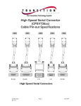
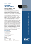
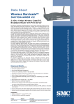
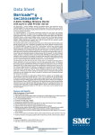
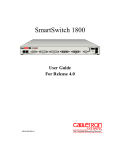
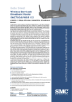
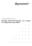
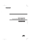
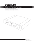
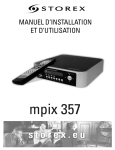
,QVWDOODWLRQ
6HWXS
*XLGH
The Complete Networking Solution TM
Cabletron Systems reserves the right to make changes in specifications and other information contained in this document without prior notice. The reader should in all cases consult Cabletron
Systems to determine whether any such changes have been made.
About This Manual
Terminology and Conventions
The hardware, firmware, and/or software described in this manual is subject to change without
notice.
This typeface represents general text. This typeface represents computer input and
output.
IN NO EVENT SHALL CABLETRON SYSTEMS BE LIABLE FOR ANY INCIDENTAL,
INDIRECT, SPECIAL, OR CONSEQUENTIAL DAMAGES WHATSOEVER (INCLUDING
BUT NOT LIMITED TO LOST PROFITS) ARISING OUT OF OR RELATED TO THIS
MANUAL OR THE INFORMATION CONTAINED IN IT, EVEN IF CABLETRON SYSTEMS
HAS BEEN ADVISED OF, KNOWN, OR SHOULD HAVE KNOWN, THE POSSIBILITY OF
SUCH DAMAGES.
This symbol points to an informational note relating to the text, table, or figure that
immediately precedes or follows it.
This symbol and text identifies a cautionary note, the content of which
is more critical to heed than an informational note.
Copyright 1997, 1998 by Cabletron Systems, Inc. All rights reserved. Printed in the United States
of America. Order Number: FRX6-INST-DOC.
Also see third-party software copyrights in the Netlink FRX4000 and FRX6000 User
Guide.
Netlink is a trademark of Cabletron Systems, Inc. All other product designations are
the property of their respective owners.
References to keyboard keys appear as "[N]", where “N” is a specific key:
Screen displays are provided to show the general appearance of actual screens. They are only
examples—they do not necessarily represent an operational system.
Related Documents
A copy of the Netlink FRX4000 and FRX6000 User Guide should always be on site at each
FRX6000. Copies of this and other Cabletron documents can be ordered from Cabletron Systems
or your local distributor of Cabletron products.
Statements of Compliance
FCC
The equipment provided by Cabletron Systems, Inc. and documented in this manual has been tested
and found to comply with the limits for a Class A digital device, pursuant to Part 15 of the FCC
Rules. These limits are designed to provide reasonable protection against harmful interference
when the equipment is operated in a commercial environment.
This equipment generates, uses, and can radiate radio frequency energy and, if not installed and
used in accordance with the installation manual, may cause harmful interference to radio communications. Operation of this equipment in a residential area is likely to cause harmful interference,
in which case the user will be required to, at his/her own expense, take the necessary measures to
eliminate the interference.
To ensure compliance with the Class A FCC limits, use only shielded cables with this equipment.
Any cable installed above a ceiling or below a floor must be of a material and construction
approved by UL for that application.
DOC (Canada)
This digital apparatus does not exceed the Class A limits for radio noise emissions from digital
apparatus set out in the Radio Interference Regulations of the Canadian Department of Communications.
Le present appareil numerique n'emet pas de bruits radioelectriques depassant les limits applicables
aux appareils numeriques de la class A prescrites dans le Reglement sur le brouillage radioelectrique edicte par le ministere des Communications du Canada.
Installation & Setup Guide
i
ii
FRX6000
Overview of Installation and Setup
Installation and Setup Procedure
When a Netlink™ FRX6000 is ordered, the customer and sales representative
decide on the required components (cards, cables, etc.). Cards and software are
then installed before the node is shipped. This document describes the steps to
be taken at the customer site to set up an FRX6000.
Set Up the Device
1. Unpack and inspect the equipment. If there is evidence of physical
damage, contact the shipper. If parts are missing, contact your sales representative.
The basic steps are as follows:
2. Set up the equipment, noting the site requirements listed earlier in this
chapter. Make sure the voltage selection switch (shown in Figure 1) is set
correctly.
1. Set up the hardware – Unpack and set up the node and any peripheral
equipment (keyboard, monitor/terminal, etc.). Connect all cables.
For guidance in placing equipment, standard cable lengths are:
Power cables = 5 feet
User interface cables = 5 feet
Auxiliary Console cables = 5 feet
VGA monitor-to-node cable = 4 feet
RLP to I/O box cable = 4 feet
2. Configure the video device – If using an ASCII terminal, set the operating
parameters. If using a VGA monitor, reconfigure an FRX6000 software
file.
3. (Only if the node has a Token Ring card) Configure the Token Ring card
if you need to change the default settings.
4. Check for Proper Operation – Switch on the node and any peripherals, and
check for proper operation.
5. Configure database records (described in the Netlink FRX4000 &
FRX6000 User Guide).
Power Switch
COM2 VGA Port LPT1 COM1
RLPs
Site Requirements
Environment: 41–104o F (5-40o C) and 20–80% humidity, non-condensing.
An AC power outlet of the appropriate voltage (115 or 230 VAC) must be
located within six feet of the device.
For adequate air flow, allow at least six inches of clearance at the rear and at
least two inches at the sides, front, and top. Provide enough space in the rear to
allow installation or removal of cables without moving the unit.
For reference, the chassis dimensions are:
In.: 19w, 16.9d, 7.0h (front panel is 19w)
Cm: 48.3w, 42.9d, 17.8h (front panel is 48.3w)
Power
Cable
Connector
Hardware Requirements
Figure 1
Although a keyboard and video device are not necessary for normal operation,
they are required for initial configuration. An FRX6000 can use an ASCII terminal or VGA monitor. The software is configured for an ASCII terminal with
a speed of 9600 bits per second. If you will be using a VGA monitor, or a terminal with a speed other than 9600 bps, you must connect a keyboard and VGA
monitor to the node, in order to rerun part of the FRX6000 software installation
procedure to change the configuration. (Each FRX6000 is shipped with cabling
to allow connection to an ASCII terminal or PC with terminal emulation)
Installation & Setup Guide
Voltage
Selection
Switch
1
LAN Adapter
Keyboard Connector
Rackmount Chassis, Rear View
The combinations of RLPs and LAN adapters might vary from
what is shown.
LAN adapter connectors are shown in Figure 2.
2
FRX6000
Ethernet
Token Ring
Cable
Service
Clamp
Loop
Retaining Screw
RLP Cable
RJ45
DB9F
DB15F
RJ45
BNC
I/O Box
Support Rails
Figure 2
LAN Card Connectors
Interface Cables
Cable Tie
3. Assuming the node will be mounted in a rack, it can be secured to slides,
or set on a fixed or slide-out shelf. The node can also be mounted directly
to the cabinet frame, but this makes access difficult.
Do not support a rack-mounted node only in the front.
It must be supported at both front and rear.
Figure 3
Rack-Mounted I/O Boxes
In the above example, both Line Interface Cards (LICs) on the RLP
are 4-port LICs (V.35, RS-232, or RS-422). A T1 or E1 LIC includes
an RJ45 adapter instead of an RLP cable and I/O box. (The T1/E1
cable is not supplied.)
4. Plug all cables into the appropriate connectors at the rear of the FRX6000,
and tighten the retaining screws on each cable connector that has them. (It
does not matter which end of an RLP cable plugs into the RLP.) Figure 1
shows the connectors on the rear of the chassis, and Figure 3 shows some
cable retaining screws.
Table 1
5. Plug the RLP cables into their associated I/O boxes and tighten the
retaining screws. If the assembly is being rack mounted, attach the I/O
boxes and cables as shown in Figure 3, using the hardware provided.
Leave a 24–36 inch service loop in each cable between the mounting rails
and the rear of the node, to allow the unit to be pulled forward.
WAN Port Interface Cables
Cable Type
Cabletron Part Number
V.35 DTE
FRX-V35DTE-CAB 1
FRX-V35DCE-CAB
FRX-232DTE-CAB
FRX-232DCE-CAB
FRX-449DTE-CAB
FRX-449DCE-CAB
FRX-X21DTE-CAB
FRX-X21DCE-CAB
V.35 DCE
RS-232 DTE
RS-232 DCE
RS-449 DTE
RS-449 DCE
X.21 DTE
X.21 DCE
* One V.35 DTE cable is shipped as standard equipment with each FRX6000.
Installation & Setup Guide
3
4
FRX6000
DCE cables have female connectors at the user end, and DTE
cables have male connectors.
PC
FRX6000
Configure the Video Device
Follow the appropriate procedure to configure the FRX6000 to operate with an
attached Auxiliary Console (ASCII terminal) or VGA monitor.
A VGA monitor may be necessary even if you are configuring the
node to operate with an ASCII terminal. See step 1 under
"Auxiliary Console."
Cabletron Cable FRX-PC-CAB, DB9S to DB9S
Figure 5
Auxiliary Console Cabling Example 2
Auxiliary Console
This feature allows an FRX6000 to be controlled from an asynchronous
(ASCII) terminal connected—directly or via modems—to the node's COM1
serial port.
ASCII Terminal
FRX6000
The following items are shipped with each FRX6000, to allow for different
methods of connecting an auxiliary console:
●
●
●
Cable, DB9S to DB9S, for connecting the node's COM1 port directly to
a PC with software emulating an ASCII terminal.
Adapter, DB9P to DB25S, for connecting the node directly (via the
above cable) to an ASCII terminal.
Cable, DB9S to DB25P, for connecting an ASCII terminal via modem
to the COM1 port.
Cabletron Cable,
FRX-MOD-CAB,
DB9S to DB25P
Figure 6
Figure 4 through Figure 6 show the cabling configurations.
Auto-answer Modems
RS-232 Cable
Auxiliary Console Cabling Example 3
ASCII Terminal
Follow this procedure to set up the auxiliary console:
FRX6000
Cabletron Cable FRX-PC-CAB,
DB9S to DB9S
Figure 4
1. If the terminal's speed is 9600 bps, go to step 11. If the speed is 1200,
2400, or 4800 bps, you must reconfigure the FRX6000 software, which
requires a VGA monitor (and keyboard). Connect the monitor to the VGA
port on the FRX6000 (see Figure 1) and plug the keyboard cable into the
keyboard connector.
2. Plug the FRX6000 and VGA monitor power cables into the appropriate
power source, then switch the monitor on.
Cabletron Adapter FRX-9/25-ADAP,
DB9P to DB25S
3. Insert the FRX6000 System Disk into the node's drive A and switch the
node on.
Auxiliary Console Cabling Example 1
4. A message concerning LAN card configuration will be displayed. When
prompted: Strike any key when ready, press [Enter].
5. When asked: Will you be using an Async terminal to configure your
FRX6000?, press [Y].
Installation & Setup Guide
5
6
FRX6000
VGA Monitor
6. When prompted for a terminal speed, type the line speed (in bits per
second) of the attached terminal ( 1200, 2400, or 4800) and press [Enter].
1. Connect the monitor to the VGA port on the FRX6000 (see Figure 1) and
plug the keyboard cable into the keyboard connector.
7. When asked: Are you changing only the Async console or LAN adapter configuration?, press [Y].
2. Plug the FRX6000 and VGA monitor power cables into the appropriate
power source, then switch the monitor on.
8. You will be asked: How many LAN cards have you installed (0-2)?
3. Insert the FRX6000 System Disk into the node's drive A and switch the
node on.
Even though you are changing only the async terminal setup,
you must redo the LAN card setup (if cards are installed), since
changing the terminal setup writes over a file that contains the
specifications for the terminal and the LAN cards.
4. A message concerning LAN card configuration will be displayed. When
prompted: Strike any key when ready, press [Enter].
5. When asked: Will you be using an Async terminal to configure your
FRX6000?, press [N].
If none, press [Enter] to accept the default of 0, then go to step 10. Otherwise, enter the number of LAN cards and go to step 9.
6. When asked: Are you changing only the Async console or LAN adapter configuration?, press [Y].
9. You will be asked to specify the type of LAN card 0. (LAN cards are numbered 0 and 1.) Enter the appropriate number from the choices:
7. You will be asked: How many LAN cards have you installed (0-2)?
3 – SMC EtherCard Plus Elite16
4 – IBM Token Ring Card
5 – SMC Token Ring Card
Even though you are changing only the async terminal setup,
you must redo the LAN card setup (if cards are installed), since
changing the terminal setup writes over a file that contains the
specifications for the terminal and the LAN cards.
The IBM card is not currently offered, but is supported by the
software for some functions. Discuss your configuration
requirements with Cabletron Systems Technical Support if a
node contains an IBM card.
If none, press [Enter] to accept the default of 0, then go to step 9. Otherwise, enter the number of LAN cards and go to step 8.
8. You will be asked to specify the type of LAN card 0. (LAN cards are numbered 0 and 1.) Enter the appropriate number from the choices:
If only one LAN card is installed, go to step 10. If two are installed, repeat
step 9 for the second card, then go to step 10.
3 – SMC EtherCard Plus Elite16
4 – IBM Token Ring Card
5 – SMC Token Ring Card
10. Remove the diskette, switch the FRX6000 and VGA monitor off, and disconnect the monitor from the FRX6000's VGA port.
11. Install the console and cabling as shown in Figure 4 through Figure 6.
The IBM card is not currently offered, but is supported by the
software for some functions. Discuss your configuration
requirements with Cabletron Systems Technical Support if a
node contains an IBM card.
12. Set up the terminal as described in the user's manual for that terminal, with
the terminal should be set to:
Autowrap,
Application Keypad
No newline
No break
Tab every 8 columns 8 bits no parity
Application cursor key
VT100 (ASCII) mode
If only one LAN card is installed, go to step 9. If two are installed, repeat
step 8 for the second card, then go to step 9.
9. Remove the diskette from the drive.
Installation & Setup Guide
7
8
FRX6000
Configure the Token Ring Card
Node Name=
If the node has a Token Ring card, it is configured for a speed of 16 MB/sec and
UTP (unshielded twisted pair) cable. If you wish to change either setting,
follow this procedure:
Port Status Display (Page 1)
L P
Type
PPS Conn#
State
L P Type PPS Conn#
State
1. Boot the node with a DOS system disk.
2. At the A:> prompt, insert the SMC SuperDisk, then type ezstart and press
[Enter]. The EZStart main menu will be displayed, showing the current
configuration of any installed SMC Token Ring adapter(s).
3. If there are two Token Ring cards installed, select the adapter number
(Select Adapter).
4. Select Custom, then change the Network Interface setting(s) as desired.
F1: Login
5. When finished reconfiguring the card(s), remove the diskette.
Check for Proper Operation
Figure 7
This procedure requires a video device connected to the node.
1. Switch the node on and watch the power-up and boot messages for signs
of problems. A typical power-up sequence display will contain BIOS
copyright information followed by a System Configuration table: disk
drive types, base and extended memory, etc. A typical boot sequence will
include copyright information, debug messages, and messages tracking
the loading of RLPs.
Port Status Display
2. To log in, press [F1] at the Port Status Display, then enter the FRX6000
password when requested. (The default password when the software is
installed is NETLINK.) Once the password has been entered, the Main
Menu (Figure 8) will be displayed.
If the entered password is not correct, the Port Status Display
will reappear; if no password is entered, the Port Status Display
will reappear after a one minute timeout.
Watch power-up and boot messages carefully—some errors will cause a
pause, but otherwise will not interfere with the boot process, and the only
way you will know there is a problem is to see the message as it is displayed. Be aware of messages that say: Loading LP "n" - RLP. Such a
message should appear for each installed RLP.
Some messages are written to a file called BOOTRPT.TXT.
Once the FRX6000 software is running, this file can be displayed. (See "Displaying Boot-up Information" on pge 11.)
Once the software has loaded, a screen similar to the following will be displayed.
Installation & Setup Guide
9
10
FRX6000
4. Display the new boot data, and compare it to the previous data. This will
show whether the problem was fixed. Also, a problem that occurred
during the previous boot-up will often be cleared up by re-booting.
Node Name=
Netlink FRXSeries Version "n.n.n.n"
MAIN MENU
A Configuration
Questions?
B Operations
If you have questions or problems, please contact Cabletron Systems Technical
Support at:
C Status Displays
D Events
Phone: 603-332-9400
Fax:
603-337-3075
E-mail: [email protected]
E Statistics
F Reports
Option:
Figure 8
Main Menu
3. From here, configure the database as described in the User Guide, or, if
there was some problem, go to "Displaying Boot-up Information."
Displaying Boot-up Information
As the node boots, screen information tracks the loading of RLPs, verifies configuration file format, and displays any errors. This data is displayed only until
the FRX6000 software is running; however, most of it is saved in a file named
BOOTRPT.TXT, and the operator can later display it in a report.
This can be used as a tool to verify that startup of the node proceeded without
errors, or to remind an FRX6000 operator of the number or RLPs in the node.
If there is an error reported, the data may aid in fixing the problem.
To display the data from the current boot-up, press [C] at the Reports Menu (or
[F], then [C] from the Main Menu). To display the data from the previous bootup (saved in a file called BOOTBAK.TXT) , press [D] at the Reports Menu (or
[F], then [D] from the Main Menu).
BOOTRPT.TXT and BOOTBAK.TXT can be used as follows:
1. Display and review the data from the "current" boot of the node.
2. Address any reported problems.
3. Re-boot the node. (This copies the previous boot data to a backup file.)
Installation & Setup Guide
11
12
FRX6000
The Complete Networking Solution TM
Document number 09-41-06-144-02