1
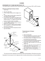
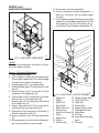
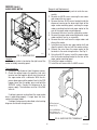
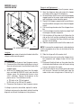
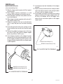
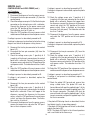
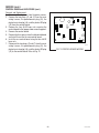
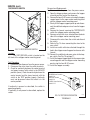
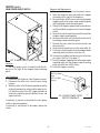
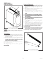
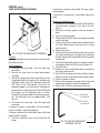
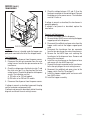
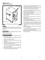
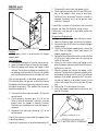
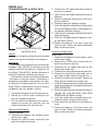
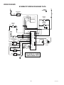
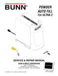
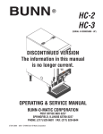
BUNN
®
POWDER
™
AUTO FILL
For CDS-2 & 3
OPERATING & SERVICE MANUAL
BUNN-O-MATIC CORPORATION
POST OFFICE BOX 3227
SPRINGFIELD, ILLINOIS 62708-3227
PHONE: (217) 529-6601 FAX: (217) 529-6644
29793.0000C 08/02 ©1999 Bunn-O-Matic Corporation
www.bunnomatic.com
INTRODUCTION
This equipment supplies a liquid mix to the hoppers on the CDS-2 or 3 dispensers. It is for indoor use only on
a sturdy counter or shelf.
BUNN-O-MATIC COMMERCIAL PRODUCT WARRANTY
Bunn-O-Matic Corp. (“BUNN”) warrants equipment manufactured by it as follows:
1) All equipment other than as specified below: 2 years parts and 1 year labor.
2) Electronic circuit and/or control boards: parts and labor for 3 years.
3) Compressors on refrigeration equipment: 5 years parts and 1 year labor.
4) Grinding burrs on coffee grinding equipment to grind coffee to meet original factory screen sieve analysis: parts and labor for 3 years
or 30,000 pounds of coffee, whichever comes first.
These warranty periods run from the date of installation BUNN warrants that the equipment manufactured by it will be commercially
free of defects in material and workmanship existing at the time of manufacture and appearing within the applicable warranty period.
This warranty does not apply to any equipment, component or part that was not manufactured by BUNN or that, in BUNN’s judgment,
has been affected by misuse, neglect, alteration, improper installation or operation, improper maintenance or repair, damage or
casualty. This warranty is conditioned on the Buyer 1) giving BUNN prompt notice of any claim to be made under this warranty by
telephone at (217) 529-6601 or by writing to Post Office Box 3227, Springfield, Illinois 62708-3227; 2) if requested by BUNN, shipping
the defective equipment prepaid to an authorized BUNN service location; and 3) receiving prior authorization from BUNN that the
defective equipment is under warranty.
THE FOREGOING WARRANTY IS EXCLUSIVE AND IS IN LIEU OF ANY OTHER WARRANTY, WRITTEN OR ORAL, EXPRESS OR
IMPLIED, INCLUDING, BUT NOT LIMITED TO, ANY IMPLIED WARRANTY OF EITHER MERCHANTABILITY OR FITNESS FOR A
PARTICULAR PURPOSE. The agents, dealers or employees of BUNN are not authorized to make modifications to this warranty or to
make additional warranties that are binding on BUNN. Accordingly, statements by such individuals, whether oral or written, do not
constitute warranties and should not be relied upon.
If BUNN determines in its sole discretion that the equipment does not conform to the warranty, BUNN, at its exclusive option while the
equipment is under warranty, shall either 1) provide at no charge replacement parts and/or labor (during the applicable parts and labor
warranty periods specified above) to repair the defective components, provided that this repair is done by a BUNN Authorized Service
Representative; or 2) shall replace the equipment or refund the purchase price for the equipment.
THE BUYER’S REMEDY AGAINST BUNN FOR THE BREACH OF ANY OBLIGATION ARISING OUT OF THE SALE OF THIS EQUIPMENT,
WHETHER DERIVED FROM WARRANTY OR OTHERWISE, SHALL BE LIMITED, AT BUNN’S SOLE OPTION AS SPECIFIED HEREIN, TO
REPAIR, REPLACEMENT OR REFUND.
In no event shall BUNN be liable for any other damage or loss, including, but not limited to, lost profits, lost sales, loss of use of
equipment, claims of Buyer’s customers, cost of capital, cost of down time, cost of substitute equipment, facilities or services, or any
other special, incidental or consequential damages.
INITIAL SET-UP
1. Locate the hopper elbow with slide gate, whipping chamber with dispense tip, and mixing chamber located in
the Powder Auto-Fill hopper.
2. Assemble the hopper elbow with slide gate to the hopper.
3. Assemble the whipping chamber with dispense tip to the whipper receptacle on the Powder Auto-Fill.
4. Assemble the mixing chamber to the whipping chamber and water inlet on the Powder Auto-Fill.
5. Locate the door assembly and door mounting hardware taped to the back of the door assembly.
6. Remove the door mounting hardware from the bag and set it aside
7. Carefully lift the door and locate the lamp cord connector.
8. Connect the door lamp cord connector to the receptacle located on the top of the Powder Auto-Fill.
9. Carefully rotate the support arms on the back of the door so they are roughly perpendicular to the rear of the
door.
2
29793 080102
10. Slowly feed the door support arms through the slots located on the front of the Powder Auto-Fill.
11. Continue to slowly feed the door support arms through the slots until the magnet strikes on the back of the
door engage the magnets on the Powder Auto-Fill.
12. Locate the #8-32 x .375" truss head screws and brass spacers set aside earlier.
13. Place one brass spacer on each screw.
14. Insert one screw/spacer assembly through the door hinge, locating the spacer inside the hinge bushing and
threading the screw into the hinge mount on the Powder Auto-Fill cover. Repeat for other side.
15. Install PAF level probe (BOM #29728.1000) by sliding it into the notched area at the top rear of the CDS hopper.
The probe should be firmly seated in the notch and touching the contact pin protruding from the front of the
CDS cooling drum mount.
NOTE: At this point, it is important that the CDS machine is fully assembled according to the instructions outlined
in the CDS Operating and Service Manual.
16. Place the assembled Powder Auto-Fill on top of a hopper of a fully assembled CDS machine, taking care to align
the Powder Auto-Fill guide rails over the rollers on the CDS.
17. Connect the Powder Auto-Fill power cord to the outlet located on the CDS auger motor cover.
18. Attach a flexible water line to the .25" flare fitting on the back panel of the Powder Auto-Fill.
NOTE: A water strainer assembly (BUNN-O-MATIC #23820.1000) should be installed in line prior to the flexible
water line.
USER NOTICES
Carefully read and follow all notices on the equipment and in this manual. They were written for your protection.
All notices are to be kept in good condition. Replace any unreadable or damaged labels.
00656.0000
00986.0000
Push back until fully latched
before removing or manually
filling chilled product hopper.
34561.0000
3
29793 080102
OPERATING INSTRUCTIONS
9. After checking the CDS and Powder Auto-Fill setup, the 5 minute refill fault may be cleared by simply
opening and closing the Powder Auto-Fill door.
10. Once the product level in the CDS covers the auger,
make the following switch settings at the CDS
control panel:
a) AUGER - "1".
b) ICE/OFF/NO ICE - "ICE" or "NO ICE" as appropriate
for the granita product.
11. From this point onward, the Powder Auto-Fill will
continue to automatically refill the CDS hopper,
maintaining the CDS product at an approximate 2
gallon level.
12. When the Powder Auto-Fill powder level falls low,
the door lamp will cycle ON and OFF, but will
continue to dispense product for a preset period.
When this period expires, the Powder Auto-Fill will
continue to cycle the door lamp ON and OFF and will
stop dispensing product.
13. To clear the low product fault, simply refill the
powder as follows:
a) Open the Powder Auto-Fill door.
b) Close the hopper slide gate.
c) Remove the product hopper.
d) Refill the product hopper with powdered granita
mix.
e) Replace the hopper.
f) Push the slide gate on the hopper ejector elbow
to the OPEN position.
g) Close the Powder Auto-Fill door.
1. On the CDS control panel, make the following
switch settings:
a) POWER- "ON"
b) DAY/NIGHT- "DAY"
2. Pull the Powder Auto-Fill fully forward on its support rails and open the door.
3. Fill the Powder Auto-Fill product hopper as follows:
a) Pull the slide gate closed on the Powder Auto-Fill
product hopper elbow and remove the hopper from
the Powder Auto-Fill.
b) Remove the lid from the product hopper and fill
the hopper with a powdered granita mix.
c) Install the product hopper into the Powder AutoFill. Insure hopper is fully seated behind retainer
plates.
d) Push the slide gate on the hopper ejector elbow
to the open position.
4. Place the ON/OFF switch at the Powder Auto-Fill
whipper panel to "ON".
5. After allowing 5 seconds for the Powder Auto-Fill to
initialize, observe the door lamp. The door lamp
should not be lit. If the door lamp is lit, consult the
fault list located on the decal placed on the back of
the door. Clear the fault before proceeding.
NOTE: If the Powder Auto-Fill is being used for the first
time with the selected granita mix, perform an adjustment as described in ADJUSTMENTS.
6. Close the Powder Auto-Fill door and observe the
following:
a) The door lamp lights steadily.
b) The Powder Auto-Fill begins dispensing liquid
granita product.
7. The Powder Auto-Fill will continue to fill the CDS
product hopper until the liquid level in the CDS
hopper reaches the product level probe or for 5
minutes, which ever occurs first.
8. If the Powder Auto-Fill fails to fill the CDS hopper in
5 minutes, the following will occur:
a) The Powder Auto-Fill will stop dispensing product.
b) The door lamp will flash 4 times about every 2
seconds.
4
29793 061599
ADJUSTMENTS
When using the Powder Auto-Fill with a new powdered granita mix, follow the procedure outlined below to
adjust the Powder Auto-Fill to produce the correct recipe.
1. Determine the mix ratio of powdered granita mix.
Convert the recipe so that it is expressed in terms
of weight units [grams (g), dry ounces (oz), or
pounds (lbs)] of powdered granita mix to fluid
ounces (fl.oz.) of water [1 gallon (gal) = 128 fl.oz.;
1 liter (l) = 33.8 fl.oz.].
2. The delivery rate of the water ingredient is factory
preset to 1 fl.oz. per second. Therefore, it is only
necessary to adjust the delivery rate of the powdered granita mix. Adjustment is accomplished as
follows:
a) Place the Powder Auto-Fill on top of a fully
assembled CDS taking care to align the Powder
Auto-Fill guide rails over the rollers on the CDS
guide rails.
b) Connect the Powder Auto-Fill power cord to the
outlet located on the CDS auger motor cover.
c) Attach a flexible water line to the .25" flare fitting
on the back panel of the Powder Auto-Fill.
i) Remove the hole plug on the whipper panel.
Using a screwdriver, set potentiometer to approximately mid range.
j) Remove the mixing chamber from the Powder
Auto-Fill and place a small container, such as a cup,
under the product hopper ejector elbow.
k) Push the slide gate on the product hopper ejector
elbow to the OPEN position.
l) Momentarily set the TEST/SERVICE switch on the
whipper panel to the TEST position.
m) The hopper motor will run and dispense powdered granita mix for 10 seconds.
n) After the Powder Auto-Fill has finished the 10
second throw test, weigh the dispensed product.
o) Determine the dispense rate of the powdered
product (weight units per second) by dividing the
measured weight by 10.
p) Compare the measured dispense rate with the
mix ratio in step 1.
q) Adjust the MIN/MAX control clockwise to increase the dispense rate or counterclockwise to
decrease the dispense rate of the powdered granita
mix.
r) Repeat steps l through q as necessary until
proper mix ratio is achieved.
s) Replace the mixing chamber removed in step j.
Replace hole plug.
3. Once the mix ratio has been adjusted, the Powder
Auto-Fill can be run with the door open to allow the
user to catch dispensed product for brix testing as
follows:
a) Hold a container under the dispense tip of the
Powder Auto-Fill.
b) Hold the TEST/SERVICE switch on the whipper
panel to the SERVICE position.
c) When the container is filled to the desired level,
release the TEST/SERVICE switch.
d) Measure the brix using the appropriate measuring device.
e) Remove the hole plug. Using a screwdriver,
adjust the potentiometer clockwise to increase the
brix or counterclockwise to decrease the brix of the
product. Replace the hole plug.
NOTE: A water strainer assembly (BUNN-O-MATIC
#23820.1000) should be installed in line prior to the
flexible water line.
d) On the CDS control panel, make the following
switch settings:
i) POWER- "ON"
ii) DAY/NIGHT- "DAY"
e) Pull the Powder Auto-Fill fully forward on its
support rails
f) Fill the Powder Auto-Fill product hopper as follows:
i) Pull the slide gate closed on the Powder AutoFill product hopper elbow and remove the product
hopper from the Powder Auto-Fill.
ii) Remove the lid from the product hopper and
fill the hopper with a powdered granita mix.
iii) Install the product hopper into the Powder
Auto-Fill.
g) Place the ON/OFF switch at the Powder Auto-Fill
whipper panel to "ON".
h) After allowing 5 seconds for the Powder Auto-Fill
to initialize, observe the door lamp on the whipper
panel. The door lamp should not be lit. If the door
lamp is lit, consult the fault list and clear the fault
before proceeding.
5
29793 061599
CLEANING
RECOMMENDED DAILY CLEANING AND MAINTENANCE TIPS
This should be done in conjunction with the recommended weekly cleaning of your CDS-2 or CDS-3 machine.
Removing and cleaning the whipper chamber
(once a day):
1. Open the cabinet door.
2. Pull the mixing chamber out of the whipper chamber.
3. Twist the whipper chamber clockwise and pull it off
the whipper chamber receptacle.
4. Pull the frother off the motor shaft. Notice the flat
keyway on the shaft and the matching keyway
inside the frother. It is important that these two
keyways are lined up when reassembling.
5. Twist the whipper chamber receptacle clockwise
and pull it off the motor shaft.
6. Slip the O-ring off the whipper chamber receptacle.
7. Wash components in a mild solution of dish detergent using a bristle brush.
8. Rinse thoroughly and allow to dry before reinstalling in the machine.
Mixing Chamber
Whipper Chamber
Receptacle
O-ring
Frother
Dispense Tip
Whipper Chamber
Thorough cleaning of the hopper
(once a week):
Wiper Blade
Shaft
Wiper Blade
1. Open the cabinet door.
2. Remove the hopper/base assembly from the cabinet, remove the cover and empty the contents.
3. Pull the ejector elbow off the hopper base; remove
the slide gate from the ejector elbow.
4. Remove the wiper blade and drive gear by removing
the retaining ring from the wiper blade shaft.
5. Remove the auger by pulling it out of the front
hopper base.
6. Remove the auger drive shaft by removing the
retaining clip from the auger drive shaft.
7. Wash components in a mild solution of dish detergent using a bristle brush when needed.
8. Rinse and dry each item thoroughly before reassembling.
Wiper Drive Gear
Retaining
Clip
Hopper Base
Auger Drive
Shaft
Auger Drive
Bracket
Retaining
Ring
Auger
Ejector Elbow
Slide Gate
NOTICE
The cleaning instructions noted above are for nondairy sugar based food products. When dispensing any other
food product, the cleaning cycle for the whipping chamber assembly and ejector elbow must be performed daily.
6
29793 061599
FAULT LIST
Door Lamp
Fault
ON
Normal operation - Powder Auto-Fill ready to
dispense
Flashes ON/OFF at 50% duty cycle
Low product level in Powder Auto-Fill hopper
Two flashes about every 2 seconds
CDS/Powder Auto-Fill probe circuit open
Three flashes about every 2 seconds
Powder Auto-Fill hopper not in place
Four flashes about every 2 seconds
CDS refill exceeded 5 minutes
OFF
Door not closed
7
29793 061599
TROUBLESHOOTING
A troubleshooting guide is provided to suggest probable causes and remedies for the most likely problems
encountered. If the problem remains after exhausting the troubleshooting steps, contact the Bunn-O-Matic
Technical Service Department.
•
•
•
•
•
•
•
Inspection, testing, and repair of electrical equipment should be performed only by qualified service personnel.
All electronic components have 120 volt ac and low voltage dc potential on their terminals. Shorting of
terminals or the application of external voltages may result in board failure.
Intermittent operation of electronic circuit boards is unlikely. Board failure will normally be permanent. If an
intermittent condition is encountered, the cause will likely be a switch contact or a loose connection at a
terminal or crimp.
Solenoid removal requires interrupting the water supply to the valve. Damage may result if solenoids are
energized for more than ten minutes without a supply of water.
The use of two wrenches is recommended whenever plumbing fittings are tightened or loosened. This will help
to avoid twists and kinks in the tubing.
Make certain that all plumbing connections are sealed and electrical connections tight and isolated.
Keep away from combustibles.
WARNING – •
•
•
•
PROBLEM
Exercise extreme caution when servicing electrical equipment.
Unplug the dispenser when servicing, except when electrical tests are specified.
Follow recommended service procedures
Replace all protective shields or safety notices
PROBABLE CAUSE
REMEDY
CDS and Powder Auto-Fill do not 1. CDS power cord disconnected or Check that the power cord is conrun - Main power indicator on CDS main power switch in 0 position.
nected to proper electrical source
drawer front OFF
and that the CDS main power switch
is in the 1 position.
Product level in CDS is lower than 1. The CDS DAY/NIGHT switch in the
level Probe - CDS running; Powder NIGHT position.
Auto-Fill door lamp is OFF
2. The CDS DAY/NIGHT timer in the
NIGHT position.
1. The CDS DAY/NIGHT switch
should be in the DAY position.
2. Reprogram the CDS DAY/NIGHT
timer.
3. Powder Auto-Fill power cord dis- 3. Check that the Powder Auto-Fill is
connected.
plugged into the back of the CDS
auger motor cover.
4. Powder Auto-Fill main power 4. Select the ON position of the main
switch in OFF position.
power switch.
5. Powder Auto-Fill door is open.
5. The Powder Auto-Fill door should
be closed securely.
Product level in CDS is lower than 1. Low product in Powder Auto-Fill. Remove hopper and fill with powlevel Probe - CDS running; Powder
dered mix.
Auto-Fill door lamp flashes ON and
OFF
8
29793 061599
TROUBLESHOOTING (cont.)
PROBLEM
PROBABLE CAUSE
Product level in CDS is lower than 1. Powder Auto-Fill not pulled comlevel Probe - CDS running; Powder pletely forward.
Auto-Fill door lamp flashes two times
2. CDS level probe misaligned.
REMEDY
1. Check that the Powder Auto-Fill is
pulled completely forward until the
guide rails roll into the indented position.
2. Position the CDS level probe so
that it is located in the notch of the
CDS hopper and touching the contact protruding from the front of the
CDS cooling drum mount.
Product level in CDS is lower than 1. Powder Auto-Fill hopper not inlevel Probe - CDS running; Powder stalled.
Auto-Fill door lamp flashes three
times
2. Powder Auto-Fill hopper not installed properly.
1. Install the Powder Auto-Fill hopper.
Product level in CDS is lower than 1. Refill time exceeded five minutes.
level Probe - CDS running; Powder
Auto-Fill door lamp flashes four times
Check that the SERVICE switch is
released or reset by opening and
closing the Powder Auto-Fill door.
The CDS product tastes "watery" or 1. Improper adjustment of product
"sugary"
mix ratio.
Adjust the product mix ratio per instructions in Powder Auto-Fill Adjustment. See page 5.
Powder Auto-Fill dispenses dry prod- 1. Powder Auto-Fill not connected to
uct only - dry powder build-up in water source.
mixing and whipper chambers
1. Connect the Powder Auto-Fill to a
20 to 90 psi (138 to 620 kPa)water
source.
2. Reposition the Powder Auto-Fill
hopper.
2. Water source turned off.
2. Turn water source on.
3. Water line obstructed.
3. Remove obstruction.
9
29793 011500
TROUBLESHOOTING (cont.)
PROBLEM
PROBABLE CAUSE
Powder Auto-Fill will not dispense 1. No water
product
REMEDY
Water lines and valves to the dispenser must be open and free of
obstructions.
2. No power or incorrect voltage to
the dispenser.
Check that the power cord is connected to the CDS dispenser and for
voltage from the CDS dispenser.
3. Dispense Solenoid Valve
Refer to Service- Dispense Solenoid
Valve for testing procedures. See
page 32
4. Control Board and Probe
Refer to Service- Control Board and
Probe for testing procedures. See
page 18
5. Auger Drive
Refer to Service- Auger Drive for
testing procedures. See page 13
6. Transformer
Refer to Service- Transformer for
testing procedures. See page 26
7. Water Strainer (Optional)
A) Direction of flow arrow must be
pointing towards dispenser.
B) Remove the strainer and check
for obstructions. Clear or replace.
Dripping from dispense tip
1. Dispense Solenoid Valve
Remove dispense valve and clear
any obstructions. Rebuild or replace
the valve if necessary. Seepage 32
Water flows continuously
1. Control Board and Probe
Refer to Service- Control Board and
Probe for testing procedures. See
page 18
2. Dispense Solenoid Valve
Refer to Service- Dispense Solenoid
Valve for testing procedures. See
page 32
10
29793 061599
TROUBLESHOOTING (cont.)
PROBLEM
Product overflows CDS hopper
Weak product
PROBABLE CAUSE
1. Control Board and Probe
REMEDY
2. Dispense Solenoid Valve
Refer to Service- Dispense Solenoid
Valve for testing procedures. See
page 32
1. Whipper Motor
Refer to Service- Whipper Motor for
testing procedures. See page 16
2. Frother
Refer to Service- Frother for testing
procedures. See page 15
3. Dispense Solenoid Valve
Refer to Service- Dispense Solenoid
Valve for testing procedures. See
page 32
4. Auger Drive
Refer to Service- Auger Drive for
testing procedures. See page 13
5. Auger Spring
Refer to Service- Auger Spring for
testing procedures. See page 13
6. Auger Motor
Refer to Service- Auger Motor for
testing procedures. See page 14
7. Improper adjustment of product
mix ratio
Set the product mix ratio per Adjustments. See page 5
Dispenser is making unusual noises 1. Plumbing lines
Refer to Service- Control Board and
Probe for testing procedures. See
page 18
Plumbing lines should not be resting on the counter top.
A) The dispenser must be connected
to a cold water line.
2. Water supply
B) Water pressure to the dispenser
must not exceed 90 psi (620 kPa).
Install a regulator if necessary to
lower the working pressure to approximately 50 psi (345 kPa).
Display not lit
1. Lamp
Refer to Service- Lamp for testing
procedures. See page 25
2. Lamp Holder
Refer to Service- Lamp Holder for
testing procedures. See page 25
11
29793 011500
SERVICE
This section provides procedures for testing and
replacing various major components used in this dispenser should service become necessary. Refer to
Troubleshooting for assistance in determining the cause
of any problem.
WARNING - Inspection, testing, and repair of electrical
equipment should be performed only by qualified service personnel. The dispenser should be unplugged
when servicing, except when electrical tests are required and the test procedure specifically states to
plug-in the dispenser.
COMPONENT ACCESS
WARNING - Disconnect the dispenser from the power
source before the removal of any panel or the replacement of any component.
All components are accessible by opening the door,
removal of the door panel, removal of the dispenser
rear panel, hopper, hopper support plate and top wraparound cover. Refer to Fig. 1
P1891
FIG. 1 COMPONENT LOCATIONS
Contents
Auger Drive Components ...................................... 13
Auger Motor ......................................................... 14
Frother and Mixing/Whipper Chamber .................. 15
Whipper Motor ..................................................... 16
Control Board and Level Probes ........................... 18
TEST/SERVICE Switch .......................................... 21
Main Power ON/OFF Switch .................................. 22
Door Panel Assembly
Lamp Cord Assembly ..................................... 23
Lamp Cord Connector..................................... 24
Lamp Holder/Socket ....................................... 25
Transformer .......................................................... 26
Potentiometer ....................................................... 27
Hopper Level Indicator ......................................... 28
Hopper Switch ...................................................... 29
Door Switch .......................................................... 30
Pressure Regulator and Needle Valve ................... 31
Dispense Solenoid ................................................ 32
Wiring Diagrams ................................................... 33
12
29793 061599
SERVICE (cont.)
AUGER DRIVE COMPONENTS
12. Rinse and dry each item thoroughly.
13. Check for damaged or broken components, replace any if necessary and reassemble hopper
assembly.
14. Install hopper assembly in the dispenser by sliding
hopper assy on the hopper support plate (12) until
the hopper base (9) seats firmly behind the retainer plates (16) on the hopper support plate (12).
1
2
3
4
5
6
7
P1922
13
FIG. 2 AUGER DRIVE COMPONENTS
14
8
9
10
11
17
Location
The auger drive components are located in the bottom of the hopper assembly.
20
15
21
Removal, Cleaning and Replacement
1. Open the dispenser door.
2. Lift the hopper assembly over the retainer plates
(16) on hopper support plate (12) and slide hopper
assembly out the front of the dispenser.
3. Remove hopper lid (1) and empty product.
4. Pull off the ejector elbow (15) and remove the slide
gate (21).
5. Remove retainer ring (11) and washer (10) from
the bottom of the hopper base (9).
6. Remove wiper shaft (3), wiper blade (4) and wiper
drive gear (5) from the hopper base (9).
7. Remove auger wire (14) by pulling it out the front
of the hopper base (9).
8. Remove auger drive shaft (13) by removing the
retaining clip (6) from auger drive shaft.
9. Slide spacer (8) and auger drive shaft bracket (7)
off of the auger drive shaft (13).
10. Remove auger drive shaft (13) from hopper base
(9).
11. Wash components in a mild solution of dish detergent using a bristle brush when needed.
18
19
16
12
P1894
FIG. 3 AUGER DRIVE & HOPPER ASSEMBLY
12.
1. Hopper Lid
13.
2. Hopper
14.
3. Wiper Shaft
15.
4. Wiper Blade
5. Wiper Drive Gear 16.
17.
6. Retainer Clip
7. Auger Drive Bracket 18.
19.
8. Spacer
20.
9. Hopper Base
10. Washer
11. Retainer Ring
21.
13
Hopper Support Plate
Auger Drive Shaft
Auger Wire
Ejector Elbow
Hopper Retainer Plates
Auger Motor Bracket
Auger Motor
Dust Seal
Auger Motor Mounting
panel
Slide gate
29793 061599
SERVICE (cont.)
AUGER DRIVE MOTOR
Removal and Replacement:
1. Remove hopper assembly and set aside for reassembly.
2. Remove six #8-32 screws securing the rear cover
and remove the rear cover.
3. Remove the four #8-32 screws located inside the
dispenser housing on the lower right front of the
auger motor mounting panel, securing the auger
motor mounting bracket and auger motor to the
rear of the auger motor mounting panel.
4 Disconnect the wires from the auger drive motor.
5. Remove the auger motor mounting bracket, auger
motor and dust seal as an assembly.
6. Remove the dust seal from the auger motor and
discard the motor.
7. Install dust seal on the new auger motor shaft and
align the notch in the seal with the motor casting.
8. Connect the wires from the auger motor to the
terminals in the main wiring harness. See Fig. 5.
9. Using four #8-32 screws, install the auger motor,
dust seal and mounting bracket to the rear of the
auger motor mounting panel.
10. Install the hopper assembly.
11. Install the rear cover with six #8-32 screws.
P1922
FIG. 4 AUGER MOTOR
Location:
The auger motor is located on the right rear of the
motor assembly mounting panel.
Test procedures:
1. Disconnect the dispenser from the power source.
2. Check the voltage across the positive (red wire)
terminal and the negative (black wire) terminal on
the auger motor with a voltmeter. With the dispenser door open and the product level in the CDS
hopper lower than the probe, press and hold the
SERVICE switch. Connect the dispenser to the
power supply. The indication must be 4.0 to 26.5
volts dc.
If voltage is present as described, the auger motor
drive is operating properly. If auger does not turn,
replace the auger motor.
If voltage is not present as described, refer to wiring
diagrams and check wiring harness.
RED to Control
Board (J1-1)
BLK to GRN Wire
Main Harness to
Control Board (J1-7)
P1902
FIG. 5 AUGER MOTOR TERMINALS
14
29793 061599
SERVICE (cont.)
10. Slide whipper chamber receptacle with seal (6) and
O-ring (4) on to the motor shaft.
11. Rotate the receptacle with seal (6) counterclockwise until it snaps into place on the motor mounting
nuts (7).
12. Push frother (5) onto the motor shaft, making sure
the flat in the frother (5) lines up with the flat on the
motor shaft.
13. Install whipper chamber (3) on the whipper chamber receptacle (6) by twisting counterclockwise
until tabs on the whipper chamber (3) lock with the
tabs on the whipper chamber receptacle (6). Be
sure dispense port is pointing down.
14. Install dispense tip (2) into the bottom of the
whipper chamber (3).
15. Slip the mixing chamber (1) onto the mixing chamber water inlet tube far enough so the mixing
chamber (1) will seat inside the whipper chamber
(3).
16. Install hopper assembly in the dispenser by sliding
hopper firmly behind the retainer plates on the
hopper support panel.
FROTHER AND MIXING/WHIPPER CHAMBER
FIG. 6 FROTHER AND
MIXING/WHIPPER CHAMBER
P1923
Location:
The frother is located behind the dispenser door,
mounted on the front panel and inside the whipper
chamber.
Removal, Cleaning and Replacement:
1. Disconnect the dispenser from the power source.
2. Open the dispenser door and lift the front edge of
the hopper over the retainer plates on the hopper
support panel and slide the hopper assembly out
the front of the dispenser.
3. Pull the mixing chamber (1) out of the whipper
chamber (3).
4. Remove the dispense tip (2) and twist the whipper
chamber (3) clockwise and pull it off the whipper
chamber receptacle (6).
5. Pull the frother (5) off the motor shaft. Notice the
flat side on the shaft and the matching flat inside the
frother. It is important that these two flats are lined
up when reassembling.
6. Slip the O-ring (4) off the whipper chamber receptacle (6).
7. Remove the receptacle by rotating clockwise until
the receptacle clears the nuts (7) and slide off the
motor shaft.
8. Wash components in a mild solution of dish detergent using a bristle brush.
9. Rinse thoroughly and allow to dry before reinstalling in the dispenser.
9
8
7
6
5
4
1
3
2
FIG. 7 MIXING/WHIPPER CHAMBER
COMPONENTS
1.
2.
3.
4.
5.
15
Mixing Chamber
Dispense Tip
Whipper Chamber
O-Ring
Frother
6.
7.
8.
9.
P1895
Receptacle w/Seal
Nut
Slinger
Motor Assembly
29793 061599
SERVICE (cont.)
WHIPPER MOTOR
Removal and Replacement:
1. Disconnect the dispenser from the power source.
2. Open the dispenser door and remove the hopper
assembly out the front of the dispenser.
3. Remove the four #8-32 screws securing the hopper
support panel to the auger motor mounting panel
and the whipper motor mounting panel.
4. Slowly lift the hopper support panel up and disconnect the red/black and green wires from the hopper
switch.
5. Pull the mixing chamber out of the whipper chamber.
6. Twist the whipper chamber clockwise and pull it off
the whipper chamber receptacle.
7. Pull the frother off the motor shaft. Notice the flat
side on the shaft and the matching flat inside the
frother. It is important that these two flats are lined
up when reassembling.
8. Slide the receptacle with seal off of the motor shaft.
P1924
NOTE: To remove the receptacle only, rotate clockwise
until the receptacle clears the nuts and slide off of the
motor shaft.
FIG. 8 WHIPPER MOTOR
Location:
The whipper motor is located on the back side of the
whipper motor mounting panel.
9. Slide the slinger off of the motor shaft.
10. Remove the two nuts securing the whipper chamber receptacle and whipper motor to the front
panel.
11. Disconnect the black leads on the motor from the
white/red and white/brown wires of the main wiring
harness and remove the motor.
12. Install new motor on rear of front panel and secure
with two nuts. Connect the black leads from the
motor to the main wiring harness. Refer to Fig. 9
Test Procedure:
1. Disconnect the dispenser from the power source.
2. Disconnect the white/red and white/brown wires of
the main wiring harness from the black leads of the
whipper motor.
3. With the CDS hopper level lower than the probe,
press and hold the SERVICE switch and check the
voltage across the disconnected harness wires
with a voltmeter. Connect the dispenser to the
power source. The indication must be:
a) 120 volts ac for 120 volt models.
b) 230 volts ac for 230 volt CE models.
4. Disconnect the dispenser from the power source.
If voltage is present as described, replace the motor.
If voltage is not present as described, refer to the wiring
diagrams and check the dispenser wiring harness.
16
29793 011500
SERVICE (cont.)
WHIPPER MOTOR (cont.)
21. Install dispense tip into the bottom of the whipper
chamber.
22. Slip the mixing chamber onto the mixing chamber
water inlet tube far enough so the mixing chamber
will seat inside the whipper chamber.
23. Install hopper assembly in the dispenser by sliding
hopper assembly on the hopper support panel until
the slot in the bottom rear of the hopper seats
against the pin and retainer plates on the hopper
support panel.
when reconnecting wires.
13. Slide the slinger onto the motor shaft flush against
the front panel.
14. Wash whipper chamber components in a mild
solution of dish detergent using a bristle brush.
15. Rinse thoroughly and allow to dry before reinstalling in the dispenser.
16. Slide whipper chamber receptacle with seal and Oring onto the motor shaft.
17. Rotate the receptacle with seal counterclockwise
until it snaps into place on the motor mounting
nuts.
18. Push frother onto the motor shaft, making sure the
flat in the frother lines up with the flat on the motor
shaft.
19. Connect the red/black and green wires to the hopper switch, Fig.10 and install the hopper support
panel using the four #8-32 screws.
20. Install whipper chamber on the whipper chamber
receptacle by twisting counterclockwise until tabs
on the whipper chamber lock with the tabs on the
whipper chamber receptacle. Be sure dispense port
is pointing down.
GRN to Control Boad (J1-8)
RED/BLK to Control Board (J1-10)
P1904
FIG. 10 HOPPER SWITCH TERMINALS
BLK
WHI/RED to Control Board (J7-2)
WHI/BRN to Control Board (J7-4)
P1903
FIG. 9 WHIPPER MOTOR TERMINALS
17
29793 061599
8. Select the "OFF" position of the main power switch
and disconnect the dispenser from the power source.
SERVICE (cont.)
CONTROL BOARD and LEVEL PROBE
If voltage is present as described, proceed to #9.
If voltage is not present as described refer to the wiring
diagram and check the dispenser wiring harness.
9. Reconnect the four pin connector to the control
board (J7).
10. Disconnect the twelve pin connector (J1) from the
control board.
11. Measure the resistance between pins 8 & 12 of the
twelve pin connector on the wiring harness using
an ohmmeter. The indication must be between
298k ohms and 304k ohms.
If the resistance measures as described, proceed to
#12.
If the resistance does not measure as described, refer
to the wiring diagram and check the dispenser wiring
harness.
P1925
FIG. 11 CONTROL BOARD
Location:
The control board is located behind the rear panel,
mounted on the back side of the hopper motor mounting panel.
12. Carefully connect a piece of insulated jumper wire
to the level probe contact pin (pink wire) located at
the lower left rear of the dispenser.
13. Check the voltage across the terminals, first of the
dispense solenoid and then of the hopper motor
with a voltmeter. Connect the dispenser to the
power source and select the "ON" position of the
main power switch. The indication must be:
a) 120 volts ac for 120 volt models.
b) 230 volts ac for 230 volt CE models.
at the dispense solenoid and between 4 and 26 volts
dc at the hopper motor after a delay of approximately 10 seconds.
14. Touch the free end of the jumper wire to the
dispenser housing. The indication must be 0 (zero)
after a delay of up to 5 seconds.
15. Move the jumper wire away from the housing. The
indication must again be:
a) 120 volts ac for 120 volt models.
b) 230 volts ac for 230 volt CE models.
at the dispense valve solenoid and between 4 and
26 volts dc at the hopper motor after a delay of up
to 5 seconds.
16. Disconnect the dispenser from the power source,
remove the jumper wire, and select the "OFF" position on the main power switch.
Test Procedure:
Liquid Level Control
1. Disconnect the dispenser from the power source.
2. Disconnect the twelve pin connector (J1) from the
control board.
3. Check the voltage across pins 2 & 3 of the twelve pin
connector on the wiring harness with a voltmeter.
Connect the dispenser to the power source and
select the "ON" position of the main power switch.
The indication must be 24 volts ac.
4. Select the "OFF" position of the main power switch
and disconnect the dispenser from the power source.
If voltage is present as described, proceed to #5.
If voltage is not present as described, refer to the wiring
diagram and check the dispenser wiring harness.
5. Reconnect the twelve pin connector to the control
board (J1).
6. Disconnect the four pin connector (J7) from the
control board.
7. Check the voltage across pins 1 & 3 of the four pin
connector on the wiring harness with a voltmeter.
Connect the dispenser to the power source and
select the "ON" position of the main power switch.
The indication must be:
a) 120 volts ac for 120 volt models.
b) 230 volts ac for 230 volt CE models.
If voltage is present as described, The liquid level
control circuitry is operating properly.
If voltage is not present as described, replace the
control board.
18
29793 011500
SERVICE (cont.)
If voltage is present as described, proceed to #12.
If voltage is not present as described, replace the photo
transistor.
CONTROL BOARD and LEVEL PROBE (cont.)
Test Procedure:
Low Product Detect
1. Disconnect the dispenser from the power source.
2. Disconnect the twelve pin connector (J1) from the
control board.
3. Check the voltage across pins 2 & 3 of the twelve pin
connector on the wiring harness with a voltmeter.
Connect the dispenser to the power source and
select the "ON" position of the main power switch.
The indication must be 24 volts ac.
4. Select the "OFF" position of the main power switch
and disconnect the dispenser from the power source.
12. Check the voltage across pins 1 (positive) & 3
(negative) of the four pin connector on the control
board with a voltmeter. Remove the hopper from
the dispenser, connect the dispenser to the power
source and select the "ON" position of the main
power switch. Shine a flashlight on the photo
transistor (left side panel). The indication must be
less than 1 volt dc.
13. Disconnect the dispenser from the power source
and select the "OFF" position on the main power
switch.
If voltage is present as described, proceed to #5.
If voltage is not present as described, refer to the wiring
diagram and check the dispenser wiring harness.
If voltage is present as described, proceed to #14.
If voltage is not present as described, replace the photo
transistor.
5. Reconnect the twelve pin connector to the control
board (J1).
6. Disconnect the four pin connector (J6) from the
control board.
7. Check the voltage across pins 1 (positive) & 3
(negative) of the four pin connector on the control
board with a voltmeter. Connect the dispenser to
the power source and select the "ON" position of the
main power switch. The indication must be +5 volts
dc.
8. Select the "OFF" position of the main power switch
and disconnect the dispenser from the power source.
14. Disconnect the two pin connector (J2) from the
control board.
15. Check the voltage across pins 1 (positive) & 2
(negative) of the two pin connector on the control
board with a voltmeter. Connect the dispenser to
the power source and select the "ON" position of the
main power switch. The indication must be +1.5
volts dc.
16. Select the "OFF" position of the main power switch
and disconnect the dispenser from the power source.
If voltage is present as described, proceed to #9.
If voltage is not present as described, replace the
control board.
If voltage is present as described, proceed to #17.
If voltage is not present as described, replace the
control board.
9. Reconnect the four pin connector to the control
board (J6).
10. Check the voltage across pins 1 (positive) & 3
(negative) of the four pin connector on the control
board with a voltmeter. Place a full hopper in the
dispenser, connect the dispenser to the power
source, select the "ON" position on the main power
switch, and close the dispenser door. The indication must be +5 volts dc.
11. Disconnect the dispenser from the power source,
remove the jumper wire, and select the "OFF" position on the main power switch.
17. Check the photo LED forward and reverse bias
using a diode tester. The photo LED must be
forward biased with positive applied to pin 1 of the
two pin connector and negative applied to pin 2 of
the two pin connector. The photo LED must be
reverse biased with negative applied to pin 1 of the
two pin connector and positive applied to pin 2 of
the two in connector.
If the photo LED biasing checks as described, the low
level detect circuitry is operating properly.
If the photo LED biasing does not check as described,
replace the photo LED.
NOTE: The photo LED lights in the infrared spectrum
and is not visible to the human eye.
19
29793 061599
SERVICE (cont.)
CONTROL BOARD and LEVEL PROBE (cont.)
Removal and Replacement:
1. Disconnect the dispenser from the power source.
2. Remove the two plugs (J1 and J7) from the main
wiring harness, the potentiometer plug (J3), the
photo transistor plug (J6), and the photo LED plug
(J2) from the control board.
3. Remove the four #6-32 keps nuts securing the
control board to the hopper motor mounting panel.
4. Remove the control board.
5. Remove the four spacers from the old control board
and install them into the new control board.
6. Instal the new control board using the four #6-32
keps nuts.
7. Reconnect the two plugs (J1 and J7) from the main
wiring harness, the potentiometer plug (J3), the
photo transistor plug (J6), and the photo LED plug
(J2) to the control board. Refer to Fig. 12.
J7
J1
J3
J2
J6
P1905
FIG. 12 CONTROL BOARD WIRING
20
29793 061599
SERVICE (cont.)
Removal and Replacement:
1. Disconnect the dispenser from the power source.
2. Open the dispenser door and remove the hopper
assembly out the front of the dispenser.
3. Remove the four #8-32 screws securing the hopper
support panel to the auger motor mounting panel
and the whipper motor mounting panel.
4. Slowly lift the hopper support panel up and disconnect the red/black and green wires from the hopper
switch.
5. Remove the facenut securing the TEST/SERVICE
switch the whipper motor mounting panel.
6. Remove switch with wires attached from the back
side of the whipper motor mounting panel.
7. Disconnect the wires from the switch and discard
the switch.
8. Refer to Fig. 14 when connecting the wires to the
new switch.
9. Install new switch with wires attached through the
hole in the whipper mounting panel and secure with
facenut.
10. Connect the red/black and green wires to the hopper switch. See Fig. 10 on page 17.
11. Install the hopper support panel to the auger motor
mounting panel and the whipper motor mounting
panel using the four #8-32 screws.
12. Install the hopper assembly.
TEST/SERVICE SWITCH
P1923
FIG. 13 TEST/SERVICE SWITCH
Location:
The TEST/SERVICE switch is located on the
left front of the whipper motor mounting panel.
Test Procedure:
1. Disconnect the dispenser from the power source.
2. Disconnect the wires from the switch terminals.
3. Check for continuity between the center terminal
and upper terminal with switch in the SERVICE
position (lower). Check for continuity between the
center terminal and the lower terminal with the
switch in the TEST position (upper). Continuity
must not be present when the switch is in the
center position.
WHI/ORN from Control
Board J1-6
GRN from Control
Board J1-8
BLU/BLK from Control
Board J1-11
If continuity is present as described, the switch is
operating properly.
If continuity is not present as described, replace the
switch.
FIG. 14 TEST/SERVICE SWITCH
TERMINALS
21
P1906
29793 061599
SERVICE (cont.)
MAIN POWER ON/OFF SWITCH
Removal and Replacement:
1. Disconnect the dispenser from the power source.
2. Open the dispenser door and remove the hopper
assembly out the front of the dispenser.
3. Remove the four #8-32 screws securing the hopper
support panel to the auger motor mounting panel
and the whipper motor mounting panel.
4. Slowly lift the hopper support panel up and disconnect the red/black and green wires from the hopper
switch.
5. Remove the switch mounting nut on the front of the
whipper motor mounting panel.
6. Remove switch with wires attached from the rear of
the whipper motor mounting panel.
7. Remove the wires from the switch terminals and
discard switch.
8. Connect the wires to the new switch, refer to Fig. 16.
9. Push new switch through hole in the whipper motor
mounting panel and secure with face nut.
10. Connect the red/black and green wires to the hopper switch. See Fig. 10 on page 17.
11. Install the hopper support panel to the auger motor
mounting panel and the whipper motor mounting
panel using the four #8-32 screws.
12. Install the hopper assembly.
P1923
FIG. 15 MAIN POWER ON/OFF SWITCH
Location:
The main power switch is located inside the dispenser on the right of the whipper motor mounting
panel.
BLK from Power
Cord
BLK from Main
Harness
Test Procedure:
1. Disconnect the dispenser from the power source.
2. Disconnect the black wires from the main wiring
harness.
3. With the switch in the ON (lower) position check for
continuity between the center and the upper terminal. With the switch in the OFF (upper) position no
continuity should be present between center and
upper terminals.
FIG. 16 MAIN POWER ON/OFF
SWITCH TERMINALS
P1907
If continuity is present as described, the main power
switch is operating properly.
If continuity is not present as described, replace the
switch.
22
29793 061599
SERVICE (cont.)
LAMP CORD ASSEMBLY
Removal and Replacement:
1. Disconnect the lamp cord assembly from the lamp
cord connector assembly in the top of the dispenser.
2. Open the dispenser door and remove the five screws
securing the rear cover to the door.
3. Disconnect the lamp cord assembly from the lamp
holder/socket assembly and set the rear panel
aside.
4. Cut the terminals off of the lamp cord assembly.
5. Remove lamp cord assembly from the door assembly and discard.
6. Push new lamp cord wires through the holes on the
top of the door assembly.
7. Strip the wires from the new lamp cord approximately .281".
8. Using the two terminals supplied, crimp the new
terminals to the lamp cord assembly and connect
them to the lamp holder/socket assembly wires.
9. Reinstall the rear panel to the door assembly.
10. Close the door.
11. Plug-in the new lamp cord assembly to the lamp
cord connector assembly on top of the dispenser.
12. Refer to Fig. 18 when reconnecting the wires.
P1891
FIG. 17 LAMP CORD ASSY
Location:
The lamp cord assembly is located in the top of the
dispenser.
Test Procedures:
1. Disconnect the dispenser from the power source.
2. Unplug the lamp cord assembly from lamp cord
connector assembly.
3. Check for continuity across the tip of the cord
assembly and the housing. Continuity must not be
present when the lamp is removed.
If continuity is present as described, the cord assembly is operating properly.
If continuity is not present as described, replace the
cord assembly.
BLK to WHI
at Lamp Holder
BLK to BLK
at Lamp Holder
P1926
FIG. 18 LAMP CORD WIRES
23
29793 061599
SERVICE (cont.)
LAMP CORD CONNECTOR
If continuity is present as described, the lamp cord
connector is operating properly.
If continuity is not present as described, replace the
lamp cord connector.
Removal and Replacement:
1. Disconnect the lamp cord assembly from the lamp
cord connector.
2. Remove the six #8-32 screws securing the rear
cover to the dispenser.
3. Disconnect the lamp cord connector wires from
the dispenser main wiring harness.
4. Remove nut and washer securing the lamp cord
connector to the dispenser. Remove and set aside
the insulating washers and discard nut, washer
and lamp cord connector.
5. Remove new nut and washer from new lamp cord
connector.
6. Install the insulating washers to the hole in the top
of the dispenser. Push new lamp cord connector
through the holes in the insulating washers and
secure with the new nut and washer.
7. Reconnect the wires on the cord connector to the
dispenser main wiring harness.
8. Connect the lamp cord to the lamp cord connector.
9. Install the rear cover to the dispenser and secure
with six #8-32 screws.
P1923
FIG. 19 LAMP CORD CONNECTOR
Location:
The lamp cord connector is located on top of the
dispenser.
Test Procedures:
1. Disconnect the dispenser from the power source.
2. Disconnect the lamp cord from the lamp cord
connector.
3. Disconnect the plug on the dispenser main harness
from the connector from the lamp cord connector.
4. Check the voltage across the two pin holes on the
main harness plug with a voltmeter and Day/Night
switch in the "DAY" position and the "ON/OFF"
switch in the "ON" position. Verify that the dispenser
hopper is full and in place, the dispenser probe
contact is making contact with the CDS liquid level
probe, and the dispenser door is closed. Connect
the dispenser to the power source. The indication
must be approximately 12.6 volts ac.
5. Disconnect the dispenser from the power source.
If voltage is present as described, proceed to #6.
If voltage is not present as described, refer to the wiring diagram and check the dispenser main wiring harness.
6. Check for continuity between pin 1 (red) of the lamp
cord connector and the center terminal of the lamp
cord connector. Check for continuity between pin 2
(black) of the lamp cord connector plug and the
lamp cord connector body. Check for continuity
between pins 1 & 2 of the lamp cord connector plug.
Continuity must not be present between pins 1 & 2.
To Main Harness
P1928
FIG. 20 LAMP CORD CONNECTOR
24
29793 061599
SERVICE (cont.)
LAMP HOLDER/SOCKET ASSEMBLY
If continuity is present as described, the lamp is operating properly.
If continuity is not present as described, replace the
lamp.
Removal and Replacement:
1. Disconnect the lamp cord assembly from the lamp
cord connector assembly in the top of the dispenser.
2. Remove the display graphic from the dispenser
door.
3. Open the dispenser door.
4. Remove the five #6-32 screws securing the rear door
cover to the door.
5. Carefully lower the rear door cover and disconnect
the lamp holder/socket assembly from the lamp
cord terminals.
6. Remove the lamp.
7. Remove #2-56 screw and elastic lock nut securing
the lamp holder/socket assembly to the mounting
bracket. Remove the lamp holder/socket assembly
and discard.
8. Install new lamp holder/socket assembly on mounting bracket using the #2-56 screw and lock nut.
9. Reinstall lamp.
10. Connect the new lamp holder/socket assembly to
the lamp cord terminals.
11. Reinstall the rear door cover to the dispenser door.
Make sure wires are located in notch in door flange.
12. Close the dispenser door.
13. Plug-in the lamp cord assembly to the lamp cord
connector assembly on top of the dispenser.
14. Refer to Fig. 22 when reconnecting the wires.
P1927
FIG. 21 LAMP HOLDER/SOCKET ASSEMBLY
Location:
The lamp holder/socket assembly is located inside
the dispenser door.
Test Procedures:
1. Disconnect the lamp cord from the lamp cord
connector.
2. Remove the lamp from the lamp holder/socket
assembly.
3. Check the voltage across the two pin holes on the
lamp holder/socket assembly with a voltmeter and
Day/Night switch in the "DAY" position and the ON/
OFF switch in the "ON" position. Verify that the
dispenser hopper is full and in place, the dispenser
probe contact is making contact with the CDS liquid
level probe, and the dispenser door is closed.
Reconnect the lamp cord to the lamp cord connector. The indication must be approximately 12.6
volts ac.
4. Disconnect the lamp cord from the lamp cord
connector.
If voltage is present as described, the lamp holder/
socket assembly is operating properly.
If voltage is not present as described, replace the lamp
holder/socket assembly
5. Check for continuity across the terminals on the
lamps.
WHI to BLK
at Lamp Cord
BLK to BLK
at Lamp Cord
P1929
FIG. 22 LAMP HOLDER/SOCKET
ASSEMBLY WIRES
25
29793 061599
SERVICE (cont.)
TRANSFORMER
5. Check the voltage between J1-2 and J1-3 on the
twelve pin connector at the control board. Connect
the dispenser to the power source. The indication
must be 24 volts ac.
If voltage is present as described, the transformer is
operating properly.
If voltage is not present as described, replace the
transformer.
Removal and Replacement:
1. Remove the hopper from the dispenser.
2. Remove the four #8-32 screws securing the hopper
support panel to the dispenser.
3. Disconnect the red/black and green wires from the
hopper switch and set the hopper support panel
aside.
4. Disconnect the transformer four pin connector
from the four pin plug on the main wiring harness.
5. Remove the two #6-32 keps nuts securing the
transformer to the dispenser base. Remove and
discard the transformer.
6. Install the new transformer on the dispenser base
and secure with two #6-32 keps nuts.
7. Connect the four pin connector on the transformer
to the four pin plug on the main wiring harness.
8. Reconnect the red/black and green wires to the
hopper switch. See Fig. 10 on page 17.
9. Install the hopper support panel and secure with
four #8-32 screws.
10. Install the hopper assembly.
P1930
FIG. 23 TRANSFORMER
Location:
The transformer is located under the hopper support panel mounted to the left of the whipper motor.
Test Procedures:
1. Disconnect the dispenser from the power source.
2. Disconnect the four pin connector from the main
wiring harness from the four pin connector on the
transformer.
3. Check the voltage across the black wire (pin 1) and
the white wire (pin 2) on the plug from the main
wiring harness. Connect the dispenser to the power
source. The indication must be:
a) 120 volts ac for 120 volt models.
b) 230 volts ac for 230 volt CE models.
4. Disconnect the dispenser from the power source.
If voltage is present as described, reconnect the plug
and the connector and proceed to #5.
If voltage is not present as described, refer to the wiring
diagrams and check the main wiring harness.
26
29793 011500
SERVICE (cont.)
If the resistance measures as described, proceed to #7.
If resistance does not measure as described, replace
the potentiometer assembly.
POTENTIOMETER
7. Adjust the potentiometer fully counterclockwise.
8. Check resistance between pins 1 & 2 of the potentiometer connector with an ohmmeter. The indication must be between 800 and 1200 ohms. Check
the resistance between pins 2 & 3 of the potentiometer connector with an ohmmeter. The indication
must be less than 20 ohms.
If the resistance measures as described, the potentiometer is operating properly.
If resistance does not measure as described, replace
the potentiometer assembly.
P1931
FIG. 24 POTENTIOMETER
Removal and Replacement:
1. Disconnect the dispenser from the power source.
2. Remove the six #8-32 screws securing the rear
panel to the dispenser.
3. Disconnect the three pin connector (J3) from the
control board.
4. Open the dispenser door and remove the #8-32
screw securing the potentiometer mounting bracket
to the whipper motor mounting panel.
5. Remove the potentiometer and mounting bracket
as an assembly.
6. Remove the facenut and locking washer securing
the potentiometer to the bracket.
7. Install the new potentiometer to the mounting
bracket using the locking washer and facenut.
8. Install the potentiometer and bracket assembly to
the whipper motor panel and secure with #8-32
screw.
9. Connect the three pin connector (J3) to the control
board.
10. Install the rear panel to the housing and secure with
six #8-32 screws.
Location:
The potentiometer is located under the hopper
support panel mounted to the left of the whipper motor
and mounted on a bracket. Adjustments can be made
by removing the 0.50" plug located on the whipper
motor mounting panel.
Test Procedures:
1. Disconnect the dispenser from the power source.
2. Remove the six #8-32 screws securing the rear
cover to the dispenser housing.
3. Disconnect the three pin connector (J3) from the
control board.
4. Check the resistance between pins 1 & 3 of the
potentiometer connector using an ohmmeter. The
indication must be between 800 and 1200 ohms.
If the resistance measures as described, proceed to #5.
If resistance does not measure as described, replace
the potentiometer assembly.
5. Adjust the potentiometer fully clockwise.
6. Check resistance between pins 2 & 3 of the potentiometer connector with an ohmmeter. The indication must be between 800 and 1200 ohms. Check
the resistance between pins 1 & 2 of the potentiometer connector with an ohmmeter. The indication
must be less than 20 ohms.
27
29793 061599
SERVICE (cont.)
HOPPER LEVEL INDICATOR
7. Remove the six #8-32 round head screws securing
the front of the housing to the side panels.
8. Remove the six #8-32 truss head screws securing
the back of the housing to the side panels.
9. Carefully lift and spread the housing to remove it
from the rest of the dispenser.
10. Disconnect the photo transistor (J6) or LED (J2)
plug from the control board.
11. Cut the cable tie securing the cable assembly to the
cable tie mount.
12. Gently pull the photo transistor or LED from its
mounting lens.
13. Pull the photo transistor or LED through the grommet and free of the dispenser.
14. Snap the photo transistor or LED into the mounting
lens and feed the cable end through the grommet.
15. Gently bend the cable flush to the cable tie mount
and secure with new cable tie. Cut away excess
cable tie.
16. Connect the photo transistor (J6) or LED (J2) plug
to the control board.
17. Reassemble the dispenser top housing, rear panel,
and door assembly to the dispenser.
18. Reconnect the dispenser to the power source and
the water supply.
Photo LED
Photo Transistor
P1932
FIG. 25 HOPPER LEVEL INDICATOR
Location:
The photo transistor and LED are located on the
hopper side panels mounted just below the hopper
guide rails.
Test Procedures:
Refer to the section CONTROL BOARD and LEVEL
PROBE for test procedures.
Removal and Replacement:
1. Disconnect the dispenser from the power source
and the water supply.
2. Remove the dispenser from the CDS machine and
place it on a flat work surface.
3. Disconnect the door lamp cord from the lamp
connector.
4. Remove the two #8-32 screws securing the door
hinge to the dispenser housing.
5. Carefully pull the door forward until the door support arms come completely out of the dispenser
housing and set aside.
6. Remove the six #8-32 truss head screws securing
the rear cover to the dispenser housing.
28
29793 061599
SERVICE (cont.)
7. Disconnect the wires from the hopper switch.
8. Check continuity between the N.O. and COM. terminals of the hopper switch using an ohmmeter.
Continuity must be present when the actuator is
engaged. Continuity must not be present when
actuator is released.
HOPPER SWITCH
If continuity is present as described, refer to wiring
diagram and check the dispenser wiring harness.
If continuity is not present as described, replace the
hopper switch.
Removal and Replacement:
1. Disconnect the dispenser from the power source.
2. Open the dispenser door and remove the hopper.
3. Remove the four #8-32 screws securing the hopper
support panel.
4. Carefully lift the hopper support panel, remove the
wires from the hopper switch, and remove the
hopper support panel.
5. Noting the orientation of the switch, remove the two
#4-40 screws, lockwashers and nuts securing the
switch to the panel.
6. Attach the new switch to the panel taking care to
orient it properly and secure with two #4-40 screws,
lockwashers and nuts.
7. Manually engage and release the hopper switch
actuator. The actuator must operate smoothly without binding at either end of its travel. If the actuator
operates as described, proceed to #8. If the actuator does not operate as described, loosen the two
screws and realign the switch and repeat the process.
8. Refer to Fig. 27 and reconnect the wires.
9. Install the hopper support panel and secure with
four #8-32 screws.
P1933
FIG. 26 HOPPER SWITCH
Location:
The hopper switch is located under the hopper
support panel.
Test Procedures:
1. Disconnect the dispenser from the power source.
2. Open the dispenser door and remove the hopper.
3. Manually engage and release the hopper switch
actuator. The actuator must operate smoothly without binding at either end of its travel and an audible
click must be detected near the mid point of travel.
If the actuator operates as described, proceed to #4.
If the actuator does not operate as described, loosen
the hopper switch mounting screws, realign the switch,
and repeat the process. If the audible click cannot be
detected, proceed to #4.
4. Disconnect the twelve pin connector (J1) from the
control board.
5. Check continuity between pins 8 & 10 on the
harness using an ohmmeter. Continuity must be
present when the hopper is correctly installed.
Continuity must not be present when the hopper is
removed.
6. Reconnect the twelve pin connector (J1) to the
control board.
GRN to Control Boad (J1-8)
If continuity is present as described, the hopper switch
is operating properly.
If continuity is not present as described, proceed to #7.
P1904
RED/BLK to Control Board (J1-10)
FIG. 27 HOPPER SWITCH TERMINALS
29
29793 061599
Removal and Replacement:
1. Disconnect the dispenser from the power source.
2. Remove the hopper assembly from the dispenser.
3. Remove the dispenser from the CDS machine and
place it on a flat work surface.
4. Disconnect the door lamp cord from the lamp
connector.
5. Remove the two #8-32 screws securing the door
hinge to the dispenser housing.
6. Carefully pull the door forward until the door support arms come completely out of the dispenser
housing and set aside.
7. Remove the six #8-32 truss head screws securing
the rear cover to the dispenser housing.
8. Remove the six #8-32 round head screws securing
the front of the housing to the side panels.
9. Remove the six #8-32 truss head screws securing
the back of the housing to the side panels.
10. Carefully lift and spread the housing to remove it
from the rest of the dispenser.
11. Remove the door switch actuator from the nylon
standoff.
12. Noting the orientation of the door switch, remove
the two #6-32 screws and the nylon standoff securing the switch mounting bracket to the dispenser
housing. Remove the switch.
13. Attach the new door switch taking care to orient the
switch correctly in the mounting bracket and secure in place with two #6-32 screws and nylon
standoff.
14. Reconnect the wires to the door switch. Refer to
Fig. 29.
15. Install the door switch actuator orienting the notched
side against the right side housing panel. Refer to
Fig. 28.
16. Reassemble the dispenser top housing, rear panel,
and door assembly to the dispenser.
SERVICE (cont.)
DOOR SWITCH
ACTUATOR
P1934
FIG. 28 DOOR SWITCH
Location:
The door switch is located on the right side panel
under the housing top cover.
Test Procedures:
1. Disconnect the dispenser from the power source.
2. Disconnect the twelve pin connector (J1) from the
control board.
3. Check continuity between pins 8 & 9 on the wiring
harness using an ohmmeter. Continuity must be
present when the door is closed. Continuity must
not be present when the door is open.
4. Reconnect the twelve pin connector to the control
board.
5. Gain access to the door switch using steps listed in
Removal and Replacement.
6. Disconnect the wires from the door switch.
7. Check continuity between the N.O. and COM. terminals of the switch using an ohmmeter. Continuity
must be present when the actuator is engaged.
Continuity must not be present when the actuator is
released.
ORA to Control
Board (J1-9)
GRN to Control
Board (J1-8)
If continuity is present as described, refer to wiring
diagram and check the dispenser wiring harness.
If continuity is not present s described, replace the door
switch.
P1908
FIG. 29 DOOR SWITCH TERMINALS
30
29793 061599
SERVICE (cont.)
PRESSURE REGULATOR and NEEDLE VALVE
3. Disconnect the .25" copper tube from the outlet of
the pressure regulator.
4. Loosen the nut securing the bulkhead fitting to the
dispenser.
5. Remove the bulkhead fitting from the inlet to the
pressure regulator.
6. Remove the pressure regulator assembly.
7. Attach the regulator to the bulkhead fitting making
sure that the copper bushing is seated properly in
the regulator and tighten securely.
8. Tighten the nut securing the bulkhead fitting to the
dispenser housing.
9. Attach the .25" copper tube to the regulator assembly and tighten securely.
10. Connect the dispenser to the water source and
check for leaks. Tighten any leaking connections
before installing rear panel.
P1935
FIG. 30 PRESSURE REGULATOR
and NEEDLE VALVE
Removal and Replacement:
Needle Valve
1. Disconnect the dispenser from the power source
and the water supply.
2. Remove the six #8-32 screws securing the rear
panel to the dispenser housing.
3. Disconnect the .25" copper tube from the inlet
fitting on the needle valve.
4. Disconnect the water outlet from the solenoid valve.
5. Remove the solenoid valve and needle valve as
described in section- Dispense Solenoid Valve.
6. Remove the needle valve assembly. Remove the
fitting from the inlet port of the needle valve.
7. Install the fitting removed from the old needle valve
onto the new needle valve using pipe thread sealant
(BOM #M2526.0000).
8. Attach the needle valve to the fitting on the dispense
solenoid valve using pipe thread sealant (BOM
#M2526.0000) and tighten securely.
9. Install the solenoid valve and needle valve as described in section- Dispense Solenoid Valve.
10. Attach water inlet and outlet lines and tighten securely.
11. Connect the dispenser to the water source and
check for leaks. Tighten any leaking connections
before installing rear panel.
Location:
The pressure regulator and needle valve are located
inside the rear panel at the bottom of the dispenser.
Adjustments:
The water pressure regulator is preset at the factory
to produce 15 psi (103 kPa) of water pressure at the
regulator outlet with inlet pressures ranging from 20
psi to 90 psi (138 to 620 kPa). No field adjustments of
the pressure regulator should ever be necessary.
The needle valve is preset at the factory to dispense
1 fluid ounce of water per second. The dispenser is
designed to accommodate various product mix ratios
by adjusting the product dispense rate (see Initial
Setup). Should a readjustment of the water dispense
rate become necessary, proceed as follows:
1. Disconnect the dispenser from the power source.
2. Remove the six #8-32 screws securing the rear
panel to the dispenser housing.
3. Turn the needle valve adjustment screw counterclockwise to increase the water flow rate, and
clockwise to decrease the water flow rate.
Removal and Replacement:
Pressure Regulator
1. Disconnect the dispenser from the power source
and the water supply.
2. Remove the six #8-32 screws securing the rear
panel to the dispenser housing.
31
29793 011500
SERVICE (cont.)
7. Disconnect the dispenser from the power source.
DISPENSE SOLENOID VALVE
If the sound is heard as described and water will not
pass through the solenoid valve, there may be a blockage in the water line before the solenoid valve or, the
solenoid valve may require inspection for wear and the
removal of waterborne particles.
If the sound is not heard as described, replace the
solenoid valve.
Removal and Replacement:
1. Disconnect the dispenser from the power source
and the water supply.
2. Remove the six #8-32 screws securing the rear
panel to the dispenser.
3. Remove the white/red and white/brown wires from
the solenoid valve.
4. Disconnect the water lines to and from the solenoid
valve.
5. Remove the two #8-32 nuts securing the solenoid
mounting bracket to the dispenser base. Remove
the solenoid and bracket assembly.
6. Remove the two #10-32 screws and lockwashers
securing the solenoid valve to the bracket.
7. Install a new solenoid valve to the bracket using two
#10-32 screws and lockwashers.
8. Install the solenoid and bracket to the base and
secure with two #8-32 nuts.
9. Install the water lines to and from the solenoid valve
using pipe thread sealant (BOM #M2526.0000) and
tighten securely.
10. Refer to Fig. 32 when reconnecting the wires.
P1935
FIG. 31 DISPENSE SOLENOID VALVE
Location:
The dispense solenoid valve is located on the left
side of the dispenser base inside of the rear cover.
Test Procedures:
1. Disconnect the dispenser from the power source.
2. Disconnect the white/red and white/brown wires
from the solenoid valve.
3. Check the voltage across the white/red and white/
brown wires with a voltmeter. Connect the dispenser to the power source. The indication must be:
a) 120 volts ac for 120 volt models.
b) 230 volts ac for 230 volt CE models.
4. Disconnect the dispenser from the power source.
If voltage is present as described, proceed to #5.
If voltage is not present as described, refer to wiring
diagrams and check the dispenser wiring harness.
WHI/RED to Control
Board (J7-2)
WHI/BRN to Control
Board (J7-4)
5. Check for continuity across the solenoid valve coil
terminals.
If continuity is present as described, reconnect the
white/red and white/brown wires to the solenoid.
If continuity is not present as described, replace the
solenoid valve.
6. Check the solenoid valve for coil action. Connect
the dispenser to the power source. Press the dispense switch and listen carefully for a "clicking"
sound as the magnet attracts.
P1909
FIG. 32 DISPENSE SOLENOID TERMINALS
32
29793 011500
WIRING DIAGRAMS
SCHEMATIC WIRING DIAGRAM PAF
L1
N
GRN
MAIN POWER
SWITCH
BLK
BLK
WHI/BLK
WHIPPER
MOTOR
WHI/GRN
120V : 24V AC
WHI TRANSFORMER
BLK
WHI/RED
M
RED
4
WHI/BRN
DISPENSE
SOLENOID
WHI/RED
WHI/BRN
SOL
HOPPER
MOTOR
BLK
M
1
BLK
WHI
J1
RED
1
WHI/GRN
WHI/BLK
2
GRY
BLK-22
WHI BLK
RED-22
VIO
5
1
WHI/ORN
BLK
BLK
GRN
GRN
ORN
TEST/SERVICE
RED/BLK
SWITCH
10
WHI/ORN
BLU/BLK
SERVICE
GRN
PNK
BLU/BLK
MOTOR
TEST
SPEED ADJUST
J3
GRN
CW
1
BLK
RED
HOPPER
3
SWITCH
GRN
RED/BLK
J7
DOOR
LAMP
DOOR
SWITCH
ORN
GRN
P
R
O
B
E
1
C
O
N
T
R
O
L
P
C
B
O
A
R
D
4
J2
1
J6
1
BLK
WHI/RED
WHI
WHI/BRN
WHI
BLK
WHI
BLK
4
LOW PRODUCT
DETECT
120 VOLTS AC - 2 WIRE
SINGLE PHASE, 60 HZ
29780.0000A 5/99 © 1999 BUNN-O-MATIC CORPORATION
33
29793 061599
WIRING DIAGRAMS
SCHEMATIC WIRING DIAGRAM PAFA
L1
L2
GRN/YEL
BRN
MAIN POWER
SWITCH
BLK
BLU
BLK
WHI/BLK
WHIPPER
MOTOR
WHI/GRN
230V : 24V AC
WHI TRANSFORMER
BLK
WHI/RED
DISPENSE
SOLENOID
HOPPER
MOTOR
BLK
M
WHI/BRN
M
RED
4
SOL
1
BLK
GRN
WHI
J1
RED
1
WHI/GRN
WHI/BLK
2
GRY
BLK-22
WHI BLK
RED-22
VIO
5
1
WHI/ORN
BLK
BLK
GRN
GRN
ORN
TEST/SERVICE
RED/BLK
SWITCH
10
WHI/ORN
BLU/BLK
SERVICE
GRN
PNK
BLU/BLK
MOTOR
TEST
SPEED ADJUST
J3
GRN
CW
1
BLK
RED
HOPPER
3
SWITCH
GRN
RED/BLK
J7
DOOR
LAMP
DOOR
SWITCH
ORN
GRN
P
R
O
B
E
1
C
O
N
T
R
O
L
P
C
B
O
A
R
D
4
1
J2 WHI
BLK
J6
1
BLK
WHI/RED
WHI
WHI/BRN
WHI
BLK
4
LOW PRODUCT
DETECT
230 VOLTS AC - 2 WIRE
SINGLE PHASE, 50 HZ
29780.0001B 10/99 © 1999 BUNN-O-MATIC CORPORATION
34
29793 011500