1
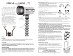
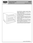
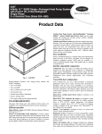
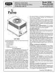
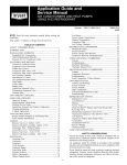
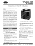
FF1DNA,
FF1DNE
FAN COIL UNITS
Sizes 018, 024, 030
FEATURES
FF1D
The FF1DNA and FF1DNE Fan Coil units are designed as
upflow indoor air handlers for split-system heat pumps and air
conditioners. They are available with factory- or field-installed
electric heaters both of which include the disconnect. A fieldinstalled cooling control with disconnect is also available. A TDR
(Time Delay Relay) is included with either the electric heat or
the cooling control packages. The FF1DNE models are available with a factory installed TXV.
This fan coil may be installed free standing, wall hung or flush
mounted in the wall. The 22-in. wide cabinet size in all models
allows units to fit between standard stud spacings. No return air
ductwork is required if the application provides for return air in
the front of the cabinet through either a louvered closet door or
an optional accessory decorative grille panel.
The cabinet exterior is made of pre-painted galvanized sheet
metal. The cabinet is fully insulated to meet applications in conditioned space. Additional insulation is required if the unit is
installed in an unconditioned space. Unit is supplied with
replaceable filter.
Multispeed direct-drive PSC blower motors have been selected
to provide the proper air handling for both heating and cooling.
Motors are suspended at 3 points on rubber grommets for quieter operation.
All refrigerant lines, electrical power, and thermostat wiring
enter from the top of the cabinet. Sweat-type refrigerant connections on both liquid and suction lines make for swift, low-cost
installation. All service access to the unit is conveniently located
in the front.
The CHECK-FLO-RATER® piston ensures efficient and
dependable refrigerant metering, and eliminates potential service requirements of other metering devices. The CHECK-FLORATER® is located inside the unit, easily accessible for piston
maintenance or changeout.
In addition, units can be factory ordered with a hard shut-off
thermostatic expansion valve (TXV) metering device for performance improvement.
The drain pan is constructed of high-impact, sound-deadening,
corrosion-proof polyester resin. Primary and secondary drain
connections exit from the bottom or either side of the cabinet.
Form No. PDS FF1D.18.2
MODEL NUMBER NOMENCLATURE
F
F
1
D
N
A
018
075
Electric Heater (kw)
000
005
075
011
Nominal Capacity (Btu)
018—18,000
024—24,000
030—30,000
A—Standard
E—TXV
N—208/230-1-60
D—Major Series
1—Upflow
F—Through-the-Wall
UNIT
AR
HE
Y
MP
PU
AT
MANUFACTUR
ER
T
IFIED O ARI A
RT
S
C
CE
YING WITH
PL
OM
AIR
CO
Y
NING
ITIO
ND
UNIT
AR
T
IFIED O ARI A
RT
S
C
CE
YING WITH
PL
OM
MANUFACTUR
ER
F—Fan Coil
®
A
EQ
RI
UIP M E NT
STA
NDARD
0
21
A
EQ
RI
UIP M E NT
STA
NDARD
0
24
• CERTIFICATION • LISTING
• TESTING • INSPECTION
®
CERTIFICATION APPLIES ONLY WHEN THE
COMPLETE SYSTEM IS LISTED WITH ARI.
PHYSICAL DATA
MODEL FF1DNA/FF1DNE
Fan
Rpm (2-Speed)
Motor HP (PSC)
Wheel
Filter (Permanent)
Connections (Sweat)
Suction OD
Liquid OD
Condensate (FPT)
Operating Weight
(With Electric Heat)
018
024
030
(In.)
(In.)
810/750
1/12
10 x 6
16 x 20
980/780
1/5
10 x 6
16 x 20
1110/950
1/3
10 x 6
16 x 20
(In.)
(In.)
(In.)
(Lb)
5/8
3/8
3/4
76
3/4
3/8
3/4
79
3/4
3/8
3/4
82
NOTE: Rough-in dimensions are 38-1/4 x 22-1/4 inches.
CLEARANCES
A minimum clearance of 21 in. is required in front of the access panels for servicing. Please note that this clearance is recommended
for servicing only. Installation clearances from combustible materials are: 0 in. from cabinet and supply-air duct (plenum included).
Leave adequate room for the condensate pan and refrigerant line connection.
NOTE: 22-3/4 to 24-in. on-center between-studs and 38-1/8 to 36-3/4-in. top-to-bottom inside-studs spacing.
—2—
DIMENSIONS — FF1DNA, FF1DNE
LOW VOLTAGE ENTRY
( 7⁄8″ DIA. HOLE)
POWER ENTRY
1 3⁄8″ DIA. KNOCKOUT
7⁄8″ DIA. HOLE
REFRIGERANT
LINES ENTRY
NOTE:
1. SERIES DESIGNATION IS
THE 14TH POSITION
OF UNIT MODEL NUMBER.
1 5⁄8″
15 3⁄16″
2 3⁄4″
8 1⁄4″
TOP VIEW
4 3⁄16″
2 13⁄16″
2 7⁄16″
2 3⁄8″
5 3⁄16″
1 9⁄16″
22 1⁄8″
3⁄4″
7⁄8″
OUTLET AIR
11
3⁄16″
10 1⁄16″
BLOWER, CONTROL AND
ELECTRIC HEATER
ACCESS PANEL
3 1⁄4″
SUCTION
TUBE
COIL
LIQUID TUBE
UNIT CONNECTION SIZES
38 1⁄16″
1 1⁄8″ DIA.
KNOCKOUT
SUCTION, 018, 024, 030 - 3⁄4″ I.D. SWEAT
LIQUID, 3⁄8″ I.D. SWEAT
CONDENSATE, 3⁄4″ NPT
24 1⁄16″
INLET AIR
FILTER MEDIA
3⁄4″
5 11⁄16″
5″
SECONDARY DRAIN
13⁄16″
9 7⁄16″
11 1⁄16″
PRIMARY DRAIN
SIDE VIEW
FRONT VIEW
11 1⁄16″
5″
PATCH PLATE
FAN COIL BASE
BOTTOM VIEW
A98336
—3—
SPECIFICATIONS
UNITS WITHOUT ELECTRIC HEATERS OR CONTROLS
UNIT SIZE
0180
0240
0300
RATINGS & PERFORMANCES
Nominal Capacity (Btuh)*
18,000
24,000
30,000
Nominal Airflow (CFM)
650
870
1080
ELECTRICAL
Unit Volts-Phase (60 Hz)
208/230—1
208/230—1
208/230—1
Operating Voltage Range
187—253
187—253
187—253
Internal Circuit Protection
None
Minimum Ampacity for Wire Sizing
—
Minimum Wire Size†
14
Maximum Fuse Size (Amps or Ckt Bkr)
15
Control Transformer 24V (Va)
—
INDOOR COIL
Rows & Fins Per In.
2 & 14
3 & 14
Height x Width (In.)
18 x 17.8
22 x 17.8
Face Area (Sq Ft)
2.23
2.72
R-22 Refrigerant Metering Device–FF1DNA
Check-Flo-Rater
R-22 Refrigerant Metering Device–FF1DNE
TXV
Piston Number‡
55
63
70
Condensate Drain Connection (Pri-Sec)
3/4 FPT
INDOOR BLOWER & MOTOR
Wheel Diameter x Width (In.)
10 x 6
Filter Size—Cleanable (In.)
16 x 20 x 1
Blower Motor HP
1/12
1/5
1/3
Blower Motor Speeds & Type
2 & PSC
2 & PSC
2 & PSC
Full Load Amps
0.7
1.5
2.0
OPTIONAL EQUIPMENT
Cooling Control Relay-Transformer Package
KFDCC0101DCC
(with TDR)
Louvered Wall Panel with Frame
(6 Pack)
KFBLG0106LGL
Electric Heat Package
See ‘‘Optional Field-Installed Electric Heat Packages’’ Table
UNITS WITH FACTORY-INSTALLED ELECTRIC HEATERS OR CONTROLS
SIZES
018005
018075
018011††
RATINGS & PERFORMANCES
Nominal Capacity (Btuh)*
18,000
18,000
18,000
Nominal Airflow (CFM)
650
650
650
Electric Heating Output (kw @240v)
5.0
7.5
11.0
Electric Heating Capacity (MBH @208/230v)
13.5/16.3
19.9/24.2
28.9/35.1
ELECTRICAL
Unit Volts-Phase (60 Hz)
208/230—1
208/230—1
208/230—1
Operating Voltage Range
187—253
187—253
187—253
Internal Circuit Protection
None
Full Load Amps
18.1/20.0
27.1/30.0
39.8/44.0
Minimum Ampacity for Wire Sizing
23.5/25.9
34.8/38.4
50.6/55.9
Minimum Wire Size†
10/10
8/8
6/6
Maximum Wire Length (Ft)†
112/112
118/118
125/125
Maximum Fuse Size (Amps or Ckt Bkr)
25/30
35/40
60/60
Control Transformer 24V (VA)
40
INDOOR COIL
Rows & Fins Per In.
2 & 14
Height x Width (In.)
18 x 17.8
Face Area (Sq Ft)
2.23
R-22 Refrigerant Metering Device–FF1DNA
Check-Flo-Rater
R-22 Refrigerant Metering Device–FF1DNE
TXV
Piston Number‡
55
Condensate Drain Connection (Pri-Sec)
3/4 FPT
INDOOR BLOWER & MOTOR
Wheel Diameter x Width (In.)
10 x 6
Filter Size—Cleanable (In.)
16 x 20 x 1
Blower Motor HP
1/12
Blower Motor Speeds & Type
2 (PSC)
Full Load Amps
0.7
OPTIONAL EQUIPMENT
Louvered Wall Panel with Frame
(6 Pack)
KFBLG0106LGL
Electric Heat Package
See ‘‘Optional Field-Installed Electric Heat Packages’’ Table
See notes on page 5.
—4—
SPECIFICATIONS Continued
UNITS WITH FACTORY-INSTALLED ELECTRIC HEATERS OR CONTROLS
UNIT SIZE
024005
024075
024011
030005
030075
RATINGS & PERFORMANCES
Nominal Capacity (Btuh)*
24,000
24,000
24,000
30,000
30,000
Nominal Airflow (CFM)
870
1080
Electric Heating Output (kw @240v)
5.0
7.5
11.0
5.0
7.5
Electric Heating Capacity (MBH @208/230v)
14.0/16.9
20.4/24.7
29.4/35.7
14.3/17.2
20.7/25.0
ELECTRICAL
Unit Volts-Phase (60 Hz)
208/230—1
208/230—1
208/230—1
208/230—1
208/230—1
Operating Voltage Range
187—253
187—253
187—253
187—253
187—253
Internal Circuit Protection
None
Full Load Amps
18.1/20.0
27.1/30.0
39.8/44.0
18.1/20.0
27.1/30.0
Minimum Ampacity for Wire Sizing
24.5/26.9
35.8/39.4
51.6/56.9
25.2/27.5
36.4/40.0
Minimum Wire Size†
10/10
8/8
6/6
10/10
8/8
Maximum Wire Length (Ft)†
112/112
117/117
122/122
112/112
117/117
Maximum Fuse Size (Amps or Ckt Bkr)
25/30
40/40
60/60
30/30
40/40
Control Transformer 24V (Va)
40
INDOOR COIL
Rows & Fins Per In.
3 & 14
Height x Width (In.)
18 x 17.8
22 x 17.8
Face Area (Sq Ft)
2.23
2.73
R-22 Refrigerant Metering Device-FF1DNA
Check-Flo-Rater
R-22 Refrigerant Metering Device-FF1DNE
TXV
Piston Number‡
63
70
Condensate Drain Connection (Pri-Sec)
3/4 FPT
INDOOR BLOWER & MOTOR
Wheel Diameter x Width (In.)
10 x 6
Filter Size—Cleanable (In.)
16 x 20 x 1
Blower Motor HP
1/5
1/3
Blower Motor Speeds & Type
2 (PSC)
Full Load Amps
1.5
2.0
OPTIONAL EQUIPMENT (P/N’s)
Louvered Wall Panel with Frame
(6 Pack)
KFBLG0106LGL
Electric Heat Package
See ‘‘Optional Field-Installed Electric Heat Packages’’ Table
030011
30,000
11.0
29.7/36.0
208/230—1
187—253
39.8/44.0
52.3/57.5
6/6
125/125
60/60
* Rated in accordance with U.S. Government DOE test procedures and/or ARI Standard 210/240-94.
† Use copper wire only. Use 75°C in this application. When using non-metallic (NM) sheathed cable, wire size required should be based on that of 60°C conductors, instead of wire sizes shown in table above per NEC 1996 Article 336-30. Length shown is as measured 1 way along wire path between unit and
service panel for voltage drop not to exceed 2%.
‡ Check outdoor unit for required piston size.
†† 018 Size with 11-kw heater not approved for use with heat pumps.
—5—
COOLING CAPACITIES (MBtuh)
COIL REFRIGERANT TEMPERATURE* (°F)
UNIT
SIZE
EVAPORATOR
AIR
CFM and
BF
72
67
62
72
67
400
0.08
500
0.10
600
0.13
650
0.14
600
0.05
700
0.06
875
0.08
750
0.04
900
0.06
1075
0.07
27
13
30
14
33
15
34
16
38
18
41
19
46
21
46
21
50
23
54
25
23
14
25
16
27
17
28
18
32
20
34
21
38
24
38
23
42
26
45
28
19
15
21
17
22
19
23
20
26
21
28
23
31
27
31
25
34
28
37
31
25
12
28
13
30
14
31
14
35
16
38
18
41
20
41
19
46
21
49
23
20
13
22
14
24
16
25
17
29
18
30
19
34
22
33
21
37
23
40
26
018
024
030
35
40
45
Evap Air—Entering Wet-Bulb Temp (°F)
62
72
67
62
72
16
13
18
16
19
18
20
18
22
19
24
21
27
24
26
22
29
25
32
28
* Saturated suction leaving evaporator coil.
Sensible Heat Capacity (1000 Btuh)
22
10
24
12
26
13
27
13
31
15
33
16
37
18
36
17
40
19
43
21
17
11
19
13
21
14
21
15
24
16
26
18
29
20
28
19
31
21
34
23
NOTES:
1. Net capacities shown include a deduction for evaporator fan motor heat.
2. Contact manufacturer for cooling capacities at conditions other than
shown in table.
3. Formulas:
67
62
72
67
62
14
10
15
11
17
13
17
13
19
14
20
15
23
18
22
16
25
18
27
21
10
10
12
12
13
13
14
14
14
14
16
16
19
19
17
17
19
19
22
22
15
8
16
9
18
10
18
10
21
11
22
12
25
14
24
12
26
14
29
16
10
8
11
10
12
11
13
11
13
11
15
13
17
15
16
13
18
15
19
17
8
8
10
10
11
11
12
12
12
12
13
13
16
16
14
14
16
16
18
18
SHC CORRECTION FACTOR
sensible heat cap.
1.09 x CFM
BYPASS
FACTOR
0.10
0.20
0.30
Leaving wb = wb corresponding to enthalpy of air leaving coil (hlwb)
hlwb = hewb —
19
9
21
10
23
11
23
12
26
13
28
14
31
16
30
15
33
17
37
18
55
4. Direct interpolation is permissible. Do not extrapolate.
5. SHC is based on 80°F db temperature of air entering coil. Below 80°F
subtract (corr factor x CFM) from SHC.
Above 80°F db, add (corr factor x CFM) to SHC.
Gross Cooling Capacity (1000 Btuh)
BF—Bypass Factor
Leaving db = entering db —
13
12
15
14
16
16
17
16
18
17
20
19
22
22
21
20
23
22
26
25
50
total capacity (Btuh)
4.5 x CFM
79
81
0.98
0.87
0.76
ENTERING AIR DRY-BULB TEMP (°F)
78
77
76
75
Under 75
82
83
84
85
Over 85
Correction Factor
1.96
2.94
3.92
4.91
Use formula
1.74
2.62
3.49
4.36
shown below
1.53
2.29
3.05
3.82
Interpolation is permissible.
Correction Factor = 1.09 x (1 – BF) x (db – 80)
where hewb = enthalpy of air entering coil.
OPTIONAL FIELD-INSTALLED ELECTRIC HEAT PACKAGES FOR FF1DNA AND FF1DNE
HEATER PART NUMBER
WITH TDR
KFDEH0801D05
KFDEH0901D75
KFDEH1001D11
SIZE
USED
WITH
All
All
All
NOMINAL
KW @
240V
5
7.5
11
HEATER
VOLTS—PHASE
(60 Hz)
208/230—1
208/230—1
208/230—1
* Heater capacities shown here are for the largest size fan coil unit, and they do include blower motor heat.
—6—
HEATER
CAPACITY
(MBH)*
208V
14.3
20.7
29.7
230V
17.2
25.0
36.0
APPROX
SHIP.
WEIGHT
(lbs)
7
7
7
AIR DELIVERY (CFM) AT INDICATED EXTERNAL
STATIC PRESSURE AND VOLTAGE
UNIT
SIZE
BLOWER MOTOR
SPEED
High
Low
High
Low
High
Low
018
024
030
0.1
208V
610
480
895
650
1160
885
0.2
230V
720
580
985
740
1190
1025
208V
580
450
860
620
1105
870
EXTERNAL STATIC PRESSURE—IN. WC
0.3
0.4
230V
208V
230V
208V
230V
665
540
610
475
540
545
415
500
375
430
955
825
915
785
865
710
585
680
550
640
1135
1050
1080
990
1020
985
835
940
810
890
0.5
208V
380
320
730
510
935
770
230V
415
340
805
600
960
840
NOTE: Data reflects a dry coil, filter, and 11-kw electric heater installed.
AIR DELIVERY PERFORMANCE CORRECTION
COMPONENT PRESSURE DROP (IN. WC) AT INDICATED AIRFLOW
AIR DELIVERY (CFM)
1-Element
5 kw
2-Element
7.5 & 11 kw
018
024
030
Electric
Heaters
Dry-toWet
Coil
400
500
600
700
800
900
1000
1100
0.007
0.010
0.015
0.025
0.035
0.055
0.070
0.080
0.010
0.012
0.018
0.028
0.050
0.075
0.100
0.130
—
—
—
0.019
—
—
0.029
0.030
—
0.036
0.039
—
0.043
0.051
0.058
—
0.062
0.070
—
0.076
0.082
—
—
0.091
Subtract the above pressure drop corrections from unit airflow data when that component or condition is used. The remaining external static pressure will be
available for the duct system.
ESTIMATED SOUND POWER LEVEL (dBA)
UNIT
SIZE
FF1-018
FF1-024
FF1-030
CONDITIONS
Ext Static
CFM
Pressure
600
0.25
800
0.25
1000
0.25
OCTAVE BAND CENTER FREQUENCY*
63
64.7
66.0
67.0
125
60.7
62.0
63.0
250
56.7
58.0
59.0
500
53.7
55.0
56.0
1000
51.7
53.0
54.0
2000
49.7
51.0
52.0
* Estimated sound power levels have been derived using the method described in the 1987 ASHRAE HVAC Systems & Applications Handbook,
Chapter 52, p. 52.7.
OTHER ACCESSORIES
KIT NUMBER
DESCRIPTION
USED ON SIZES
KFDCC0101DCC
Cooling Control Package
All
KFBLG0106LGL*
Louvered Wall Panel with Frame
All
* 6 pack
—7—
4000
45.7
47.0
48.0
SERVICE TRAINING
Packaged Service Training programs are an excellent way to increase your
knowledge of the equipment discussed in this manual, including:
• Unit Familiarization
• Maintenance
• Installation Overview • Operating Sequence
A large selection of product, theory, and skills programs is available, using popular
video-based formats and materials. All include video and/or slides, plus companion
book.
Classroom Service Training plus "hands-on" the products in our labs can mean
increased confidence that really pays dividends in faster troubleshooting, fewer
callbacks. Course descriptions and schedules are in our catalog.
CALL FOR FREE CATALOG 1-800-644-5544
[ ] Packaged Service Training [ ] Classroom Service Training
A94328
SPECIFICATIONS SUBJECT TO CHANGE WITHOUT NOTICE
UNIT MUST BE INSTALLED IN ACCORDANCE
WITH INSTALLATION INSTRUCTIONS
Cancels: PDS FF1D.18.1
Form PDS FF1D.18.2
© 2003 Bryant Heating & Cooling Systems, 7310 W. Morris St.
Indpls, IN 46231
—8—
PRINTED IN U.S.A.
Catalog No. 12FF-1D1
1-03