1
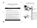
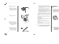
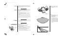
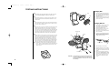
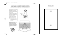
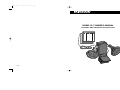
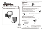
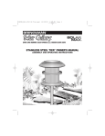
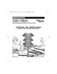
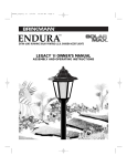
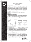
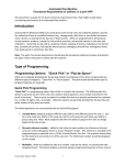
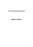
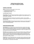
INSTR-SM SL-7.q
4/22/02
11:29 AM
Page 1
R
MODEL SL-7 OWNER’S MANUAL
ASSEMBLY AND OPERATING INSTRUCTIONS
140-6007-0
2/96
INSTR-SM SL-7.q
4/22/02
11:29 AM
Page 2
HOW YOUR HOME SECURITY MOTION
ACTIVATED LIGHTING SYSTEM WORKS
TEMPLATE
The Home Security Motion Activated Lighting
System is designed to turn on automatically at
night when a person enters the detection
zone. The light will stay on as long as the
motion detector senses motion in the zone.
The light will turn off in approximately 90 seconds after the person leaves the detection
zone or stops moving.
During the day, the solar panel converts sunlight into electricity and recharges the battery
in the main housing. At night, the light turns
on automatically when it detects motion using
the electricity stored during that day.
Screw Hole
Solar Panel
NOTE:
cut along dotted line
The number of activations per night are
dependent on your geographical location,
weather conditions and seasonal lighting
availability.
Solar security lights do not receive as
much direct sunlight in winter
months. Therefore, the number of
activations per night will be reduced
during winter.
IMPORTANT: BEFORE FIRST USE
After installing the main housing and solar
panel module, leave the switch in the
“OFF” position and charge in full, direct
sunlight for THREE FULL DAYS. Then
remove the switch label and slide the switch
to the “AUTO” position. The light will turn
on automatically at night when it detects
motion.
Screw Hole
Detection Zone
1
INSTR-SM SL-7.q
4/22/02
11:29 AM
Page 3
ASSEMBLY INSTRUCTIONS
HOME SECURITY ACCESSORIES
Inspect contents of the box to ensure all parts are included and undamaged.
3
For Visa/MasterCard orders, please call 1-800-468-5252, Monday through Friday, 8:30 AM - 5:00 PM Central Standard Time.
100-0057-0
Replacement Bulb
070-6001-0
SL-7 Replacement Battery
112-0010-0
15 ft. Extension Cord
4
A Phillips screwdriver will be required.
1
PARTS LIST:
ONE YEAR LIMITED WARRANTY
Home Security Main Housing
1
For one year from date of purchase, The Brinkmann Corporation warrants the Home Security Motion Activated Lighting System against defects due to workmanship or materials to the original purchaser. The Brinkmann Corporation’s obligations
under this warranty are limited to the following guidelines:
•
This warranty does not extend to the bulb or batteries.
•
This warranty does not cover solar security lights that have been altered or damaged due to: normal wear, abuse,
improper maintenance, improper use, disassembly of parts and/or attempted repair by anyone other than an authorized
employee of The Brinkmann Corporation.
•
This warranty does not cover surface scratches or weathering as this is considered normal wear.
•
Warranty service is limited to repair or replacement or solar security lights which prove defective under normal use and
which upon examination shall indicate to Brinkmann’s satisfaction, they are defective. If Brinkmann confirms the defect
and approves the claim, Brinkmann will elect to repair or replace the solar security light as covered by the terms of this
warranty.
•
2
3
Solar Panel Module with Cord
4
Solar Panel Module Mounting Screws (3)
5
SL-7 Owner’s Manual
Step 1
This warranty extends to the original purchaser only and is not transferable or assignable to subsequent purchasers.
The Brinkmann Corporation requires reasonable proof of purchase. Therefore, we strongly recommend that you retain your
sales receipt or invoice. To obtain repair or replacement of your Home Security Motion Activated Lighting System under the
terms of this warranty, please call Customer Service Department at 1-800-527-0717 for a Return Authorization Number and
further instructions. A receipt will be required. Solar security lights returned to Brinkmann must include your name, address
and telephone number. Please make sure the light is properly packed, postage prepaid, and insured. A Return Authorization
Number must be clearly marked on the outside of the box. Brinkmann cannot be responsible for any solar security lights forwarded to us without a Return Authorization Number.
Main Housing Mounting Screws (2)
2
Template on
back of manual
Select a location and attach the main
housing where you want to detect persons or objects moving at night. Ideal
places are patios, side doors, garages and
pool area. Mount the main housing 6 to 8
feet above ground on a solid surface for
best motion detection and light distribution.
NOTE:
EXCEPT AS ABOVE STATED, THE BRINKMANN CORPORATION MAKES NO OTHER EXPRESS WARRANTY.
THE IMPLIED WARRANTIES OF MERCHANTABILITY AND FITNESS FOR A PARTICULAR PURPOSE ARE LIMITED IN DURATION TO ONE YEAR FROM THE DATE OF PURCHASE. SOME STATES DO NOT ALLOW LIMITATIONS ON HOW LONG AN
IMPLIED WARRANTY LASTS, SO THE ABOVE LIMITATION MAY NOT APPLY TO YOU.
ANY LIABILITY FOR INDIRECT, INCIDENTAL OR CONSEQUENTIAL DAMAGES ARISING FROM THE FAILURE OF THE HOME
SECURITY MOTION ACTIVATED LIGHTING SYSTEM TO COMPLY WITH THIS WARRANTY OR ANY IMPLIED WARRANTY IS
EXCLUDED. CUSTOMER ACKNOWLEDGES THAT THE PURCHASE PRICE CHARGED IS BASED UPON THE LIMITATIONS
CONTAINED IN THE WARRANTY SET OUT ABOVE. SOME STATES DO NOT ALLOW THE EXCLUSION OR LIMITATION OF
INCIDENTAL OR CONSEQUENTIAL DAMAGES, SO THE ABOVE LIMITATION OR EXCLUSION MAY NOT APPLY TO YOU. THIS
WARRANTY GIVES YOU SPECIFIC LEGAL RIGHTS, AND YOU MAY ALSO HAVE OTHER RIGHTS WHICH VARY FROM STATE
TO STATE.
Do not place the main housing in
high traffic areas. Doing so will discharge the battery quickly and unit
will shut down until it is recharged by
the sun. Aim the motion detector
away from streets, busy walk areas,
trees and bushes.
Step 2
To attach the main housing, use the
mounting template in this manual to
install the two main housing mounting
screws. The screw heads must stand out
from the surface by about 5/32". This is
about the thickness of two quarters or
two nickels.
140-6007-0
2/96
2
INSTR-SM SL-7.q
4/22/02
11:29 AM
Page 4
b. If the weather has been cloudy or overcast during the day, the battery will not be charged for operation at night. The light must have
direct sunlight every day to fully charge the battery. If the light does
not receive enough sunlight one day, it will recharge the next sunny
day and resume normal operation.
Step 3
Slide the two slots in the back of main
housing onto the screws.
Troubleshooting &
Important Information (continued)
Step 4
Select a location within 15 feet from the
main housing to mount the solar panel
module. The solar panel module must be
mounted where it will receive full, direct
sunlight for several hours each day.
c. Check the battery on a voltage meter to ensure that battery is
charged to a full voltage of 6-volts. An electronics store will usually
check batteries at no charge. Battery should be replaced periodically
throughout the year, especially after winter months.
d. Diminishing light or gradual decrease in number of activations indicate a dying battery that requires replacement. Replacement battery
may be purchased from The Brinkmann Corporation Customer Service Department by calling 1-800-468-5252.
•
Loose or burned out bulb. Bulbs can become loose over time. Check and
tighten the bulb periodically. If the bulb has burned out, a replacement
can be easily installed. Replacement bulbs may be purchased from The
Brinkmann Corporation Customer Service Department by calling 1-800468-5252.
•
Dirty Solar Panel. A dirty solar panel will not allow the battery to fully
charge. This will shorten battery life. Clean regularly with a dampened
cloth or paper towel.
Step 5
Firmly plug the solar panel module cord
into the main housing.
NOTE: After installing the main housing and
solar panel module, leave the switch
in the “OFF” position and charge in
full, direct sunlight for THREE FULL
DAYS. Then remove the switch label
and slide the switch to the “AUTO”
position. The light will turn on automatically at night when it detects
motion.
If lights come on randomly:
•
•
•
•
Step 6
Mount the solar panel module in a sunny
location where it will receive full, direct
sunlight for several hours each day.
NOTE:
•
Aim motion detector head lower.
Cover areas which may be reflecting signals to motion sensor such as:
cooling or heating ducts, reflective surfaces, metal sheds, smooth walls
or windows, etc..
Rotate the detector head right or left a few degrees.
Mount your motion detector on a firm surface as vibrations can false
trigger the unit.
Aim detector away from busy streets or sidewalks, trees and bushes.
If range is too short or too long:
•
•
Shaded areas will not allow the solar
panel to fully charge the battery. This
will drastically reduce the number of
activations per night.
Position your motion detector so movement is across detection zone.
Aim detector upward to increase range or downward to decrease range.
CAUTION: Do not use any other battery size or type. It will damage the
unit and void the warranty. Do not attempt to open the detector
housing. There are no user serviceable parts inside.
Step 7
Aim the solar panel toward the south, facing upward at about 45° angle. The
adjustable base allows mounting on most
vertical, horizontal or sloping surface
such as a wall, post or roof. Excess cord
can be tucked under the base securely.
3
45°
IMPORTANT: The sealed battery in this
product contains lead and
must be recycled or disposed
of properly. For additional
information regarding disposal, contact your local county
solid waste authority.
8
INSTR-SM SL-7.q
4/22/02
11:29 AM
Page 5
Cleaning
It is important that the solar panel is kept free of dirt and debris. A dirty
solar panel will not allow the battery to fully charge. This will shorten the
life of the battery and cause the light to malfunction. Clean regularly with a
dampened cloth or paper towel.
Storage
Solar security lights can be left outside year round, even in cold weather.
However, if you wish to store your light indoors for more than two or three
days, follow these steps to prevent damage to battery:
Step 8
Point the two floodlights in the desired
direction. You may want to adjust the
floodlights after letting the unit operate
for a few nights.
1. Turn the switch to “OFF” position. Store at room temperature in a
dry area.
2. Never store unit with switch in “AUTO” or “TEST” position. This will
damage the battery and it will not recharge.
3. Store light and solar panel where it can receive some sunlight or
room light each day. The battery needs light to maintain a charge during storage.
Motion Detector Head
Step 9
Position the detector head in the direction
you want to cover. Never
aim the motion detector head directly
at the sun or above a 90° angle (horizontal level). Do not rotate the
head more than 360°.
4. During prolonged storage, unit must be fully charged once every four
months. You may need to replace the battery after prolonged storage.
5. Never store the unit in a box or in a dark room without a source of light
on the solar panel or you may need to replace the battery before next
use.
6. For best performance, do not store for prolonged periods.
Wintertime
Tips
Troubleshooting &
Important Information
1. Clean snow and debris off the solar panel so the battery can recharge.
2. Check and replace battery periodically throughout the year, especially
after winter months.
If lights blink on and off:
•
•
•
Direct lamps away from detector or reposition detector.
Remove heat sources located near or under detector.
Direct detector away from streets or active sidewalks.
If lights do not turn on at night:
Solar Panel
Module Cord
The motion detector covers an area of
130° and a maximum range of approximately 75 feet unless its view is blocked
by a stationary object such as a building
or tree. The higher the motion detector is
mounted, the greater the effective range.
The motion detector is most sensitive to
persons or warm objects moving across
its detection zone, rather than toward or
away from it.
•
•
•
Switch is in the “OFF” Position. When the switch is in the “OFF” position, light will not turn on after dark. Move switch to the “AUTO” position and check for normal operation after dark.
Make sure the solar panel module cord is plugged firmly into main
housing. The battery will not charge if this connection is loose.
90°
Battery is not fully charged or needs replacement:
a. Make sure light is located in an area where the solar panel gets the
maximum amount of full, direct sunlight every day.
75 Feet
7
4
INSTR-SM SL-7.q
4/22/02
11:29 AM
Page 6
TESTING INSTRUCTIONS
Changing Bulb
Step 1
1. Turn lens counterclockwise and remove.
Bulb
After installing your light, leave the switch in the “OFF” position and
charge in full, direct sunlight for THREE FULL SUNNY DAYS.
Lens
Step 2
2. Pull bulb straight out and replace with new
bulb. DO NOT PLACE NEW BULB IN BRASS
GROMMET HOLES.
3. Replace the lens by aligning the slots with the
grooves in the top housing and turning clockwise to lock in place.
After allowing the battery to fully charge, the motion detector can be
adjusted and tested. Point the motion detector head down 15° from
horizontal level.
Step 3
Move the slide switch to “TEST” position. Turn the range knob all the
way to the minimum setting (counterclockwise). The lights will come
on for a few seconds, then turn off.
Changing Batteries
1. Unscrew the four screws in front housing
and separate it from rear housing.
Step 4
2. Carefully peel the tape off the battery,
leaving wires attached to tape.
Wait one minute for the circuit to stabilize, then walk slowly across the
detection zone. The lights will turn on as soon as your presence is
detected. The lights will turn off in approximately 10 seconds after
motion stops or you leave the detection zone. Adjust the detector head
up or down, left or right, in small increments as necessary. Increase
the range by turning the knob clockwise a little at a time and only if
necessary. Most applications work best at the lower range setting.
4. Disconnect wires from battery terminals
and remove battery.
Rear Housing
Battery
Step 5
Place the switch to “AUTO” position. The lights may come on for a few
seconds. This is normal. After dark, test your adjustment by walking
slowly across the detection zone. The lights will turn on when your
presence is detected and will stay on as long there is motion in the
detection zone. The lights will turn off in approximately 90 seconds
after you stop moving or leave the detection zone. If additional adjustments are required, it is recommended that they be made in the test
mode during the following day when the switches are easily visible.
NOTE:
3. Remove the battery from rear housing,
being careful not to pull on wires.
Tape
5. Connect wires to new battery terminals.
Make sure red (+) wire is connected to
red (+) terminal and black (-) wire is connected to black (-) terminal.
Terminal
Wire Connector
Remember to switch to “TEST” for daytime testing and switch
back to “AUTO” for nighttime operation. The motion detector has a
built-in photocell sensor that prevents daytime operation in the
“AUTO” position.
6. Place new battery in rear housing.
7. Attach tape and wires to front of battery.
8. Attach the front housing to rear housing
using the four screws that were removed
in Step 1.
Front Housing
IMPORTANT: The sealed battery in this product contains lead and must
be recycled or disposed of properly. For additional information regarding disposal, contact your local county solid
waste authority.
5
9. Place switch in the “OFF” position and
charge in full, direct sunlight for THREE
FULL DAYS. Then slide the switch to the
“AUTO” position. The light will turn on
automatically at night when it detects
motion.
6
INSTR-SM SL-7.q
4/22/02
11:29 AM
Page 5
Cleaning
It is important that the solar panel is kept free of dirt and debris. A dirty
solar panel will not allow the battery to fully charge. This will shorten the
life of the battery and cause the light to malfunction. Clean regularly with a
dampened cloth or paper towel.
Storage
Solar security lights can be left outside year round, even in cold weather.
However, if you wish to store your light indoors for more than two or three
days, follow these steps to prevent damage to battery:
Step 8
Point the two floodlights in the desired
direction. You may want to adjust the
floodlights after letting the unit operate
for a few nights.
1. Turn the switch to “OFF” position. Store at room temperature in a
dry area.
2. Never store unit with switch in “AUTO” or “TEST” position. This will
damage the battery and it will not recharge.
3. Store light and solar panel where it can receive some sunlight or
room light each day. The battery needs light to maintain a charge during storage.
Motion Detector Head
Step 9
Position the detector head in the direction
you want to cover. Never
aim the motion detector head directly
at the sun or above a 90° angle (horizontal level). Do not rotate the
head more than 360°.
4. During prolonged storage, unit must be fully charged once every four
months. You may need to replace the battery after prolonged storage.
5. Never store the unit in a box or in a dark room without a source of light
on the solar panel or you may need to replace the battery before next
use.
6. For best performance, do not store for prolonged periods.
Wintertime
Tips
Troubleshooting &
Important Information
1. Clean snow and debris off the solar panel so the battery can recharge.
2. Check and replace battery periodically throughout the year, especially
after winter months.
If lights blink on and off:
•
•
•
Direct lamps away from detector or reposition detector.
Remove heat sources located near or under detector.
Direct detector away from streets or active sidewalks.
If lights do not turn on at night:
Solar Panel
Module Cord
The motion detector covers an area of
130° and a maximum range of approximately 75 feet unless its view is blocked
by a stationary object such as a building
or tree. The higher the motion detector is
mounted, the greater the effective range.
The motion detector is most sensitive to
persons or warm objects moving across
its detection zone, rather than toward or
away from it.
•
•
•
Switch is in the “OFF” Position. When the switch is in the “OFF” position, light will not turn on after dark. Move switch to the “AUTO” position and check for normal operation after dark.
Make sure the solar panel module cord is plugged firmly into main
housing. The battery will not charge if this connection is loose.
90°
Battery is not fully charged or needs replacement:
a. Make sure light is located in an area where the solar panel gets the
maximum amount of full, direct sunlight every day.
75 Feet
7
4
INSTR-SM SL-7.q
4/22/02
11:29 AM
Page 4
b. If the weather has been cloudy or overcast during the day, the battery will not be charged for operation at night. The light must have
direct sunlight every day to fully charge the battery. If the light does
not receive enough sunlight one day, it will recharge the next sunny
day and resume normal operation.
Step 3
Slide the two slots in the back of main
housing onto the screws.
Troubleshooting &
Important Information (continued)
Step 4
Select a location within 15 feet from the
main housing to mount the solar panel
module. The solar panel module must be
mounted where it will receive full, direct
sunlight for several hours each day.
c. Check the battery on a voltage meter to ensure that battery is
charged to a full voltage of 6-volts. An electronics store will usually
check batteries at no charge. Battery should be replaced periodically
throughout the year, especially after winter months.
d. Diminishing light or gradual decrease in number of activations indicate a dying battery that requires replacement. Replacement battery
may be purchased from The Brinkmann Corporation Customer Service Department by calling 1-800-468-5252.
•
Loose or burned out bulb. Bulbs can become loose over time. Check and
tighten the bulb periodically. If the bulb has burned out, a replacement
can be easily installed. Replacement bulbs may be purchased from The
Brinkmann Corporation Customer Service Department by calling 1-800468-5252.
•
Dirty Solar Panel. A dirty solar panel will not allow the battery to fully
charge. This will shorten battery life. Clean regularly with a dampened
cloth or paper towel.
Step 5
Firmly plug the solar panel module cord
into the main housing.
NOTE: After installing the main housing and
solar panel module, leave the switch
in the “OFF” position and charge in
full, direct sunlight for THREE FULL
DAYS. Then remove the switch label
and slide the switch to the “AUTO”
position. The light will turn on automatically at night when it detects
motion.
If lights come on randomly:
•
•
•
•
Step 6
Mount the solar panel module in a sunny
location where it will receive full, direct
sunlight for several hours each day.
NOTE:
•
Aim motion detector head lower.
Cover areas which may be reflecting signals to motion sensor such as:
cooling or heating ducts, reflective surfaces, metal sheds, smooth walls
or windows, etc..
Rotate the detector head right or left a few degrees.
Mount your motion detector on a firm surface as vibrations can false
trigger the unit.
Aim detector away from busy streets or sidewalks, trees and bushes.
If range is too short or too long:
•
•
Shaded areas will not allow the solar
panel to fully charge the battery. This
will drastically reduce the number of
activations per night.
Position your motion detector so movement is across detection zone.
Aim detector upward to increase range or downward to decrease range.
CAUTION: Do not use any other battery size or type. It will damage the
unit and void the warranty. Do not attempt to open the detector
housing. There are no user serviceable parts inside.
Step 7
Aim the solar panel toward the south, facing upward at about 45° angle. The
adjustable base allows mounting on most
vertical, horizontal or sloping surface
such as a wall, post or roof. Excess cord
can be tucked under the base securely.
3
45°
IMPORTANT: The sealed battery in this
product contains lead and
must be recycled or disposed
of properly. For additional
information regarding disposal, contact your local county
solid waste authority.
8
INSTR-SM SL-7.q
4/22/02
11:29 AM
Page 2
HOW YOUR HOME SECURITY MOTION
ACTIVATED LIGHTING SYSTEM WORKS
TEMPLATE
The Home Security Motion Activated Lighting
System is designed to turn on automatically at
night when a person enters the detection
zone. The light will stay on as long as the
motion detector senses motion in the zone.
The light will turn off in approximately 90 seconds after the person leaves the detection
zone or stops moving.
During the day, the solar panel converts sunlight into electricity and recharges the battery
in the main housing. At night, the light turns
on automatically when it detects motion using
the electricity stored during that day.
Screw Hole
Solar Panel
NOTE:
cut along dotted line
The number of activations per night are
dependent on your geographical location,
weather conditions and seasonal lighting
availability.
Solar security lights do not receive as
much direct sunlight in winter
months. Therefore, the number of
activations per night will be reduced
during winter.
IMPORTANT: BEFORE FIRST USE
After installing the main housing and solar
panel module, leave the switch in the
“OFF” position and charge in full, direct
sunlight for THREE FULL DAYS. Then
remove the switch label and slide the switch
to the “AUTO” position. The light will turn
on automatically at night when it detects
motion.
Screw Hole
Detection Zone
1
INSTR-SM SL-7.q
4/22/02
11:29 AM
Page 1
R
MODEL SL-7 OWNER’S MANUAL
ASSEMBLY AND OPERATING INSTRUCTIONS
140-6007-0
2/96
INSTR-SM SL-7.q
4/22/02
11:29 AM
Page 3
ASSEMBLY INSTRUCTIONS
HOME SECURITY ACCESSORIES
Inspect contents of the box to ensure all parts are included and undamaged.
3
For Visa/MasterCard orders, please call 1-800-468-5252, Monday through Friday, 8:30 AM - 5:00 PM Central Standard Time.
100-0057-0
Replacement Bulb
070-6001-0
SL-7 Replacement Battery
112-0010-0
15 ft. Extension Cord
4
A Phillips screwdriver will be required.
1
PARTS LIST:
ONE YEAR LIMITED WARRANTY
Home Security Main Housing
1
For one year from date of purchase, The Brinkmann Corporation warrants the Home Security Motion Activated Lighting System against defects due to workmanship or materials to the original purchaser. The Brinkmann Corporation’s obligations
under this warranty are limited to the following guidelines:
•
This warranty does not extend to the bulb or batteries.
•
This warranty does not cover solar security lights that have been altered or damaged due to: normal wear, abuse,
improper maintenance, improper use, disassembly of parts and/or attempted repair by anyone other than an authorized
employee of The Brinkmann Corporation.
•
This warranty does not cover surface scratches or weathering as this is considered normal wear.
•
Warranty service is limited to repair or replacement or solar security lights which prove defective under normal use and
which upon examination shall indicate to Brinkmann’s satisfaction, they are defective. If Brinkmann confirms the defect
and approves the claim, Brinkmann will elect to repair or replace the solar security light as covered by the terms of this
warranty.
•
2
3
Solar Panel Module with Cord
4
Solar Panel Module Mounting Screws (3)
5
SL-7 Owner’s Manual
Step 1
This warranty extends to the original purchaser only and is not transferable or assignable to subsequent purchasers.
The Brinkmann Corporation requires reasonable proof of purchase. Therefore, we strongly recommend that you retain your
sales receipt or invoice. To obtain repair or replacement of your Home Security Motion Activated Lighting System under the
terms of this warranty, please call Customer Service Department at 1-800-527-0717 for a Return Authorization Number and
further instructions. A receipt will be required. Solar security lights returned to Brinkmann must include your name, address
and telephone number. Please make sure the light is properly packed, postage prepaid, and insured. A Return Authorization
Number must be clearly marked on the outside of the box. Brinkmann cannot be responsible for any solar security lights forwarded to us without a Return Authorization Number.
Main Housing Mounting Screws (2)
2
Template on
back of manual
Select a location and attach the main
housing where you want to detect persons or objects moving at night. Ideal
places are patios, side doors, garages and
pool area. Mount the main housing 6 to 8
feet above ground on a solid surface for
best motion detection and light distribution.
NOTE:
EXCEPT AS ABOVE STATED, THE BRINKMANN CORPORATION MAKES NO OTHER EXPRESS WARRANTY.
THE IMPLIED WARRANTIES OF MERCHANTABILITY AND FITNESS FOR A PARTICULAR PURPOSE ARE LIMITED IN DURATION TO ONE YEAR FROM THE DATE OF PURCHASE. SOME STATES DO NOT ALLOW LIMITATIONS ON HOW LONG AN
IMPLIED WARRANTY LASTS, SO THE ABOVE LIMITATION MAY NOT APPLY TO YOU.
ANY LIABILITY FOR INDIRECT, INCIDENTAL OR CONSEQUENTIAL DAMAGES ARISING FROM THE FAILURE OF THE HOME
SECURITY MOTION ACTIVATED LIGHTING SYSTEM TO COMPLY WITH THIS WARRANTY OR ANY IMPLIED WARRANTY IS
EXCLUDED. CUSTOMER ACKNOWLEDGES THAT THE PURCHASE PRICE CHARGED IS BASED UPON THE LIMITATIONS
CONTAINED IN THE WARRANTY SET OUT ABOVE. SOME STATES DO NOT ALLOW THE EXCLUSION OR LIMITATION OF
INCIDENTAL OR CONSEQUENTIAL DAMAGES, SO THE ABOVE LIMITATION OR EXCLUSION MAY NOT APPLY TO YOU. THIS
WARRANTY GIVES YOU SPECIFIC LEGAL RIGHTS, AND YOU MAY ALSO HAVE OTHER RIGHTS WHICH VARY FROM STATE
TO STATE.
Do not place the main housing in
high traffic areas. Doing so will discharge the battery quickly and unit
will shut down until it is recharged by
the sun. Aim the motion detector
away from streets, busy walk areas,
trees and bushes.
Step 2
To attach the main housing, use the
mounting template in this manual to
install the two main housing mounting
screws. The screw heads must stand out
from the surface by about 5/32". This is
about the thickness of two quarters or
two nickels.
140-6007-0
2/96
2