1
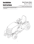
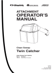
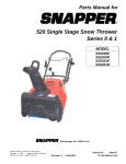
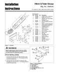
Lift Lever Kit
Installation
Instructions
Mfg. No. 1694561
For Baron / 2400 / RD Series
3
2
6
10
1
4
12
13
9
11
14
7
5
8
15
21
22
13
15
18
19
17
16
15
20
21
23
Kit Contents:
Ref
1
2
3
4
5
6
7
8
9
10
11
12
Part No. Qty.
1725959A 1
1960033
1
1723124
1
1713995
1
1960674
1
1723321
1
1725958
1
1721999A 1
1960126
1
1727441A 1
1927609
1
1931277
2
Description
ROD & TUBE ASSEMBLY
CLIP, Hair Pin
BUTTON, Red
GRIP, Soft, Black
PUSH NUT, 1/4
SPRING, Compression
ROD, Latch
LATCH, Lift Lever
PUSH NUT, 1/4
LEVER ASSEMBLY
PIN, 3/8 x 1
NUT, Hex, Flange Whiz Lock, 5/16-18
Figure 1. Contents
13
14
15
16
17
18
19
20
21
22
23
1708298
1732511A
1960074
1960585
1725957
1732510A
2157081
1733693
1919381
1723683
1724638
2
1
4
2
2
1
1
1
2
2
1
PIN, Round Head, Drilled, 3/8 x 1
BRACKET, Mounting
CLIP, Hair Pin
CAPSCREW, Hex,5/16-18 x 1-3/4
PAD, Rubber
SUPPORT PLATE
SPACER
LIFT SHAFT ASSEMBLY
WASHER, .34 x 1 x .13
PIN, CLEVIS
GUARD ASSY, DEFLECTOR
LIFT LEVER KIT FITS ON BARON / 2400 / RD
Product
Serial Number Range
Number
Requires p/n 1726404
1694328
All
1694329
All
1694346
All
1694347
All
1694384
All
1694315
00001-00999
1694481
00001-00999
1694482
00001-00999
1694483
00001-00999
1694484
00001-00999
1694485
00001-00999
1694504
00001-00999
This kit adds a lift lever for front mounted
attachments.
WARNING
Before beginning any service work turn off the
PTO, set the parking brake, turn off the ignition,
and disconnect the spark plug wire(s).
1
Installation Instructions
Lift Lever Kit
A
C
D
B
Figure 4. Lift Lever Assembly 1726404
Figure 2. Capscrew Removal
A. Nuts, 5/16-18
C. Right Rear Seat Deck
B. Capscrews, 5/16-18 x 3/4 D. Frame
B
C
A
C
C
D
E
D
E
F
B
A
Figure 5. Remove Old Lift Shaft Assembly
A. Lift Shaft Assembly
D. Nut, KEPS, 5/16-18
B. Lift Rod
E. Washer
C. Carriage Bolts,
F. Hair Pin
5/16-18 x 3/4
Figure 3. Bracket installation
A. Nuts, 5/16-18 (Existing) C. RIght Rear Seat Deck
B. Capscrews,
D. Frame
5/16-18 x 1-3/4 (New)
E. Bracket
INSTALLATION
ALL MODELS
1. Remove mower deck as described in the Operator’s
Manual.
C
B
2. Remove 5/16-18 nuts (A, Figure 2) and 5/16-18 x 3/4
capscrews (B) which hold the right rear seat deck (C)
to the frame(D). Discard capscrews and nuts.
3. Install bracket (E, Figure 3) using new 5/16-18 x 13/4 capscrews (B) and new 5/16-18 locknuts (A).
C
Install New Lift Shaft Assembly
MODELS WITH SERIAL NUMBERS BELOW (<) 00999
D
1. Remove hair pin (F, Figure 5) and washer (E).
E
2. Remove lift rod (B) from lift shaft assembly (A).
F
3. Remove and discard lift shaft assembly (A). Retain
hardware.
Figure 6. Install New Lift Shaft Assembly
A. Lift Shaft Assembly
D. Nut, KEPS, 5/16-18
B. Lift Rod
E. Washer
C. Carriage Bolts,
F. Hair Pin
5/16-18 x 3/4
4. Mount the new lift shaft assembly (A, Figure 6) to the
frame using four 5/16-18 x 3/4 carriage bolts (C) and
5/16-18 KEPS nuts (D).
5. Connect the lift rod (B) to the lift shaft assembly (A)
using washer (E) and hair pin (F).
A
2
Installation Instructions
Lift Lever Kit
Install New Lift Shaft Assembly
BARON 2007 AND NEWER MODELS
1. Slide Lift Shaft Assy (A, Figure 7) into key-slotted
hole (existing - attached to frame (B)) aligning key in
Lift Shaft Assy (A) with key slot in hole (B).
C
2 Rotate the Lift Shaft Assy (C) 180 degree to the right
to secure the Lift Shaft Assy in place.
B
A
Figure 7. Install Lift lever Assembly
A. Lift Lever Assembly
B. Existing hole
C. Rotate Lift Lever Assembly 180 Degrees
ALL MODELS
A
Install Front Attachment Lift Lever & Rod
B
1. Slide the lift lever assembly (A, Figure 8) on to the
end of the shaft assembly and on to the edge of the
tractor.
B
D
2. Secure to mounting bracket (D, Figure 8) using clevis
pins (B), spacer (E), and hair pins (C).
C
3. Slide lift rod (A, Figure 9) into the bottom hole in the
lift lever assembly (B). Secure with hair pin (C).
Install front attachment & hitch as outlined in
Operator’s Manual or Installation Instructions.
E
Edge of
Tractor
End of
Shaft
Assembly
Figure 8. Install Lift lever Assembly
A. Lift Lever Assembly
B. Clevis Pin
C. Hair Pin
D. Mounting Bracket
E. Spacer
3
Installation Instructions
Lift Lever Kit
Install Support Assembly
1. Hang support plate (A, Figure 10) onto shaft assembly (B).
B
2. The post on the support plate (A) fits between the
clamp support (C) and hitch assembly (D). See SubFrame Hitch Installation Instructions for details on
installing sub frame.
C
A
Figure 9. Install Lift Rod
A. Lift Rod
B. Lift Lever Assembly
C. Hair Pin
Install Mower Deck
1. Remove Lift Lever Assembly (A, Figure 8).
2. Install mower deck as described in Operator’s
Manual or Dealer Setup Instructions.
B
A
C
Figure 10. Install Support Plate
A. Support Plate
C. Clamp Support
B. Shaft Assembly
D. Hitch Assembly
Install Deflector Guard
B
1. Install Deflector Guard Assy (A, Figure 11) using
Clevis Pins (B), Washers (C), and Hair Pins (D) as
shown.
D
C
A
Figure 11. Install Support Plate
A. Deflector Guard Assy
C. Washer
B. Clevis Pin
D. Hair Pin
Form No. 1726469-01
Rev. 11/2006
Briggs & Stratton Yard Power Products Group
Copyright © 2006 Briggs & Stratton Corporation
Milwaukee, WI USA. All Rights Reserved
MANUFACTURING, INC.
500 N Spring Street / PO Box 997
Port Washington, WI 53074-0997 USA
TP 200-4020-01-AT-SMN
4