1
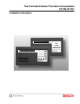
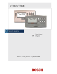
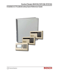
D1255/D1255B
Installation Instructions
EN
Keypads
D1255/D1255B | Installation Instructions | 1.0 Description
Configurations combining supervised and unsupervised
keypads are also possible.
1.0 Description
The D1255/D1255B Keypad is an SDI Bus compatible
device used with Bosch Security Systems control
panels. The D1255/D1255B features a keypad that
illuminates when you press the keys, a 16-character
English language display, and a built-in speaker that
emits several distinct warning tones.
The D1255/D1255B Keypad is a low profile, surfacemounted unit.
The control panel supplies all power and data
requirements for the D1255/D1255B using a simple
four-wire connection. For specific control panel
compatibility refer to Table 6 on page 6.
Refer to the Current Rating Chart for Standby Battery
Calculations provided in the following documentation,
based on which control panel connected to the
D1255/D1255B Keypad to determine if you need an
additional power supply:
• D9412G/D7412G Approved Applications Compliance
Guide (P/N: 43494) if using a D9412G or D7412G
Control Panel.
• D7212G Approved Applications Compliance Guide
(P/N: 4998138560) if using a D7212G Control
Panel.
You can program the control panel to generate
messages to the Central Station identifying the
supervised keypad that is in trouble. If a keypad loses
communication with the control panel for more than
60 sec, the keypad buzzes and CALL FOR SERVICE
displays. The control panel transmits a serial device
trouble report to the receiver. The keypad shows SDI
FAILURE # if the Modem IIIa2 communication format
is used or TROUBLE ZN D if the BFSK communication
format is used. For more information, refer to the
D6600 Computer Interface Manual (P/N: 4998122703).
Depending on programming in the control panel, the
D1255/D1255B permits remote control of relays and
real time clock display; adding, deleting and changing
passcodes; system tests, and more. Refer to the Keypad
and User Interface sections of the D9412G/D7412G
Program Entry Guide (P/N: 47775) for complete
programming details on keypad options. You can
initiate a variety of system commands with the touch of
two or three keys at the D1255/D1255B keypad. To
navigate through the system use the four keys near the
bottom of the keypad (Item 3 in Figure 1).
Figure 1: D1255/D1255B Layout
1
Ai AREA i IS OFF
ALL
INSTANT
1
2
DELAY
3
RESET
WATCH
4
5
6
SPECIAL
PARTIAL
POLICE
7
8
9
5
BYPASS
0
2
COMMAND
MENU
ESC
4
YES
PREV
NEXT
ENT
3
D1255
D1255B
1
5
4
3
2
4998152977A
1 - Alphanumeric display
2 - Siren/Speaker
2
3- Function Keys
4 - Command Bar
5 - Digital Keypad
Bosch Security Systems | 8/04 | 74-06819-000-F
D1255/D1255B | Installation Instructions | 2.0 Digital Keypad
2.0 Digital Keypad
The D1255/D1255B Keypad features a digital keypad
for accessing the menus, entering user passcodes and
executing system commands in the control panel. As
you press keys, the D1255/D1255B emits a muted
beep tone (refer to Section 2.3 Audible Tones) to indicate
that the entry is accepted. The keypad lights when you
press keys, and remains lit for 20 sec.
When entering a passcode, press keys within 15 sec of
each other. If 15 sec elapse between keystrokes, the
entire entry clears, and you must start over. The
keypad also "times out" on other functions if you wait
15 sec or more between key presses.
2.1
Keypad Function Keys
The D1255/D1255B has five function keys. These keys
control your system.
Table 1: Function Keys
Key
COMMAND
ENT/YES
PREV
NEXT
MENU/ESC
2.2
Description
Use the [COMMAND] bar in combination
with one or two numeric keys to perform a
function.
Use the [ENT/YES] key to complete the
entry of your passcode at the keypad.
The [ENT/YES] key also selects the menu
item shown during a menu selection.
When viewing a list, pressing the [PREV]
key returns you to the previously shown
item.
Press the [NEXT] key to pass over the
present item in a menu or list.
Use the [ESC/MENU] key to returns to
the idle display.
Display
The D1255/D1255B Keypad displays the latest status
conditions of the security system using words, numbers,
and symbols in its display. When a series of events
occur that affects the system, the D1255/D1255B
displays each event in order of its priority.
For a complete listing and description of the
D1255/D1255B 16-character displays and command
functions available, consult the following
documentation:
Bosch Security Systems | 8/04 | 74-06819-000-F
For the D9412G, D7412G, D7212G, D9124, D9412,
D9112, D7412, and D7212 Control Panels consult
Security System User’s Guide (P/N: 71-06141-000) and the
D9412G/D7412G Program Entry Guide (P/N: 47775).
2.3
Audible Tones
The D1255/D1255B Keypad has a built-in speaker that
produces several distinct warning tones. The speaker
volume is changed by adjusting the potentiometer
(refer to Item 5 in Figure 2 on page 4). Turn the
potentiometer clockwise to increase volume and
counterclockwise to decrease volume. The speaker
volume also changes as you adjust the brightness of the
display. Refer to Command 49 “Dim Display” in the
Security System User’s Guide (P/N: 71-06141-000) for
more information. You cannot connect external
annunciation devices to the D1255/D1255B. The tones
in Table 2 are silenced by entering a programmed
passcode with the appropriate authority.
Table 2: Audible Tones
Tone
Burglary
Signal
Entrance
Warning
Exit
Warning
Fire Signal
Invalid Key
Buzz
Keypad
Encoding
Tone
Trouble
Buzzer
Watch
Tone
Description
When an area is in alarm, the D1255/D1255B
emits a steady, high-pitched “bell” tone.
The D1255/D1255B emits an intermittent beep
tone during entry delay periods to remind the
user to disarm the area. This is a programmable
option.
The D1255/D1255B emits an intermittent beep
tone during exit delay and counts down the
number of seconds left until arming takes place.
This is a programmable option.
When an area is in fire alarm, the
D1255/D1255B emits a pulsed, high-pitched
“bell” tone.
Pressing an invalid key, or sequence of keys,
causes the D1255/D1255B to emit a flat buzz
tone.
The D1255/D1255B emits a muted beep tone
as each key is pressed to indicate that the entry
is accepted. To disable this feature refer to
Section 3.3.1 Setting the DIP Switches on
page 5.
When a trouble event occurs, such as a service
alert, the D1255/D1255B emits a two tone
warble until you enter COMMAND 4.
When you activate the Watch feature, an
intermittent beep tone (the same as the
Entrance Warning Signal) alerts the user
anytime a watch point is faulted. This option is
programmable by point.
3
D1255/D1255B | Installation Instructions | 3.0 Installation
Figure 2: D1255/D1255B Internal Features
1
2
3
2
4
9
1
2
3
4
5
5
6
3
3
12345-
6
8
16-Character Display
Top Tab Slot
Mounting Hole
Keypad
Speaker Volume Control (Potentiometer)
3.0 Installation
3.1
Mounting the D1255/D1255B
The D1255/D1255B Keypad can be mounted using the
following optional packages:
• D54B Keypad Flush Mount Kit (Brass)
• D54C Keypad Flush Mount Kit (Stainless)
• D55 Keypad Desk Stand - Desktop
• D56 and D56R Keypad Conduit Box
3.1.1
Mounting Locations
Do not mount the keypad in a location
where it is exposed to direct sunlight.
Direct sunlight can interfere with the
D1255/D1255B display screen visibility
and damage internal components.
Do not mount the D1255/D1255B in wet
or moist locations.
3.2
Wiring
Data and power connections between the control panel
and the D1255/D1255B require a four-wire flying lead.
The D1255/D1255B includes a wiring assembly
consisting of four color-coded flying leads and a female
four-pin connector plug at one end.
The maximum recommended wire run for each
D1255/D1255B is 2000 ft (610 m) with either 22 AWG
(0.8 mm) gauge or 18 AWG (1.2 mm) gauge wire.
4
7
6789-
6
Bottom Tab Slot
Dip Switch
Four-Wire Flying Lead Connector
Speaker
To wire the D1255/D1255B:
1. Power down the control panel.
2. Gently push in the two bottom tabs of the
D1255/D1255B enclosure cover using a small flatbladed screwdriver.
3. Lift the D1255/D1255B cover away from the base
as the tabs are pushed back.
4. Set the address switches (refer to Section 3.3.1
Setting the DIP Switches on page 5).
5. Connect the flying leads of the wiring assembly
(provided) to the wires from the control panel
(Table 3).
6. Turn the keypad over and plug in the wiring
connector through the opening in the back of the
enclosure base.
7. Mount the keypad base in the desired location.
8. Secure the keypad in place from inside the
enclosure base by inserting screws in the mounting
holes.
9. Replace the cover by aligning and inserting the top
two tabs of the enclosure cover into the top two tab
slots of the enclosure base.
10. Hold the top edges of the enclosure cover and base
in position.
11. Push the tabs inward.
12. Press the enclosure and cover together until the
cover snaps into place.
Bosch Security Systems | 8/04 | 74-06819-000-F
D1255/D1255B | Installation Instructions |
13. Press each key on the keypad toward the top of the
keypad to ensure proper alignment and operation
of each key through the mating keypad faceplate
openings.
3.3.1
Setting the DIP Switches
Switches 1 through 3 assign the address for the specific
keypad. Leave Switches 4 and 6 in the ON position.
For supervised keypads, assign only one
keypad to each address. Switch 5 toggles
the encoding tone ON and OFF. With the
encoding tone turned ON, the keypad
sounds a beep every time a key is
pressed.
Table 3: Wiring Connections
Four-Wire Flying Leads
from control panel
DATA BUS B (30)
DATA BUS A (31)
POWER + (32*)
COMMON – (29*)
D1255/D1255B Flying
Leads
To Data Out (Green)
To Data In (Yellow)
To 12 VDC (Red)
To Common (Black)
Table 4: Switch Settings
* = only on the D9412G Control Panel
Switch
Address #
3.3
DIP Switch Settings and Associated
Functions
Select the address of each keypad and silence the
keypad encoding tone by setting the six-position DIP
Switch (refer to Item 7 in Figure 2) located under the
D1255/D1255B Keypad cover.
1
2
3
4
5
6
7
8
1
ON
OFF
ON
OFF
ON
OFF
ON
OFF
2
ON
ON
OFF
OFF
ON
ON
OFF
OFF
3
ON
ON
ON
ON
OFF
OFF
OFF
OFF
4
ON
ON
ON
ON
ON
ON
ON
ON
5*
6
ON
ON
ON
ON
ON
ON
ON
ON
*Encoding Tone ON/OFF.
4.0 Specifications
Table 5: D1255/D1255B Specifications
Power
Current Required
Wiring
Dimensions
HxWxD
Color
Display
Operating Temperature
Relative Humidity
Nominal 12 VDC supplied by the control panel
Idle:
104 mA, armed or disarmed.
Maximum:
206 mA, with keypad lighted and warning tone ON.
Four-wire expansion cable supplies Data In, Data Out, +12 VDC, and Common.
Maximum resistance on the conductors connected to SDI BUS A and SDI BUS B is 25 Ω.
4.6 in. x 8.1 in. x 0.8 in.
(11.6 cm x 20.7 cm x 20.7 cm)
D1255
PMS Warm Gray
D1255B
White and PMS 429 Gray
16-character vacuum fluorescent display. Each character is a 14-segment unit. Soft blue color.
+32°F to +122°F (0°C to +50°C)
5% to 85% @ +86°F (+30°C)
Bosch Security Systems | 8/04 | 74-06819-000-F
5
D1255/D1255B | Installation Instructions | 4.0 Specifications
Table 6: Control panel compatibility chart
Control panel
D9412G
D7412G
D7212G
D9124
D9412
D9112
D7412
D7212
6
Maximum Number of Keypads
Supervised
8
8
8
8
8
8
8
8
Unsupervised
32
32
32
32
32
32
32
32
Bosch Security Systems | 8/04 | 74-06819-000-F
D1255/D1255B | Installation Instructions | Notes
Bosch Security Systems | 8/04 | 74-06819-000-F
7
Bosch Security Systems
130 Perinton Parkway
Fairport, NY 14450-9199
Customer Service: (800) 289-0096
Technical Support: (888) 886-6189
© 2004 Bosch Security Systems
74-06819-000-F