1
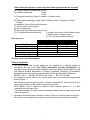
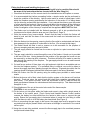
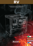
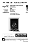
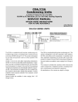
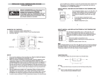
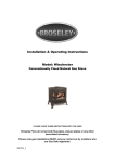
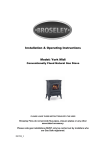
THE
PUREGLOW MULTIFLUE
RADIANT GAS FIRE
MODEL NUMBERS:
EAR16NG & EAR16P
Manual & Remote Control Models
INSTALLATION, USER AND SERVICING INSTRUCTIONS
THESE INSTRUCTIONS MUST REMAIN WITH THE USER
0120
THIS APPLIANCE MEETS THE REQUIREMENTS OF THE EUROPEAN GAS DIRECTIVE
June 2005
(C)EAR16
Issue 5
Contents
Page No.
List of components
3
Appliance Data
3
GENERAL INSTALLATION REQUIREMENTS
3
Fitting the Appliance
3
Fitting the firebox and installing the burner unit
5
Additional notes for handset remote models
6
Fitting the optional spacer frame
6
Laying of ceramics & coals
6
Laying of ceramics, coals & pebbles
7
8
COMMISSIONING
Lighting the appliance
8
Check for spillage
8
Briefing the User
8
9
USERS GUIDE
Useful tips & recommendations
9
Operation of your fire
9
Manual Appliances
10
Handset remote models
10
Cleaning your fire
13
Assembling the fire and laying the coals
13
13
SERVICING & MAINTENANCE
Spares Parts list
14
Installation & Service Record
15
Guarantee
16
Important Notes – Please read before undertaking the installation
1. This is not a “Do it yourself” product and it must be installed by a
competent person.
2. The chimney must be swept before the appliance is fitted.
3. The Installation Instructions must be adhered to without exception.
2
Before fitting this appliance, ensure that the following components are enclosed
(a) Pureglow Radiant (complete with burner)
(b) Ceramic components.
1 Base
1 Rear
(c) Coal pack comprising; 5 large, 5 medium, 23 random coals,
or
(d) Pebble pack comprising 5 Large Coals, 5 Medium Coals, 12 Large and 3 Small
Pebbles.
(e) Installation, User & Servicing Instructions
(f) Trim (to order) and 4 magnets
(g) Roll of sealing tape
(h) Wire fixing kit c/w with instructions for use.
(i) For Handset Remote Models only
1 Handset Control unit c/w 9V alkaline battery
1 Signal Receiver / Battery Holder
4 x 1.5 volt AA size alkaline batteries
APPLIANCE DATA
EAR16NG
Gas Type
Supply Pressure (mb)
Heat Input (Gross) (kW)
Injector Size (mm)
Gas Connection
Weight (kg)
EAR16P
Natural Gas
Propane
20
37
6.7
6.7
1.90
1.3
8mm Compression
16.0
GENERAL INSTALLATION REQUIREMENTS
Fitting the Appliance
1 The law demands that all gas appliances are installed by a qualified installer in
accordance with the current Gas Safety (Installation and Use) Regulations. The
installation must comply with these installation instructions and all relevant parts of Local
and National Building Regulations or Building Standards (Scotland) (Consolidation)
Regulations and those relevant recommendations of the following British Standards.
BS 5871: Part 2. BS 8303. BS 5440: Parts 1 and 2. BS 1251. BS 6891
2 The appliance can be fitted to fire places which meet the dimensional requirements
shown in figure 1.
When fitting to a pre-cast gas flue-block, a minimum dimension of 10mm from the rear of
the firebox to the front of the starter block must be provided.
NOTE: BS5871: Part 2: requires a minimum debris collection space of 2 – 12 dm3
depending upon the type of flue.
A maximum distance of 50mm must be maintained between the flue spigot and the back
wall of the opening.
3 Decorative frets should have a minimum of 50cm2 (8sq.ins.) of free air space through the
ash cover to ensure adequate air supply for both convection air and burner combustion.
3
FIGURE 1
4 THE HEARTH
The appliance must be fitted with a non-combustible hearth having a minimum thickness
of 12mm (1/2”). The hearth must be at least 300mm (12”) deep and must extend a
minimum of 150mm (6”) either side of any naked flame or incandescent radiant source.
The periphery of the hearth must be at least 50mm (2”) above floor level (under BS 5871
: Part 2, the installation of a fender of 50mm (2”) high will satisfy this requirement).
HOLE IN THE WALL INSTALLATIONS.
We recommend that a hearth is installed as detailed above, however if a hearth is not
fitted the fire must be installed so that the distance from the base of the fireplace opening
to the finished floor level is not less than 125mm.
5 THE CHIMNEY FLUE
This appliance can be used with the following types of chimney or flue.
(a) A conventional open flue of 7” or above (175mm).
(b) A 5” diameter gas flue.
(c) A gas flue- block system to BS 1289: Parts 1 & 2.
NOTE: On certain flue block systems a spacer frame may be required. These are
supplied separately; instructions for fitting the frame are given on Page 6 of these
instructions.
IMPORTANT The LPG version is not suitable for Gas Flue Block Systems.
6
7
8
The flue must have a minimum effective height of 3 metres.
No restrictor plate or flue damper is permitted. Where a variable damper is fitted, this
must be removed or locked in the open position.
VENTILATION – Subject to satisfactorily completing a spillage test, these models do not
require any additional purpose made ventilation. (England, Scotland & Wales only)
4
Fitting the firebox and installing the burner unit
In addition to these instructions, if the wire fixing kit is to be used the fitter should
be aware of the instructions that are inserted with the Wire fixing kit.)
1 Check that the firebox is of the correct size for the installation into the fireplace or recess.
2 It is recommended that, before proceeding further, a simple smoke test be performed to
check the condition of the chimney. Light a smoke match or a twist of rolled paper, hold it
within the fireplace opening and observe the behaviour of the smoke. If it is being drawn
into the chimney proceed with the installation. If not, preheat the chimney over the period
of a few minutes and recheck. If there is any doubt about the soundness of the chimney a
smoke pellet should be used after preheating the flue and if smoke still fails to clear,
further investigation of the chimney is required and the appliance MUST NOT be fitted.
3 The firebox can be installed with the fireback removed or left in situ provided that the
requirements for debris collection area are met. (See Para 2, Page 3)
4 Clear the recess of any loose material. Ensure that the base on which the firebox will
stand is level and that the base of the recess and the hearth are horizontal and noncombustible.
5 Slide the firebox into the opening, ensuring that the flue outlet is unobstructed and there is
clear passage for the products of combustion to the flue. (Do not seal at this stage.)
6 The firebox should be fitted in such a manner as to be removable for the purpose of
chimney sweeping and easy removal of debris.
7 The gas supply should be routed from the meter or cylinder to a point convenient to the
fireplace.
8 The gas supply should be routed through the rear of the firebox. A knock out is provided
in the rear of the box. Having determined the position of the gas pipe the knock out can
be removed by a sharp tap with a hammer. Provision will have to be made to pass the
pipe through the masonry of the fireplace. The gas supply should be run to make removal
for servicing easy.
9 Cut and form a section of 8mm pipe, only rigid and semi–rigid tube is acceptable and run
this into the fireplace opening. If a concealed fitting is required, care must be taken to
sleeve the supply pipe when passing through the masonry. Exposed pipe within the fire
opening should be wrapped, painted with bituminous paint or be factory sheathed.
10 Seal the firebox into the fire opening using the sealing tape provided or water based
mastic.
11 Before the burner unit is fitted, check that the ignition system on the burner unit functions
correctly. Push and return the control knob and check that a spark is generated at the
pilot burner. If no spark is evident, check the soundness of the HT lead and also the
spark gap distance between the electrode and the thermocouple tip. This distance should
be approx. 4 mm
12 Check tightness of the nut at the control valve end of the thermocouple.
CAUTION; do not over tighten.
13 Fit the burner unit into place within the firebox and screw in place with a single screw in
the bottom of the control panel. (Touch Control and Handset Remote Control models;
unscrew the battery box heat shield from the fascia to allow room to connect the gas
supply. Ensure the gas supply pipe is horizontal where it meets the inlet fitting to make
sure that there is room to re-fit the battery box heat shield. See Figure 2)
14 Prior to connecting the gas supply to the burner, the supply pipe must be purged to clear
any debris that may be present which could cause a blockage or restriction in the control
valve or pilot.
15 Using the nut and olive provided, connect the 8mm supply pipe to the combined pressure
test point and isolator fitting.
5
16 When routing the gas supply pipe to the burner unit, soldered fittings must not be used
under the burner tray.
17 GAS TIGHTNESS CHECK – Once the gas supply is connected, all joints must be
checked for gas soundness in accordance with BS 6891. Note: It is permissible to light
the fire FOR SHORT PERIODS ONLY when the fire is not laid with ceramics or coals.
18 Fit the outer trim into the position on the frame of the firebox using the four magnets
provided. Where a brass or chrome trim is being used, ensure that the protective plastic
coating is removed before the trim is fitted.
Additional notes for Handset Remote Control Models
1. The installation of the appliance should be carried out as above.
2. After installing the burner and connecting the gas supply the battery heat shield must be
re-fitted to the side of the fascia with the two self tapping screws provided.
FIGURE 2
Fitting the optional spacer frame
1 Position the spacer frame behind the frame of the firebox such that the holes in the frame
and firebox are lined up.
2 Screw the frame to the firebox using the 9 self tapping screws supplied.
3 Fit the firebox as described on page 5.
Laying of ceramics & coals (See Page 7 for Pebble lay)
WARNING
This product uses fuel effect pieces containing Refractory Ceramic Fibre (RCF),
which are man-made vitreous silicate fibres along with fibrous glass and mineral
wool. Excessive exposure to these materials may cause temporary irritation to
eyes, skin and respiratory tract, consequently, it makes sense to take care when
handling these articles to ensure that the release of dust is kept to a minimum.
CAUTION All the ceramic components are
fragile and should be handled with care.
1 The burner tray and ceramics are illustrated in Figure
3. Take the base ceramic and place it on the
burner. Then take the rear ceramic and place it at
the rear of the firebox. It should rest on top of the
base ceramic and against the rear wall of the
firebox.
2 With reference to Figure 4, lay the coals as follows:
ROW A Place the five large coals across the centre
ceramic keeping them between the ridges.
The coals should be positioned so they are
equally spaced.
6
FIGURE 3
ROW B
ROW C
ROW D
ROW E
ROW F
Place five medium coals directly
FIGURE 4
on top of the five large coals and
resting on the upper rear ceramic.
Place seven random coals along
the top of the front slotted
ceramic. The coals should be
positioned so they are touching
and that they do not overhang the
rear of the slotted area.
Place a row of six random coals
between the seven front coals
and the five large coals.
Place a row of five random coals
along the back of the firebox
resting half on the upper rear
ceramic and half on Row B. The two outer coals should be pushed well into the
corners of the firebox.
Place another row of five random coals directly in the front of Row E resting partly
on Row B and partly Row D.
Laying of ceramics, coals & pebbles
WARNING
This product uses fuel effect pieces containing Refractory Ceramic Fibre (RCF),
which are man-made vitreous silicate fibres along with fibrous glass and mineral
wool. Excessive exposure to these materials may cause temporary irritation to
eyes, skin and respiratory tract, consequently, it makes sense to take care when
handling these articles to ensure that the release of dust is kept to a minimum.
CAUTION All the ceramic components are fragile and should be handled with care.
1. The burner tray and ceramics are illustrated in Figure 3. Take the base ceramic and
place it on the burner. Then take the rear ceramic and place it at the rear of the
firebox. It should rest on top of the base ceramic and against the rear wall of the
firebox.
2. With Reference to Figure 5, Lay the coals and pebbles as follows:ROW A. Place a row of five large
coals, spaced approximately 5mm
apart, across the middle of the base
ceramic in the marked zone.
ROW B. Place a row of five medium
coals so that they rest on top of the
coals of ROW A and rest firmly
against the rear ceramic.
ROW C. Place five large pebbles
along the top of the raised slotted
part of the base ceramic at the front
of the burner. These pebbles should
be positioned so that they are
touching.
ROW D. Place a row of four large
pebbles between the five front
pebbles and the five large coals.
FIGURE 5
7
ROW E. Place a row of three large pebbles along the top of the rear ceramic. Fill the
gaps along this row with three small pebbles.
Please Note.
Depending on how the pebbles actually lay in the fire some flames may impinge on the
surface of some pebbles and cause soot marking. This is quite normal and the soot may
be cleaned off when the fire is cold (see Servicing section) but unfortunately a permanent
stain may be left on the surface. This problem can be minimised by gently twisting some
pebbles with tongs to move them away from the tips of the flames which is where the soot
marking may occur.
COMMISSIONING
When commissioning your Portway appliance, remove the cap from the isolator fitting
and unscrew the plug all the way out. Replace the cap making sure that the tab engages
with the slot in the top of the plug. Tighten cap securely. Light the appliance in
accordance with the instructions relevant to the appropriate control. (See following
sections for details)
Lighting the appliance
Full details on how to operate each of the appliances can be found as follows
¾ Manual Appliances
Page 10
¾ Remote Appliances
Page 10
Check for spillage
1 Before briefing the customer on how to use the appliance, a spillage test must be carried
out with the appliance and decorative fret in position. The following procedure must be
followed.
2 Close all doors and windows in the room or space containing the appliance.
3 Light a smoke match and pass completely along the front edge (and just inside the top
edge) of the firebox. A visual check should ascertain that all the smoke generated is
drawn back into the firebox.
4 If there is evidence of spillage, the flue should be heated for a period of 5 to 10 minutes
and the test repeated.
Briefing the User
1 Demonstrate the full operation of the appliance to the customer, referring them
specifically to the lay of the coals and the removal of soot, as described in these
instructions.
2 Inform the customer that all cleaning procedures should be carried out only when the
appliance is cold.
3 Leave these instructions with the customer.
4 Advise the importance of having the appliance serviced and the chimney checked for
clearance of combustion products on an annual basis.
8
USERS GUIDE
Useful tips & recommendations
Once your fire has been fitted, the following recommendations are made to ensure you enjoy
the best results from your purchase;
1 The installation of this appliance must be carried out by a qualified installer and in
accordance with the requirements of the Gas Safety (Installation & Use) Regulations
2 The chimney must be swept before the appliance is installed and checked annually to
ensure continued clearance of combustion products and that there is no excessive buildup of soot.
3 As with any fire, certain components will become hot in use, e.g. the decorative front fret.
Care should be exercised when using the control of the appliance when it is hot. We also
recommend that a fireguard, conforming to BS 6539 or BS 6778, be fitted for the
protection of young children, the elderly or infirm.
4 When new, the ceramic coals may produce a slight odour, but this will completely vanish
after a few hours of use.
5 Handle fuels gently (See warning on Page 6). They are fragile. A soft brush can be used
to clean them of any excess soot. UNDER NO CIRCUMSTANCES should coals be
washed.
6 Never throw cigarette ends or other foreign matter onto the fire.
7 Never leave the house unattended, with the fire alight, for long periods.
8 Check periodically that any purpose-made ventilation is free from obstruction.
9 To obtain the best results from your Portway fire we recommend that the fire be serviced.
In order that the terms and conditions of your warranty are met, this must be undertaken
annually and the Service Engineer must complete the Service Record. (Page 16)
10 These instructions are provided to assist you to operate the fire correctly and should be
kept in a safe place.
11 This appliance is intended for decorative purposes.
12 This appliance is fitted with a flue blockage device that will shut off the appliance in the
event of abnormal flue conditions. This device is NOT a substitute for an independently
mounted carbon monoxide detector.
Operation of your fire
1 It should be noted that your fire is fitted with a Flame Supervision Device, which cuts off
the gas supply to your fire if, for any reason the pilot light is extinguished. It also monitors
constantly the oxygen in the room. The pilot flame heats the thermocouple probe and
allows gas to flow to the burners. If due to pilot failure, the thermocouple cools, no gas
will flow to the main burner. If the fire is turned off or the flames go out, wait for AT
LEAST 3 MINUTES before attempting to relight the fire.
2 When the fire is first lit, the flames tend to be rather blue in colour. Once the core of the
fire becomes hot, the flames will become yellow and more
lifelike. During this initial warm-up period it is recommended
that the control remains in the ‘MAX’ or ‘HIGH’ position.
This permits the fire to reach its optimum condition more
quickly.
3 For full details see the relevant appliance instruction on
pages 10 - 13
FIGURE 6
9
Manual Appliances
Lighting Procedure
1 Remove the ash pan cover (if fitted) below the decorative fret in the front of the fire.
2 Push in and turn the control knob (see figure 6) anti-clockwise to the ‘PILOT’ position &
hold in for several seconds to purge any air from the system. If the fire has not been
used for some time or is new this may take half a minute or more as the air can only
purge through the very small orifice in the pilot burner injector. During this purge time
you can try lighting the pilot burner (see next paragraph) every ten seconds or so but
after each attempt remember to return the control knob to the ‘pilot’ position and keep it
depressed.
3 Lighting the pilot burner is done by turning the control knob, still depressed, from the
‘OFF’ position to the ‘PILOT’ position when the spark generator will be heard to ‘click’ as
a spark is produced which should light the pilot burner. If the pilot does not light try again
after a few seconds. The pilot may not light at the first attempt. Waiting a few seconds
gives the spark generator time to recover.
4 Once the pilot burner is alight continue to depress the control knob for a further 10 – 15
seconds and then release. The pilot should stay alight. If it goes out repeat the process,
only this time keeping the control knob depressed for a slightly longer period.
5 Depress the control knob slightly and turn anti-clockwise to the ‘MAX’ position. The main
burner should now light.
6 Turn the control knob anti-clockwise to the ‘MIN’ position. The flames will get lower but
the main burner should remain alight.
Turning the fire off
1. To turn off the burners, depress the control knob slightly and turn clockwise to the ‘PILOT’
position. The main burner should go out but the flame should remain alight.
2. Depress the control knob slightly and turn to the ‘OFF’ position. The pilot flame should go
out.
IMPORTANT: After turning ‘OFF’, or if the pilot or the appliance go out for any
reason, wait 3 minutes before attempting to relight.
Remote Control Appliances
a) Remove the gas control battery pack – signal receiver from its heat shield beside the
fascia.
b) Slide back the battery compartment cover and insert the four AA size alkaline batteries
observing the correct polarities. Replace the cover and place the battery container back in
its heat shield beside the burner fascia.
c) Fit the battery into the handset by removing the access cover in the rear of the handset
and inserting a 9 volt PP3 size battery. Connect the battery by pushing the connector on
to the terminals. Make sure the battery is connected correctly. Replace the access cover.
d) If the appliance is to be left unattended for a long period (more than a weekend)
Control Knob ‘A’ (see Figure 7)should be turned to the ‘Pilot’ or ‘Off’ positions. This to
ensure that the receiver cannot respond to extraneous sound waves.
FIGURE 7
10
Lighting.(See Figure 7)
a) Push in and turn control knob ‘A’ anti-clockwise to the PILOT position.
b) Hold knob ‘A’ in for several seconds to purge any air from the system.
c) With knob ‘A’ still depressed turn it from the "OFF" position to the "PILOT" position until
the pilot light ignites Continue to depress the control knob for a further 10-15 seconds.
Release the control knob, the pilot should stay alight. If the pilot flame goes out, repeat
the process, holding down the control knob for a slightly longer period.
d) Depress control knob ‘A’ slightly and turn anti-clockwise to the ON position. The main
burner will not operate until this is done. The main burner may light depending on the
position of Control Knob ‘B’.
e) Manual Override for Remote Control Models.
Turn Control Knob ‘B’ anti-clockwise to increase the flame height and clockwise to
decrease the flame height.
Note; a loud clicking noise will be heard when Control Knob ‘B’ is turned manually. This
sound comes from the spring loaded dog clutch between the knob and the motor and can
be ignored.
Extinguishing
a) Manual Override for Remote Control Models. Turn Control Knob ‘B’ fully clockwise.
This will turn off the main burner leaving the pilot burner alight.
b) Turn Control Knob ‘B’ to the pilot position. This will also turn off the main burner leaving
the pilot burner alight.
c) To extinguish the pilot burner. Turn Control Knob ‘B’ to the off position.
FIGURE 8
Adjusting the Flame Height using the Remote Control Handset (See Figure 8)
The remote control system fitted to the fire uses ultrasound to transmit the signals
between the handset and the fire. It will work best if the grill at the front of the handset is
pointed in the direction of the fire. To prevent inadvertent ignition of the fire the UP button
on the handset will not function unless the SMALL button is held down at the same time.
A loud clicking noise indicates that control knob ‘B’ has reached the end of its travel.
11
a) Make sure that the pilot burner has been lit and Control Knob ‘A’ has been turned
to the ON position.
b) To light the main burner or increase the flame height press and hold both the SMALL
and the UP buttons on the handset. Release when the flame is at the desired height. The
electric motor should be heard moving Control Knob ‘B’.
c) To extinguish the main burner or reduce the flame height press and hold the DOWN
button on the handset. Release when the flame is at the desired height or has gone out.
Once again the electric motor should be heard moving Control Knob ‘B’.
Handset Battery Replacement
The handset is powered by one Alkaline 9 volt PP3 size battery. If the fire fails to respond
to the handset control check that the red LED on the handset lights whilst pressing either
of the two buttons. If the LED does not light, the battery in the handset requires renewing.
To change the battery in the handset, remove the battery cover on the underside of the
handset, unclip the battery from its connector and put a new one put in its place. Replace
the cover.
Burner Battery Replacement
If the Handset appears to be functioning but it or the Top Switch buttons do not appear to
cause the electric motor to move the batteries under the burner will need renewing.
Handset Remote Control Slide out the gas control battery pack – signal receiver from its
heat shield beside the fascia. Slide back the battery compartment cover and replace the
four AA size alkaline batteries observing the correct polarities. Replace the cover and
then replace the battery pack in its heat shield.
12
Cleaning your fire
1 Ensure that the fire is cold before undertaking any cleaning. Remember that heat is
retained for some time after the fire is switched off. In normal use your Portway fire
requires only minimal cleaning. Soot may form on the coals but this is generally harmless
and can easily be removed by lifting the relevant coals from the fire and cleaning them
with a soft brush. If it is necessary to remove all coals for cleaning then any soot or debris
should be removed from the ceramic element and from the burner.
2 As with all metal products, the trim on the fire may tarnish over a period of time. The metal
finish is covered with a lacquer and should only be washed with mild detergent. On no
account use any abrasives or metal polish on the trim.
3 If large pieces of debris are found in the fire, sufficient to alter the appearance or
operation of the appliance, the chimney / flue should be inspected and the appliance
serviced before further use.
4 In any event, the chimney should be checked annually to ensure continued clearance of
the combustion products and that there is no excessive build-up of soot.
Assembling the fire and laying the ceramics coals / pebbles
When laying the ceramics & coals / pebbles on the burner, closely follow the instructions
found on page 8, 9 & 10 of these instructions. Failure to do so will possibly cause the
appliance to burn incorrectly giving rise to sooting and poor heat output.
SERVICE AND MAINTENANCE
WARNING
1
2
3
4
5
6
7
8
This product uses fuel effect pieces containing Refractory Ceramic Fibre (RCF),
which is man-made vitreous silicate fibres along with fibrous glass and mineral
wool. Excessive exposure to these materials may cause temporary irritation to
eyes, skin and respiratory tract, consequently, it makes sense to take care when
handling these articles to ensure that the release of dust is kept to a minimum.
The appliance should be serviced annually by a CORGI registered engineer.
This is the basic procedure.
The pebbles, coals and ceramic pieces should be taken off the fire and shaken to remove
any debris and soot particles but should only be cleaned if absolutely necessary. This
should be done by gently brushing with a soft brush in a direction away from the person
and any persons nearby. This operation should be performed outside facing downwind. A
vacuum cleaner must not be used for this purpose. Badly damaged coals and pebbles
should be replaced. Replacement coals and pebbles are available via our stockists.
The gas supply should be turned off at the combination pressure test point and isolator
fitting. Disconnect the burner from the gas supply, remove any burner fixings and lift away
the burner.
Remove all debris and soot from the burner and thoroughly clean the burner ports.
The pilot burner fitted is an oxygen depletion pilot burner and is the primary safety device
on the appliance. It must therefore be replaced annually. After changing the pilot burner
operate the spark generator and observe that the spark is satisfactory.
Lay the burner on a flat surface and remove, clean and replace the main injector.
Any soot or debris should be removed from the fireplace and flue. The flue should be
inspected for soundness and a smoke test performed as described in the fitting section to
check the condition of the flue.
Replace and fix the burner in position. Re-connect to the gas supply. Check all joints for
gas soundness.
Light the burner and check that it functions correctly. Re-light the pilot burner. Check that
the pilot flame is satisfactory. Check correct functioning of the thermocouple and magnet
13
valve (housed within the control valve). This is done by turning the control knob to the
pilot position and then blowing out the pilot burner. Time the period between the blowing
out of the pilot burner and hearing the 'click' of the magnet valve closing. If this period
exceeds 60 seconds the magnet valve will also have to be replaced.
9 Replace the burner ceramics and rebuild the fuel lay as described in the installation
section. Light the fire and, after allowing it a few minutes to warm up, make final
adjustments to the coals to obtain a satisfactory visual affect.
AFTER REFITTING THE APPLIANCE CHECK FOR GAS SOUNDNESS AT ALL GAS
JOINTS AND TEST FOR SPILLAGE.
9 The service record sheet is enclosed with these instructions and should be completed to
maintain the validity of the warranty
Spare Parts List
In the event of a part requiring replacement the parts list is as follows
Part Description
Manual Control Handset Remote
Gas valve (NG models)
V4-16
N/A
Gas valve (LPG models)
V4-16a
N/A
Motorised valve
N/A
Mertik GV34-C1A0DHL10L
Remote hand control & Receiver
N/A
G30-ZRPSO/800
Oxypilot (NG models)
OP 9017
OP 9037
Oxypilot (LPG models)
OP 9214
OP 9223
Base & Rear Ceramic
Drg Nos.10153 / 10154 / Supplier Ref. CR1275
Large Coals*
CR0071
Medium Coals *
CR0010
Medium Random Coals*
CR0003/R1
Pebbles*(Large)/(Small)
CR0098/CR0094
* See Page 3 for quantities required
14
Installation & Service Record
Please ensure that installer completes the installation record below
INSTALLATION RECORD
Appliance Supplied by: …………………………....
Installation Date: ……………Serial No.: ….……...
Installed By: …………..…...CORGI No.: …..……
Signed by Installer: ……………………………..…
RECORD OF 1st SERVICE
RECORD OF 2nd SERVICE
Serviced by: ………… CORGI No.:…………....
Serviced by: ………… CORGI No.:…………....
Service Date: …………… Signed: ….…….…...
Service Date: …………… Signed: ….…….…...
Comments: ……………………………………………
Comments: ……………………………………………
…………………………………………………………… ………………………………………………………………
…………………………………………………………….. …………………………………………………………..
RECORD OF 3rd SERVICE
RECORD OF 4th SERVICE
Serviced by: ………… CORGI No.:…………....
Serviced by: ………… CORGI No.:…………....
Service Date: …………… Signed: ….…….…...
Service Date: …………… Signed: ….…….…...
Comments: ……………………………………………
Comments: ……………………………………………
…………………………………………………………… ………………………………………………………………
…………………………………………………………….. …………………………………………………………..
RECORD OF 5th SERVICE
RECORD OF 6th SERVICE
Serviced by: ………… CORGI No.:…………....
Serviced by: ………… CORGI No.:…………....
Service Date: …………… Signed: ….…….…...
Service Date: …………… Signed: ….…….…...
Comments: ……………………………………………
Comments: ……………………………………………
…………………………………………………………… ………………………………………………………………
…………………………………………………………….. …………………………………………………………..
RECORD OF 7th SERVICE
RECORD OF 8th SERVICE
Serviced by: ………… CORGI No.:…………....
Serviced by: ………… CORGI No.:…………....
Service Date: …………… Signed: ….…….…...
Service Date: …………… Signed: ….…….…...
Comments: ……………………………………………
Comments: ……………………………………………
…………………………………………………………… ………………………………………………………………
…………………………………………………………….. …………………………………………………………..
RECORD OF 9th SERVICE
RECORD OF 10th SERVICE
Serviced by: ………… CORGI No.:…………....
Serviced by: ………… CORGI No.:…………....
Service Date: …………… Signed: ….…….…...
Service Date: …………… Signed: ….…….…...
Comments: ……………………………………………
Comments: ……………………………………………
…………………………………………………………… ………………………………………………………………
…………………………………………………………….. …………………………………………………………..
15
GUARANTEE
(These do not affect your statutory rights)
All appliances carry a free guarantee which protects you against the costs of repairs in
the first year from the date of purchase provided:
1) Claims are accompanied by evidence of the date of purchase, such as a Sales
receipt, showing that the appliance was bought within 12 months prior to the date
of claim.
2) The appliance was correctly installed and operated in accordance with the
manufacturer’s instructions and used solely for domestic purposes.
3) The defect was not due to accident, misuse, unauthorised modification or inexpert
repair.
4) Consumable parts, such as alkaline batteries coals and ceramics, which require
routine replacement are excluded from the guarantee.
W. J. COURT & SONS LTD.
STOURVALE ROAD, LYE,
STOURBRIDGE.
WEST MIDLANDS. DY9 8QF
TELEPHONE: 01384 893060
FAX: 01384 897728
16