1
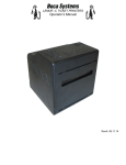
FSP 42/44/46 Flight Strip Printer
Technical Manual
Revision D: 04.18.08
BOCA SYSTEMS, INC.
©
2008 Boca Systems, Inc. All rights reserved.
Under the copyright laws, this manual may not be copied, in whole or in part, without
the written consent of BOCA.
Every effort has been made to ensure that the information in this manual is accurate.
BOCA is not responsible for printing or clerical errors and reserves the right to change
specifications without notice.
Table of Contents
Page
1.0
Introduction
1
2.0
Unpacking the Printer
2
3.0
A tour of your printer
3
4.0
Installation
7
4.1
Loading Flight Strips
7
5.0
Standard Configuration
9
5.1
This Section has been removed
15
5.2
Control Panel Indicators
18
6.0.
Interface Pinouts
19
7.0
Thermal Paper - Theory and Specification
20
8.0
Maintenance and Adjustments
21
8.1
Paper Guide and Print Head assembly
21
8.1.5 Optical Devices
21
8.1.5.5 Ticket Load Switch
22
8.1.6 Thermal Print Head
23
8.1.7 Rubber Drive Roller
23
8.2
Cutter Assembly
25
8.3
Logic Board
25
8.4
General Cleaning
25
9.0
Spare Parts List
26
10.0
Troubleshooting Guide
27
Table of Figures and Appendices
Figure 1
Packaging
Page
2
Figure 2a
Control Panel and LCD
3
Figure 2b
Flight Strip Printer(FSP)
3
Figure 2c
Cabinet Lock Mechanism
3
Figure 3a
FSP side view
4
Figure 3b
FSP, cover open
5
Figure 4
FSP, rear view
6
Figure 5
Adjustable paper path
7
Figure 6
Adjustable paper path instructions
7
Figure 7
Flight Strip Loading
8
Figure 8
Optical Device
22
Figure 8a
Ticket Load Switch
22
Figure 9a-c
Print head removal, cleaning and adjustment
24
FCC NOTICE
NOTE: The equipment has been tested and found to comply with the limits for a class
A digital device, pursuant to part 15 of the FCC rules. These limits are designed to
provide reasonable protection against harmful interference when the equipment is
operated in a commercial environment. This equipment generates, uses, and can radiate radio frequency energy and , if not installed and used in accordance with the
instruction manual, may cause harmful interference to radio communications.
Operation of this equipment in a residential area is likely to cause harmful interference
in which case the user will be required to correct the interference at his own expense.
Operation is subject to the following two conditions:
1. This device may not cause harmful interference, and
2. This device must accept any interference received, including interference that may
cause undesired operation.
NOTE: This unit was tested with shielded cables on the peripheral devices. Shielded
cables must be used with the unit to insure compliance.
i
WARRANTY INFORMATION
PRINTERS - BOCA warrants each printer to be free of defects for a period of one year
from the date of shipment when subject to normal use and service. This warranty covers all parts and labor except for the print head which is warranted for 90 days. All
warranty labor is to be performed at the BOCA facility. Equipment damaged by misuse
or negligence including damage to print heads caused by defective ticket stock is
excluded from this warranty.
Any defective equipment meeting these conditions should be returned to BOCA for
repair (freight prepaid) in its original box and packing material. A short note describing
the failure should be enclosed with the printer.
Equipment damaged in shipping should be reported immediately both to BOCA and to
the shipper.
ii
1.0 Introduction
The BOCA Flight Strip Printer, (FSP) is a direct thermal ticket printer with an integrated
cutting mechanism designed for air traffic control environments. This manual will
provide the user with general information regarding printer set-up, configuration and
troubleshooting. Please review your programming guide for additional details.
1
2.0 Unpacking the Printer
The printer is shipped in a ruggedized container. Please save packing material for
future use. Remove the printer (see figure 1) and accessories from the box and
inspect for obvious damage. If damage is noticed, please report it immediately to
BOCA.
Tel: (561) 206-0100 Fax: (561) 998-9609
[email protected]
The following items should be in the box:
a) Flight Strip Printer
b) Hopper (Optional)
c) AC power cord
Figure 1 - Packaging
2
3.0 A Tour of Your Printer
Figure 2a - Control Panel
and LCD
Output Slot
(Hopper Mounting
Holes)
Figure 2b - Flight Strip Printer (FSP)
Figure 2c - Cabinet Lock Mechanism
3
F
A
B
D
C
E
Figure 3a - FSP, Side View
A. Cutter Assembly
B. Optical Detector
C. Timing Belt
D. Drive Pulley (2)
E. Transformer
F. Print Head Release Lever
NOTE:
THE CUTTER ASSEMBLY MAY VARY
DEPENDING ON THE DATE OF
MANUFACTURE OF THE PRINTER.
THE SC2 CUTTER IS SHOWN.
4
B
A
C
Figure 3b - FSP, Cover Open
A. Print Head Release Lever
B. Logic Board
C. LCD Control Board
NOTE:
LOGIC BOARD CONFIGURATIONS MAY
VARY DEPENDING ON THE DATE OF
MANUFACTURE OF THE PRINTER.
THE FGL42 LOGIC BOARD IS SHOWN.
5
A
C
F
B
E
D
Figure 4 - FSP, Rear View
A. AC Power Connector
B. Fuse Holder (2amp,SB)
C. Input Slot
D. Interface Connector (Serial)
E. Locking Mechanism
F. ON/OFF Switch
NOTE:
CONFIGURATION MAY VARY
DEPENDING ON THE DATE OF
MANUFACTURE OF THE
PRINTER FGL42 LOGIC BOARD
CONFIGURATION SHOWN.
6
4.0 Installation
The FSP is designed to be mounted on a counter top or shelf. However, prior to site
preparation and installation, the printer should be powered up and run in the self test
mode. L ay the printer flat on a counter. Please confirm that the line voltage agrees with
the voltage listed on the label affixed to the side of the unit (see figure 4). Attach the
AC cord and serial/remote interface cables into the proper connectors as shown in
figure 4. Turn power on (figure 2) and you will hear the cutter motor cycle. The LCD
will display PAPER OUT.
4.1 Loading Flight Strips
Prior to loading strips, open cabinet lock mechanism (figure 2c) by inserting screwdriver and making one half turn. This printer is designed with an adjustable paper path feature. Flight strips measuring between 1.0 inches and 1.328 inches in width can be
accomodated.
Figure 5 - Adjustable paper path
1. Feed stock into the paper path.
2. Loosen thumb screws on slider.
3. Move slider towards the stock until they touch.
4. Back slider away from the stock a little (1/32”)
5. Tighten thumb screws
CAUTION:
Do not adjust slider tight against ticket
stock. This will cause a feed problem.
Flight Strips will move from side to side if
the slider is adjusted too far away from
the flight strips. This will cause a feed
problem.
Thumb Screws
Figure 6 - Adjustable paper path instructions
7
You may now install the printer in its permanent location. Adequate room should be
provided behind the printer for the smooth feeding of stock.
Begin loading flight strips through the entrance slot (figure 7) with a smooth motion
until the printer automatically positions the flight strip.
NOTE: Flight Strips should be loaded with the black mark facing down in the feed
direction shown below (figure 7).
FEED DIRECTION
THERMAL
ACTIVE SURFACE
Figure 7 - Flight Strip loading
NOTE:
THE PICTURE OF THE
ARROW ON THE BOTTOM
OF THE FLIGHT STRIPS
IS AN OPTIONAL GRAPHIC.
After the flight strip is automatically positioned (the READY LED will be illuminated),
press the TEST button located on the control panel (figure 2a) to print a test ticket.
Verify that the printer works properly with your system by issuing a ticket through your
computer system.
8
5.0 Standard Configuration
The FSP is factory configured for specific customer requirements using an enhanced
FGL package. Printing resolution is 300 dots per inch. For complete information on
the FGL Programming Language, please see the programming guide. FGL printers
allow the user to adjust various printer options through the control panel.
CHECK
PAPER
MENU
Selects proper menu topic
(baud rate, cut count, etc.)
PAPER
JAM
DATA
TEST
READY
CHOICES
Enters new value / Also
saves new values.
Scrolls through choices in
individual menu topics.
To access and use the FACTORY MENU, follow these steps:
1. Flight strip stock should be loaded into the printer. The LCD window displays
the firmware level installed in the printer.
2. Press both MENU and CHOICES switches simultaneously for about three seconds.
The LCD window displays FACTORY MENU! .
3. To scroll through the menu topic, use MENU stopping on the topic you wish to
change.
4. Press CHOICES to scroll through choices in the selected topic. NOTE: The
printer displays a blinking cursor for the values presently stored in the printer.
5. Once you have found the new value you want, press TEST. The LCD window
displays EXIT AND SAVE?. If you wish to save the new value, press TEST
again.
6. If you do not wish to save the new value, press MENU. The LCD window
displays JUST EXIT?. Press TEST to exit the FACTORY MENU without
saving new values or press MENU to enter back into the FACTORY MENU.
9
The chart below lists the present menu topics. These topics are subject to change.
The following is an overview of what
each Menu option does:
TEST TICKET TYPE?
The FSP allows one of four different test tickets to be printed when the printer’s test
button is pressed. In addition, this selection also determines other preset values
associated with the test ticket format selected.
PRINT HEAD TYPE?
Here are the following choices.
KYOCERA
TDK
Brown circuit board with black colored print surface.
Green circuit board with silver colored print surface. Default Value
BAUD RATE?
Controls the serial interface baud rate, parity bit, data bits and stop bits.
Here are the following choices:
1200,N,8,1
1200,E,7,1
1200,O,7,1
2400,N,8,1
2400,E,7,1
2400,O,7,1
4800,N,8,1
4800,E,7,1
4800,O,7,1
9600,N,8,1
9600,E,7,1
9600,O,7,1
19200,N,8,1
19200,E,7,1
19200,O,7,1
28800,N,8,1
28800,E,7,1
38400,N,8,1
38400,E,7,1
57600,N,8,1
57600,E,7,1
115200,N,8,1
115200,E,7,1
10
MINI/MICRO?
Defines the type of printer.
MINI Is for a printer with a Cutter Assembly (factory default)
MICRO Is for a printer without a Cutter Assembly
PRINT SPEED?
Controls the speed the ticket travels at. Also effects the print quality.
The numbers range from 0 - FASTEST to 7 - SLOWEST. 3 is factory default.
DIAGNOSTIC MODE?
Please consult your Programming Guide
Your choices are YES or NO. NO is factory default.
TICKET TYPE?
Defines how the optos are configured on the paper guide assembly.
NORMAL Both optos are inline with each other (usually mounted on a black bracket)
ATM Feed opto is mounted under the thermal head and cut opto is attached to the cutter
assembly.
LABEL Same as ATM but the cut opto is a see through type.
SPECIAL TICKET This option is for a printer with a ticket load switch. (factory default)
STATUS ENABLED?
Sets status response protocols.
Here are the following choices:
NONE
SERIAL
PARALLEL
SER/PAR
USB
USB/SER
USB/PAR
USB/SER/PAR
Disables the XON/XOFF and status response protocols
Enables the XON/XOFF and status response protocol for the serial port (factory default)
Enables bi-directional parallel statusresponses if printer is configured as bi-directional.
Enablesb both bi-directional parallel and serial status responses
Enables USB status responses
Enables USB and serial status responses
Enables USB and bi-directional parallel
Enables USB, bi-directional parallel and serial status responses
TRANSPARENT MODE?
Please consult your Programming Guide
Your choices are YES (Enabled) or NO (Disabled). YES is factory default.
PAPER MODE?
Is generally used only for test purposes. It may also be used on roll stock with no
black marks on the ticket.
Your choices are YES (Enabled) or NO (Disabled). NO is factory default.
HEAD DPI?
Defines thermal head dpi (dots per inch)
Your choices are 200 or 300. 300 is factory default.
11
SPECIAL HEAD?
Is used when a special paper path size is installed (2.125”, 2.5”, 2.7”...)
Here are the following choices:
NO
ON P1
ON P2
ON BOTH
REV ADJ2 P1
REV ADJ2 P2
REV ADJ BOTH
NO special head (factory default)
SINGLE PATH PRINTER ONLY. DUAL PATH PRINTER PATH #1
DUAL PATH PRINTER PATH #2
DUAL PATH PRINTER BOTH PATHS
DUAL & SINGLE PATH PRINTER WITH REV ADJ2 PATH ONLY
DUAL PATH PRINTER WITH REV ADJ2 PATH ONLY
DUAL PATH PRINTER WITH REV ADJ2 PATH ONLY
PATH TYPE?
Defines the number of paper paths used.
Here are the following choices:
PATH 1
PATH 2
DUAL
DUAL SUPPLY
VENTEK DUAL
Locks a Dual path printer onto path#1 (all single path printers) (factory default)
Locks a Dual path printer onto path #2
Is used for Dual path printer
Please consult your programming Guide (Dual Printer Supplement)
Special settings only used by certain customers.
BUFFER MODE?
Defines when the printer will go busy.
Here are the following choices:
SINGLE MODE 1
SINGLE MODE 2
MULTIPLE MODE
Go busy after each print command inserted in buffer
Go busy after receiving <p> command
Go busy when the input buffer is full (~4k) (factory default)
CLEAR DOWNLOAD?
Clears those items downloaded by the operator (PCX or softfonts).
Your choices are YES or NO.
DEFAULT SETTING
Resets the printer back to the factory default setting.
Your choices are YES or NO.
INC CUT1 COUNT?
Enables the operator to move the cut or tear position to the left (towards the ticket
entrance area). Cut counts are increments of .003” for 300dpi and .002” for 200dpi.
The count value is changed by depressing CHOICES.
16 is factory default.
DEC CUT1 COUNT?
Enables the operator to move the cut or tear position to the right (towards the ticket exit
area). Cut counts are decrements of .003” for 300dpi and .002” for 200dpi. The count
value is changed by depressing CHOICES. 16 is factory default.
12
INC CUT2 COUNT?
Same as INC CUT1 COUNT? but effects path #2 on a dual path printer.
(Does not apply)
DEC CUT2 COUNT?
Same as DEC CUT1 COUNT? but effects path #2 on a dual path printer.
(Does not apply)
2-SIDED PRINTER?
Only used with 2S ticket printers.
Your choices are YES (Enabled) or NO (Disabled). NO is factory default.
PARK TICKET?
Reverse the ticket to the print position after the last ticket in a group has been printed.
Please consult your Programming Guide. Your choices are YES (Enabled) or NO
(Disabled). NO is factory default.
TICKET MODE?
Defines how the printer will treat multiple tickets. Please consult your Programming
Guide. Your choices are SINGLE or MULTIPLE. MULTIPLE is factory default.
PRINT MODE?
Defines the automatic ticket length calculation feature.
THERMAL The printer will feed out and then retract a ticket during this measurement.
(factory default)
RIBBON The printer will feed out one blank ticket. This mode is used for label stock to
prevent peeling.
PRINT INTENSITY?
Controls the darkness of ticket print out.
Here are the following choices:
LIGHT
MED LIGHT
NORMAL
MED DARK
SHORT HEAD LIFE
(factory default)
SKI MODE?
Enables the operator to set an unprintable area on the first .50” of a ticket.
This is ideally used for label stock. Your choices are YES (Enabled) or NO (Disabled).
NO is factory default
13
FLASH ACK MODE?
Enables or disables an ACK being sent back to the host after a flash operation. Your
choices are YES (Enabled) or NO (Disabled). NO is factory default.
SOFTWARE BUSY?
Defines if the printer will go busy after each byte is received. Your choices are YES
(Enabled) or NO (Disabled). NO is factory default.
BI-DIRECTIONAL?
Enables or disables the Bi-Directional parallel interface protocol. Your choices are YES
(Enabled) or NO (Disabled). NO is factory default.
TEST TICKET?
This item is used to select various FGL test ticket formats, it has been redefined for
NAV Canada and should not be changed. Please refer to the first menu item “TEST
TICKET TYPE?”.
BASEBALL MODE?
Defines the type of software emulation protocol for certain Baseball teams in the US.
This feature is set at the factory and should not be changed. NO is factory
default
USB?
Only used for printer with USB interface connector.
Your choices are YES (Enabled) or NO (Disabled). NO is factory default.
MAGNETICS?
Defines if a printer is set up for magnetics. Your choices are YES (Enabled) or NO
(Disabled). This feature is set at the factory and should not be changed. NO is
factory default.
EXIT AND SAVE !
Will save any changes made to the above menu options.
If you wish to save the new value then press TEST, if not press MENU.
JUST EXIT?
Will exit the menu options without saving any changes.
If you with to exit without saving the new value then press TEST, if not press MENU.
14
5.1 THIS SECTION HAS BEEN REMOVED
This page has been left blank intentionally
15
5.2 Control Panel Indicator
Status Patterns (Flashing). Flashing errors have equal
on and off time.
Error No.
Description
Ready
Data
1
Flash erase operation incomplete
ON
OFF
OFF
ON
OFF
OFF
2
3
4
5
6
7
8
9
10
11
12
13
14
15
Flash Vpp problem
Flash byte erase error
Flash Sequence error
Flash block erase error
Bad flash
Flash program operation incomplete
Flash byte program error
Memory is full
Need a reclaim
Soft font download error
Delete file error
Not assigned
Not assigned
Not assigned
ON
ON
OFF
ON
OFF
ON
OFF
ON
OFF
ON
OFF
ON
ON
OFF
ON
ON
Paper
Jam
Out of
paper
OFF
OFF
OFF
OFF
OFF
ON
ON
ON
ON
ON
OFF
OFF
OFF
OFF
OFF
ON
ON
ON
OFF
OFF
ON
OFF
ON
ON
ON
OFF
OFF
OFF
OFF
ON
ON
ON
ON
ON
ON
ON
ON
ON
Status Patterns (Flickering). Flickering errors have much longer
on time than off time.
Error No.
Description
Ready
Data
Paper
Jam
Out of
paper
1
2
3
Ribbon problem
Processor fault
Stepper timeout error
ON
OFF
ON
OFF
ON
ON
OFF
OFF
OFF
OFF
4
5
6
7
8
9
10
Paper jam
Not assigned
Not assigned
Not assigned
Not assigned
11
Not assigned
RAM failure
ROM failure
14
15
Check optos
Not assigned
Power-up initialization problems
12
13
Cutter failure
OFF
ON
OFF
ON
OFF
ON
OFF
OFF
ON
ON
OFF
ON
OFF
OFF
ON
ON
OFF
ON
OFF
ON
ON
OFF
ON
OFF
ON
ON
ON
ON
OFF
OFF
OFF
OFF
OFF
OFF
OFF
OFF
OFF
ON
ON
ON
ON
ON
ON
ON
ON
ON
ON
ON
ON
ON
18
6.0 Interface Pinouts
Serial Pinouts
RS232 (Standard)
Pin
Function
2
3
7
5,20
4,22
Printer Transmit
Printer Receive
Ground
DTR (Printer Ready)
RTS (+5Vdc)
Typical RS232 Pin Connections
(Standard)
9 PIN PC
(Standard)
25 PIN PC
BOCA
2
3
7
20
20
20
CPU
3 RXD
2 TXD
7 GND
6 DSR
5 CTS*
8 CD*
BOCA
2
3
7
20
20
20
CPU
2 RXD
3 TXD
5 GND
6 DSR
1 CD*
8 CTS*
* Optional Connection
Parallel Pinouts
Pin
1
2-9
10
11
12
15
18
Function
Strobe (negative)
DATA (DBØ - DB7)
ACK (negative)
BUSY
PAPER OUT
ERROR (negative)
Ground
19
7.0 Thermal Paper - Theory & Specification
The print head’s life expectancy is composed of both a mechanical and an electrical component. Both of
these factors are strongly influenced by the quality of the thermal paper used.
MECHANICAL
The print head has a theoretical rating of 60 kilometers. This number is based upon the assumption that
the head will be used with a good quality, top coated thermal paper. Uncoated and poorly top coated
thermal papers are abrasive to the print head and have been found to wear through the head after less
than one kilometer.
Other factors which may contribute to premature mechanical wear are the use of non-thermal inks and
stray metallic particles stuck in ticket perforations. Certain inks colors such as opaque white (which contains titanium dioxide) are also highly abrasive.
Unfortunately, there are no available devices for quantitatively measuring the abrasiveness of a given
ticket. Fortunately, we have developed a slightly subjective, but effective method of weeding out overly
abrasive ticket stock.
ELECTRICAL
Each heat element, dot, on the print head has a theoretical life expectancy of 100 million activations.
This is based on the assumption that each activation will cause the dot temperature to approach the
dot’s maximum recommended temperature. Running at lower temperatures will increase the theoretical
life expectancy, while slight temperature increases will seriously (exponentially) degrade the head life.
The thermal paper can affect the electrical head life in two ways. Insensitive, slow to image papers, will
typically encourage the user to increase the voltage to darken the printed image. This will directly
increase the head temperature resulting in reduced head life. Additionally, the higher temperatures will
frequently cause the ink to peel off the ticket and deposit onto the print head. The ink debris will disrupt
the normal transfer of heat from the head to the paper. This further increases the head temperature
above the desired level. The use of non-thermal inks and/or non-top coated papers also will cause the
ink to release and deposit on the print head.
SPECIFICATION
Based upon the above technical information, BOCA has always tried to encourage our customers to use
the proper thermal papers to maximize the life of their print heads. BOCA provides an extensive series
of papers which meet the above criteria for low abrasion and high sensitivity. We have also tested and
approved a number of Ricoh thermal papers which meet our criteria. While we have not had the opportunity to test other manufacturers’ thermal papers, we feel confident that other papers manufactured with
the above goals in mind should be acceptable for use in our printers. The following list of papers have
been approved by BOCA.
300 dpi usage
BOCA
HS7
Please note that the 300 dpi papers may be used on 200 dpi printers. In fact, doing so will increase the
electrical life of the head as this will allow the head to operate at a lower temperature. DO NOT use 300
dpi heads with 200 dpi paper.
20
8.0 Maintenance and Adjustments
Your ticket printer is solidly constructed and has been designed for high volume use. It
requires minimal care to provide maximum service.
This section provides an overview of printer maintenance, including part alignments,
adjustment and replacement.
For discussion purposes, the printer consists of three major modules or assemblies:
• Paper guide and print head assembly
• Cutter assembly
• Logic board assembly
As a safety precaution, all service to the printer should be done with power off
and the AC cord unplugged from the printer.
8.1 Paper Guide and Print Head Assembly
The principal function of this assembly is to guide the flight strip stock to the thermal
print head where thermal printing takes place. Additionally, this assembly houses the
drive platen, optical detector and ticket load switch. If necessary, the total assembly
can be removed from the unit. However, all replacements and adjustments of the components of this assembly can be done without removing the total assembly. The most
common adjustments and replacements regarding this assembly follows:
8.1.5 Optical Device (see figure 8)
There is one opto device mounted on an aluminum bracket beneath the paper guide.
The opto controls ticket cut position. Removal or adjustment of the opto should be
done without removing the bracket from the paper guide.
The opto position is factory set and adjustment should not be necessary.
Caution: Before making any opto adjustments make sure your flight strip stock
was manufactured to proper specifications. The printer should cut the ticket just
behind the perforation. The ticket should never be cut in front of the perforation.
The position of the cut can be controlled by changing the cut count setting in the
OPERATOR MENU (see Section 5.0 - Standard Configuration).
Once a year the optos eyes should be blown off with air. This interval will vary depending upon the environment and the quality of the ticket stock.
21
FEED DIRECTION
Optical Device, Ticket Cut
Paper Guide
5
/64”
Allen Head
Screws
On some models these
connectors plug into the
back of the circuit board
Grn/Red/Blk
Wires
TO LOGIC
BOARD
Figure 8 - Optical Device
8.1.5.5 Ticket Load Switch
The ticket load switch should be positioned such that the printer automatically activates
the stepper motor at the proper time when tickets are loaded into the printer. When
loading tickets, the stepper motor should turn on when the ticket stops in front of the
thermal head. At this point, the ticket will be grabbed out of your hand and fed into the
printer. If the motor does not activate, make sure the ticket stock is loaded into the
printer properly.
Figure 8a - Ticket Load Switch
(Print Head removed)
22
8.1.6 THERMAL PRINT HEAD
The print head should be cleaned periodically to prevent debris from building up on the
print element. The required cleaning interval varies greatly depending on the quality of
the ticket stock and the amount of dust entering the print area. Excessive dirt build up
on the print head will result in reduced quality. Continuing to run the print head in a
dirty condition will reduce its life expectancy as it is unable to diffuse its heat properly.
There are two pressure adjustment set screws (10-32 x 1⁄8) located in the spring plate
above the print head. (See Figure 9a) Athough these set screws are factory set, the
pressure can be adjusted for a variance in paper thickness or to fine tune after a print
head has been replaced.
The thermal print head can be removed for cleaning or replacement, as follows:
(Please refer to figures 9a - c)
1. Make sure power is off and the AC cord is disconnected from the printer.
2. DO NOT UNPLUG CABLE FROM PRINT HEAD.
3. Lift up the print head release lever (located above the head mounting block) to
remove pressure from the thermal head. (see figure 9a)
4. Lift up the head mounting block/thermal head to remove. (see figure 9b)
5. Clean the thermal print head surface (the side that makes contact with the paper)
with isopropyl alcohol. (see figure 9c)
6. Install the head by reversing the above procedures. For printers with Boca cutter assembly
make sure the thermal head goes under the cutter assembly. (see figure 9d) Make sure print
head is not installed improperly (see figure 9e)
7. Restore pressure to the head by pushing down on the cam lock assembly. You shouldn’t
have to use excessive force to lock the cam lock assembly in place.
8. The printer in now ready for operation. If the print quality is still poor then the
thermal head needs to be replaced.
9. To replace print head remove ribbon connector from print head and then remove
print head from mounting block by removing two unmarked screws. (see figure 9b)
8.1.7 Rubber Drive Roller (Platen)
The rubber drive roller should be cleaned once a year to prevent paper dust from
building up on the roller. Clean drive roller with a paper towel and alcohol.
1. Unlock the thermal head and tilt back to gain access to platen.
2. Clean the full length of the platen.
3. Rotate the platen clockwise and repeat step 2, continue in the same manner for
one full revolution of the platen.
4. Close or lock the thermal head. Printer in now ready for normal operation.
23
Print Head release lever.
Adjustment set screws
Figure 9a - Print Head removal
Remove these two unmarked screws to
replace print head.
Figure 9b - Print Head removal
.
Figure 9c - Print Head removal
Clean this surface
Figure 9d
Head is installed wrong. Should
no be sitting on top of the cutter.
Figure 9e
24
8.2 Cutter Assembly
NOTE:
THE CUTTER ASSEMBLY MAY VARY DEPENDING ON THE DATE OF
MANUFACTURE OF THE PRINTER
8.2a SC Cutter Assembly (SC2)
The SC cutter (SC2) system is a fully integrated rotary cutter mechanism powered by
a DC motor. The SC2 requires no adjustments and is rated for approximately 750,000
cuts.
8.2b Boca Cutter Assembly (BC2)
The BOCA cutter (BC2) system is a fully integrated recipricating cutter mechanism
powered by a stepper motor. The BC2 requires no adjustments and is rated for
approximately 750,000 cuts.
When first powering up the printer, be aware of the following:
Wait five seconds before feeding ticket stock into the printer after power up. During this
time the cutter will cycle once. If ticket stock is fed into the printer before five seconds,
a ticket jam could occur.
The cutter should be blown out with air periodically to prevent debris from building up
inside the cutter area. The required cleaning interval varies greatly depending on the
quality of the ticket stock and the amount of paper dust entering the cutter area.
8.3 Logic Board
The printed circuit boards used in this product have been manufactured using surface
mount technology. These printed circuit boards cannot be effectively repaired in the
field and should be returned to the manufacturer if repair is required.
Your printer has one large printed circuit board which houses all control and power
supply circuitry. ALL SERVICE SHOULD BE DONE WITH POWER OFF AND THE
AC CORD UNPLUGGED FROM THE PRINTER.
8.4 General Cleaning
The interior of the printer should be cleaned whenever there is a visible accumulation
of dust. Use a small vacuum for cleaning. Be careful not to jar any of the printer’s
parts loose.
25
9.0 PARTS LIST
ITEM
Part Numbers
Description
1
2
3
4
5
6
7
8
9
10
11
12
13
14
15
16
17
18
19
20
21
22
23
24
25
26
27
28
29
30
31
32
33
34
35
36
37
38
39
40
41
42
43
44
45
46
47
48
49
50
51
52
53
54
55
423182
423182CV
423111FSP
421366FSP
421367FSP
422468FSP
423182-1
420947FSP
423170FSP
421428FSP
426816VMINISC2
420816FSP
423142-X
422234
P49-1011
P49-1012
422764
421609-1SS
421585FSP
422888-115
3002
421671-1
P31-1001
422920-PC
P29-1005
421607-5M4
421609-5M4
421609-1SS
P49-1006
422264
421359-1TOH
423236
421772
423072-5M2
422560-5
FGL42
421639-4
P28-1015
P33-1006
422810
422371-1
P50-1003
P51-1014
P51-1011
423124
422559-13
422559-9
422892
P19-1005
422590
423455
FGL44
X44
X46
Q46
CABINET, FSP
COVER, FSP
PRINT CAGE, FSP
PAPER GUIDE, FSP (LOWER)
PAPER GUIDE, UPPER
BEZEL
FRONT PLATE, FSP
CONNECTOR PLATE
SWITCH XFER PLATE
BKT, OPTO MNTG
CUTTER MNTG PLATE (SC2 ONLY)
BLOCK, CUTTER SPACER (SC2 ONLY)
GLASS RETAINER
PLATEN, FSP
1
⁄4 TURN FASTENER
RECEPTACLE, FASTENER
MICRO SWITCH
SHAFT, ADJ P/G
COVER, GEAR BOX
TRANSFORMER
PRINT HEAD, 2” 300 DPI
LCD/CONTROL PANEL ASSEMBLY
AC FILTER/POWER SWITCH
INTERFACE BOARD, PC SERIAL
FUSE, 2 AMP SLO-BLO
BLOCK, ADJUSTABLE GUIDE
SLIDE, ADJUSTABLE GUIDE
SHAFT, ADJUSTABLE GUIDE (2 PER UNIT)
THUMBSCREW, ADJUSTABLE GUIDE (2 PER UNIT)
OPTICAL DETECTOR
HEAD MOUNTING BLOCK ASSEMBLY
CAM, HEAD PRESSURE
CAM SHAFT
SPACER, PRINT CAGE (2 PER UNIT)
DECAL, CONTROL PANEL
LOGIC BOARD, FGL42
CUTTER ASSEMBLY (SC2)
SILENT CUTTER MICRO SWITCH (SC2 ONLY)
SILENT CUTTER MOTOR (SC2 ONLY)
SILENT CUTTER MOTOR GEAR BOX (SC2 ONLY)
SILENT CUTTER PINION GEAR (SC2 ONLY)
DRIVE BELT, 102T
DRIVE PULLEY, 20T (SMALL ID 5mm)
DRIVE PULLEY, 30T
CABLE RIBBON, DATA CABLE SERAIL
CABLE RIBBON, CONTROL PANEL 13”
CABLE RIBBON, CONTROL PANEL 9”
HARNESS, AC
HARNESS, DC
STEPPER MOTOR
BOCA CUTTER ASSY (BC2)
LOGIC BOARD, FGL 44
LOGIC BOARD, X44
LOGIC BOARD, X46
LOGIC BOARD, Q46
26
10.0 Troubleshooting Guide
This is a simplified troubleshooting guide listing some of the typical problems. It is not intended
to provide technical details or repair methods, but can serve as a guide for fault isolation in the
field. If you need additional help, please contact BOCA at
Tel: (561) 998-9600 Fax: (561) 998-9609
1.
2.
3.
4.
5.
6.
NO OPERATION, POWER INDICATOR IS OUT
a. Check the power cord for proper installation at both ends.
b. Check main fuse and replace if blown. (2amp, 250 volt, SB)
c. Check that there is power at the AC receptacle.
POWER IS ON BUT NO OPERATION
a. Check all electrical connections on the printer.
b. If cutter motor does not rotate after power up, See # 6.
c. Unplug the thermal head and turn on the printer.
If printer works, replace the thermal head.
d. Replace the Main logic board.
POWER IS ON BUT TICKET WILL NOT LOAD
a. See # 2
b. Make sure the print head/cam lock assembly is fully locked in the closed position.
Consult “Thermal Print Head” in Section 8.1.6.
c. Check that the ticket stock is being loaded correctly.
d. Replace ticket load switch.
e. Replace ticket cut opto.
f. Replace the Main logic board.
ERRATIC CUT POSITION
a. Check for defective ticket stock. Is the black mark unevenly spaced apart or
light in color? Is the ticket too wide for the paper path?
b. Clean off opto eyes. Consult “Optical Device” in Section 8.1.5.
c. Check that the platen is clean. Consult “Rubber Drive Roller” in Section 8.1.7.
d. Replace ticket cut opto.
e. Replace ticket load switch.
g. Replace the Main logic board.
ERRATIC PRINT POSITION
a. See # 4
CUTTER DOES NOT CYCLE
a. Check for blockage in the cutter area.
b. Make sure printer is set for MINI. Consult Section 5.0
c. Replace the cutter assembly
d. Replace the Main logic board.
27
7.
8.
9.
10.
11.
12.
POOR PRINT OUT (light print out)
a. Make sure the print head/cam lock assembly if fully locked in the closed position.
b. Consult “Thermal Print Head” in Section 8.1.6.
c. Adjust print intensity setting via the control panel. Consult Section 5.0
d. Replace thermal head.
POOR PRINT OUT (white voids in print out)
a. Clean print head. Consult “Thermal Print Head” in Section 8.1.6.
b. Replace thermal head.
NO PRINT OUT
a. Check head cable for electrical connection at both ends
b. Check to make sure head cable is plugged in properly into the thermal head.
c. Replace the thermal head.
d. Replace the Main logic board.
PRINTER SKIPS TICKETS WHILE PRINTING
a. Check all electrical connections on the printer.
b. Check position and quality of black mark on the ticket stock.
c. Clean off opto eye. Consult “Optical Device” in Section 8.1.5.
d. Replace ticket cut opto.
e. Replace ticket load switch.
PRINTER SKIPS TICKETS AND DIES
a. See # 9.
TICKET JAM ENTERING THE CUTTER AREA
a. Check all electrical connections on the printer.
b. Replace cutter assembly.
28