1
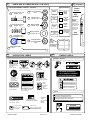
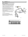
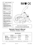
2
1
OPTIONAL ACCESSORIES
VACUUM HOSE KIT
P/N 830255 5" (127mm) x 8'
(2.4m) For vacuuming in
hard-to-reach areas.
HOSE COUPLER KIT
P/N 800334
5" (127mm) For coupling
multiple hoses together to
increase vacuuming distance.
RIDE ON CHARIOT KIT
P/N 830257
Reduces operator fatigue.
Operator stands while riding
behind vacuum. Maximum
load 300 lbs.(136 kg)
ALTERNATE DEBRIS BAGS
STANDARD DEBRIS BAG
P/N 830320 Standard on
VQ models. For dusty
conditions.
TURF DEBRIS BAG
P/N 830282 For use in
leaves and grass in nondusty conditions.
BAG COVER
P/N 830284 Directs dust
downward away from
operator.
Thank You for Selecting
The Powerful VQ QUIET VACUUM
Operator Owner's Manual
Self Propelled Models
VQ802SPH, VQ1002SP
Specifications
3
ENGINE: HP
ENGINE: TYPE
ENGINE: FUEL CAP.
ENGINE: OIL CAP.
WEIGHT: UNIT
WEIGHT: SHIPPING
ENGINE: WEIGHT
UNIT SIZE:
OVERALL LENGTH: 66" (1.68m)
(Note: B&S = Briggs & Stratton,
Part No. 830542
VQ1002SP
VQ802SPH
10 (7.45 kW)
B & S INTEK
4 qt. (3.8 L)
0.875 qt. (0.8 L)
282 lb (127.9 kg)
314 lb (142.4 kg)
52 lb (23.6 kg)
8 (5.97 kW)
HONDA OHV
6.4 qt. (6.1 L)
1.16 qt. (1.1 L)
278 lb (126.1 kg)
310 lb (140.6 kg)
48.5 lb (22.0 kg)
OVERALL WIDTH 32.75" (0.83m)
OVERALL HEIGHT43.5" (1.10m)
Honda = American Honda
Page 1 of 16
Form No. F021302G
IN THE INTEREST OF SAFETY
5
BEFORE STARTING ENGINE, READ AND UNDERSTAND THE “ENTIRE OPERATOR'S MANUAL &
ENGINE MANUAL.”
THIS SYMBOL MEANS WARNING OR CAUTION. DEATH, PERSONAL INJURY AND/OR PROPERTY
DAMAGE MAY OCCUR UNLESS INSTRUCTIONS ARE FOLLOWED CAREFULLY.
WARNING: The Engine Exhaust from this product contains chemicals known
to the State of California to cause cancer, birth defects or other reproductive harm.
WARNING: DO NOT
1. DO NOT run engine in an enclosed area.
Exhaust gases contain carbon monoxide, an
odorless and deadly poison.
2. DO NOT place hands or feet near moving
or rotating parts.
3. DO NOT store, spill or use gasoline near
an open flame, or devices such as a stove,
furnace, or water heater which use a pilot
light or devices which can create a spark.
13. DO NOT tamper with governor springs,
governor links or other parts which may
change the governed engine speed.
14. DO NOT tamper with the engine speed
selected by the engine manufacturer.
15. DO NOT check for spark with spark plug
or spark plug wire removed. Use an
approved tester.
16. DO NOT crank engine with spark plug
removed. If engine is flooded, place throttle
in “FAST” position and crank until engine
starts.
4. DO NOT refuel indoors where area is not
well ventilated. Outdoor refueling is recommended.
17. DO NOT strike flywheel with a hard
object or metal tool as this may cause
flywheel to shatter in operation. Use proper
tools to service engine.
5. DO NOT fill fuel tank while engine is
running. Allow engine to cool for 2 minutes
before refueling. Store fuel in approved
safety containers.
18. DO NOT operate engine without a
muffler. Inspect periodically and replace, if
necessary. If engine is equipped with
muffler deflector, inspect periodically and
replace, if necessary, with correct deflector.
6. DO NOT remove fuel tank cap while
engine is running.
7. DO NOT operate engine when smell of
gasoline is present or other explosive
conditions exist.
19. DO NOT operate engine with an
accumulation of grass, leaves, dirt or other
combustible material in the muffler area.
8. DO NOT operate engine if gasoline is
spilled. Move machine away from the spill
and avoid creating any ignition until the
gasoline has evaporated.
20. DO NOT use this engine on any forest
covered, brush covered, or grass covered
unimproved land unless a spark arrester is
installed on the muffler. The arrester must
be maintained in effective working order by
the operator. In the State of California the
above is required by law (Section 4442 of
the California Public Resources Code).
Other states may have similar laws. Federal
laws apply on federal lands.
9. DO NOT transport unit with fuel in tank.
10. DO NOT smoke when filling fuel tank.
11. DO NOT choke carburetor to stop
engine. Whenever possible, gradually
reduce engine speed before stopping.
12. DO NOT run engine at excessive speeds.
This may result in injury & /or damage to
7
unit.
21. DO NOT touch hot muffler, cylinder, or
fins because contact may cause burns.
22. DO NOT run engine without air cleaner
or air cleaner cover.
23. DO NOT operate during excessive
vibration!
24. DO NOT leave machine unattended
while in operation.
25. DO NOT park machine on a steep grade
or slope.
WARNING: DO
1. ALWAYS DO remove the wire from the
spark plug when servicing the engine or
equipment TO PREVENT ACCIDENTAL
STARTING.
2. DO keep cylinder fins and governor
parts free of grass and other debris
which can affect engine speed.
3. DO pull starter cord slowly until resistance is felt. Then pull cord rapidly to avoid
kickback and prevent hand or arm injury.
4. DO examine muffler periodically to be
sure it is functioning effectively. A worn or
leaking muffler should be repaired or
replaced as necessary.
5. DO use fresh gasoline. Stale fuel can
gum carburetor and cause leakage.
6. DO check fuel lines and fittings frequently
for cracks or leaks. Replace if necessary
7. Follow engine manufacturer operating
and maintenance instructions.
8. Inspect machine and work area before
starting unit.
SOUND
8
Sound tests conducted were in accordance with 2000/14/EEC
and were performed on 2/14/2002 under the conditions listed:
6
TABLE OF CONTENTS
SAFETY INSTRUCTIONS
PARTS BAG & CONTROLS
LABELS
GENERAL SAFETY
PACKING CHECKLIST
ASSEMBLY
OPERATION
PARTS DRAWING & LIST
MAINTENANCE
TROUBLESHOOTING
WARRANTY PROCEDURE
○
○
○
○
○
○
○
○
○
○
○
○
○
○
○
○
○
○
○
○
○
○
○
○
○
○
Part No. 830542
○
○
○
○
○
○
○
○
○
○
○
○
○
○
○
○
○
GENERAL CONDITION:
Sunny
Sunny
GENERAL CONDITION:
○
○
○
○
○
○
○
Sound level of 88 dBA at operator position
Vibration levels at the operators handles were
measured in the vertical, lateral, and longitudinal
directions using calibrated vibration test equipment.
Tests were performed on 07/02/97 under the
conditions listed:
○
○
○
○
2
3
3
4
4
5
6, 7, 13
8 - 12
14 - 15
16
16
○
○
○
○
○
○
○
○
○
○
○
○
○
○
○
○
○
○
○
○
○
○
○
○
NOTE: Sound power level listed is the highest value for any model in this manual. Please
refer to serial plate on the unit for the sound power level for your model.
VIBRATION
VIBRATION LEVEL 1.9 g
TEMPERATURE:
○
○
○
WIND SPEED:
108 dB
MODEL: VQ1002SP
50° F (10° C)
15 MPH (24.1 kmh)
WIND DIRECTION:
North
HUMIDITY:
32 %
BAROMETRIC PRESSURE:
Page 2 of 16
30.06" Hg (764mm Hg)
TEMPERATURE:
WIND SPEED:
80° F (26.7° C)
10 MPH (16.1 kmh)
WIND DIRECTION:
East
HUMIDITY:
43 %
BAROMETRIC PRESSURE:
29.91" Hg (760mm Hg)
Form No. F021302G
12
13
PARTS BAG & LITERATURE ASSY P/N 830531
PARTS BAG ASSEMBLY CHECKLIST
Screw Cap 1/4-20 x 1 1/4
113
8041007 Qty. 2
Screw Cap 5/16-18 x 3/4
8041026 Qty. 3
Owner's
Manual
Nut Lock 1/4-20 8160001
Qty. 2
131
Nut Lock 5/16-18
8160002 Qty. 3
132
117
Literature Checklist
P/N 830204
Literature
VQ
Accessories
Check
Check
Washer 5/16 SAE
8172008 Qty. 3
140
Check
Warranty
Card
Check
EU Declaration
of Conformity
& EU
Distributor List
Washer 1/4 Flat Cut
Qty. 6
143 8171002
Rod End Ball Joint
Qty. 2
Owner's
Manual
830016
Literature
VQ
Accessories
830209
Warranty
Card
400972
EU Declaration
of Conformity &
EU Distributor
List 830321
CONTROLS
Throttle
Control
Stop
position
Briggs and
HONDA
engines have
a choke type
carburetor that
is operated
using choke
lever on side
of engine.
Start
position
STOP
SLOW
FAST
7 3 5/16-24 400873
35
Nut Regular 5/16-24
(Fine Thread) 8149002
Qty. 2
138
Gasket
Flange
Transition VQ
P/N 830160
(not to scale)
900407 TY-Wrap Cable
4 4 1" Qty. 4
14
15
INSTRUCTION LABELS
These labels should be included on your Vacuum. If any of these labels are damaged, replace them before putting this
equipment into operation. Item and part numbers are given to help in ordering replacement labels..
ENGINE LABELS
Briggs & Stratton
EXPLOSIVE FUEL
400268
WARNING
STOP ENGINE AND ALLOW TO
COOL BEFORE REFUELING.
ON
Label Do Not Fill
While Engine Is Hot
Item 130
Part No.400268
Debris Bag
Label item 50
THIS ENGINE EQUIPPED WITH
LOW OIL SENSOR, IF ENGINE WILL
NOT START, CHECK OIL LEVEL
810736
READ OWNER'S MANUAL
Label Read
Owner's Manual
tem No.181
Part No. 890301
USE PROTECTION
Label Danger Flying
Material Item 101 Part No.
810736
EXHAUST ELBOW IS ATTACHED.
EXHAUST IS DISCHARGING INTO
ENCLOSED CONTAINER.
HOSE IS ATTACHED.
ALL GUARDS ARE ATTACHED.
OPERATING INSTRUCTION IS OBTAINED.
830138
BEFORE OPERATING, MAKE SURE:
HOSE
CLOSED
890254
STOP ENGINE AND ALLOW T O
COOL BEFORE REFUELING.
KEEP ENGINE CLEAN OF DEBRIS.
INSPECT MACHINE BEFORE EACH USE AND REPLACE ANY
WORN AND DAMAGED PARTS.
PROPERLY SECURE EQUIPMENT BEFORE TRANSPORTING.
NEVER SERVICE UNIT WITHOUT DISCONNECTING SPARK PLUG WIRE.
USE ONLY A QUALIFIED MECHANIC TO SER VICE THIS MACHINE.
830196
Label Ear Eye
Breathing Item No.180
Part No. 890254
ABRASIVE DEBRIS WILL SHORTEN UNIT LIFE.
HOSE
OPEN
Label Caution Item 159
Part No.830138
Gasoline is flammable. Allow engine
to cool at least 2 minutes before fueling.
Engines emit carbon monoxide,
DO NOT run in enclosed area.
Honda
READ OWNER’S MANUAL BEFORE OPERATION.
LIRE LE MANUEL D UTILISATEUR AVANT USAGE.
VOR INBETRIEBNAHME UNBEDINGHT BEDIENUNGSANLEITUNG DURCHLESEN.
NO UTILIZAR SINANTES NO HABER LEIDO EL MANUAL
900327
830503
830502
Label Oil Chain
Item 111 Part
No. 830502
OFF
ON
Label Speed
5
Control
Item 150
4
Part No.
830237
3
830237
Label Danger Guards
Item 89 Part No. 900327
Label Clutch VQ Item
106 Part No. 830503
Read and follow Operating
Instructions before running engine.
Label
Diverter
Instructions
Item 99
Part
No.830196
WARNING
RELEASE TO DISENGAGE CLUTCH
PULL TO ENGAGE CLUTCH
Part No. 830542
CHOKE
OFF
Label Danger Keep
Hands and Feet Away
Item 100 Part No.400424
DANGER
OIL CHAIN
EVERY 10 HOURS
RUN
Label On Off
Item 112 Part No.830276
SP Honda Models Only
Page 3 of 16
HONDA MOTOR CO. , LTD. MADE IN JAPAN
OIL ALERT
2
1
WHEN OIL LEVEL LOW,
ENGINE STOPS IMMEDIATELY.
N
R
Form No. F021302G
GENERAL SAFETY
9
For your safety and the safety of others, these directions should be followed:
Do not operate this machine without first reading
owner's manual and engine manufacturer's manual.
Use of Ear Protection is recommended while
operating this machine.
Use of Eye and Breathing protection is recommended when using this machine, especially in dry
and dusty conditions. Optional bag cover directs dust
toward ground, away from the operator.
·DO NOT place hands or feet inside nozzle intake opening,
near debris outlet or near any moving parts.
·DO NOT start engine without debris bag and quick disconnect connected firmly in place to exhaust outlet.
·DO NOT start or operate machine with debris bag zipper
open.
11
·DO NOT operate during excessive vibration.
·DO NOT remove bag until engine has been turned off and has
come to a complete stop.
·DO NOT remove hose kit cap on nozzle until engine has been
turned off and has come to a complete stop.
·DO NOT operate machine with hose cap, bag or hose removed.
·DO NOT use this machine for vacuuming exclusively sand,
dust, fine dirt, rock, glass, string like material, grain, rags,
cans, metal, bark or water.
·DO NOT operate this machine on slopes greater than 20%.
·DO NOT pick up any hot or burning debris, or any toxic or
explosive material.
·DO NOT allow children to operate this equipment.
PACKING CHECKLIST
These items should be included in your carton. If
any of these parts are missing, contact your dealer.
Boxing Checklist
Check
Debris
Bag
830170A
Check
Elbow
Assembly
830159
Upper Handle
Assy Per Model
Check
SP
units
only
Check
Check
Check
QUICK DISCONNECT
Parts Bag
& Literature Assy
Main Unit
Briggs Models
830011.
Honda Models
830012.
Deflector
Assembly
830280
Rod Door
Nozzle
830286
Parts Bag &
Literature Assy
830531
Per Model
Check
Briggs & Stratton
Intek 10 HP
Engine
Manual
Per Model
Fig. 5
Denotes parts found in Parts Bag Assembly (shown on page 4).
Part No. 830542
Page 4 of 16
Check
Honda 8 HP GX240
Form No. F021302G
10
ASSEMBLY
Read all safety and operating instructions
before assembling or starting this unit.
48
PUT OIL IN ENGINE BEFORE STARTING.
Your Billy Goat is shipped from the factory in one carton, completely assembled except for the debris bag, deflector assy, upper
handle assembly, rod nozzle door, elbow assy.
73
138
47
1. UPPER HANDLE (item 41). Assemble securely to lower handle
stubs (item 37) and handle brace (item 36), using screws
(item
120 & 121), so that screw heads are on inside of handle. Otherwise, premature bag wear could result.
2. NOZZLE DOOR CONTROLS. Assemble ball joints (item 73),
jam nuts (item 138), to both ends of rod (item 47). Do not fully
tighten jam nuts.
Using screw (item 113), washer (item 143) and lock nut (item 131),
connect one end of rod (item 47) to nozzle door mounting. (See
Figure 5). Using rod, pull nozzle door open horizontal to ground
and hold opposite end of rod next to mounting hole on remote
lever (item 48), already assembled onto upper handle. (See Figure
1). If necessary, adjust rod length using threads provided on rod.
Adjust rod length to give a minimum of 1.0" (25.4 mm) hand
clearance between lever & maximum forward throttle position
when door is open. Assemble upper end of rod to lever on handle
using same hardware item numbers as shown above. (See figure
1& 2). Tighten jam nuts.
3. EXHAUST ASSY. Place flange gasket (item 35) onto housing of
main unit and assemble exhaust elbow to housing using screws
(item 117), washers (item 140) and lock nuts (item 132), provided
in parts bag. The rear hole mounts deflector (item 118), using
screw assembly (already attached to deflector) and lock nut (item
132). Bend opposite end of deflector down until notch in rear of
deflector catches onto handle brace (item 36) (see figure 3).
4. DEBRIS BAG (Item 50) (see figure 4).
4.1 Unfold and place mouth of bag over exhaust elbow, completely covering the discharge opening with bag neck straps,
placing one on each side of elbow flange.
COMPLETELY TIGHTEN BAG NECK STRAPS
4.2 Attach rear hanger straps of bag to the hanger loops
located one on each side of the upper handle.
5. CABLES AND WIRES. Attach to the handle using cable clamps
(item 44).
6. Secure engine starter rope into starter rope guide (Item 177)
using hardware that is preassembled to the lower handle.
7. INSPECT ALL PARTS & MECHANICAL FASTENERS for
security and integrity.
8. Note: See debris bag conditioning under operation section on
page 6).
Fig. 1
47
138
73
Fig. 2
118
Deflector
Notch
36
Fig. 3
50
SELF PROPELLED ONLY (before starting unit).
9. CONTROL ASSY (item 77).
Before starting engine, check for neutral N by
placing the control into neutral and engaging the bail, the
unit has been adjusted at the factory and should freewheel. If not, adjust as needed by placing the control
(item 77) and transmission offset link (item 68) into neutral
and adjust nuts on control cable(item 75).
Fig. 4
10. Check tire pressure and lubricate all grease and oil points
(see 17 MAINTENANCE).
11.Connect spark plug wire.
Fig. 6
Part No. 830542
Page 5 of 16
Form No. F021302G
16
OPERATION
INTENDED USE: This machine is designed for vacuuming
leaves, grass clippings and other types of organic litter.
Debris mixed with cans, bottles and small amounts of sand
can be vacuumed; however, it is not this machine's primary
purpose. Vacuuming cans, bottles and sand will affect the
longevity of your machine.
Self propelled unit is not intended for use with any ground
engaging implements [maximum tow bar weight 300 lbs
(136 kg)].
Do not operate if excessive vibration occurs. If excessive
vibration occurs, shut engine off immediately and check for
damaged or worn impeller, loose impeller bolt, loose
impeller key, loose engine or lodged foreign objects.
Note: See parts list for proper impeller bolt torque specifications. (See trouble shooting section on page 16).
FOR MAXIMUM PICKUP: Adjust nozzle close to debris,
but without blocking airflow into the nozzle.
NOTE: Never bury nozzle into debris.
CLEARING A CLOGGED NOZZLE
& EXHAUST: Turn engine off and wait for impeller to
stop completely and disconnect spark plug wire.
Wearing durable gloves, remove clog. Danger, the clog
may contain sharp materials. Reconnect spark plug
wire.
NOZZLE GOBBLER DOOR.
Large debris can be vacuumed without readjusting nozzle height by
temporarily opening the remote Nozzle Gobbler Door. For maximum pickup of small debris, the gobbler door must be down, flush
with front face of nozzle.
Like all mechanical tools, reasonable care must
be used when operating machine.
Inspect machine work area and machine before operating. Make sure that all operators of this equipment are
trained in general machine use and safety.
PUT OIL IN ENGINE BEFORE STARTING.
16.3
DEBRIS BAG
Debris bags are normal replaceable wear items.
16.1
STARTING
ENGINE: See engine manufacturer’s instructions
for type and amount of oil and gasoline used.
Engine must be level when checking and filling oil and
gasoline.
ENGINE SPEED: Controlled by throttle lever on left side of
handle. Under normal conditions operate at minimum throttle
to accomplish your current cleaning task. For Honda model,
the stop switch is located on the switch panel on the engine
& for SP Honda models only, on remote shift control panel.
NOTE: Before starting, check that all switches and fuel
valves are on.
FUEL VALVE: Move fuel shutoff valve to "ON" position.
CHOKE: Located at lower rear area of carburetor bowl.
Choke engine before starting when engine is cold.
THROTTLE: Move remote throttle control to fast position.
Pull starting rope to start engine.
IF YOUR UNIT FAILS TO START:
See Troubleshooting on page 16.
16.2
VACUUMING OPERATION
VACUUM NOZZLE HEIGHT ADJUSTMENT: Is
adjusted by unlocking wing nut (item 32) and turning caster
knob. Turning the knob clockwise increases height. Be sure
the nozzle height is level (left to right) before tightening caster
wing nuts.
Adjust nozzle height according to surface conditions and
debris size; For vacuuming on flat surfaces, set nozzle 1/2"
(12.7 mm) to 5/8" (15.8 mm) above ground; Higher for uneven
terrain and turf. Note: The nozzle side bogie wheels should
be at least 1/8" (3.2mm) above the ground, or maneuverability will be reduced.
Part No. 830542
Note: Frequently empty debris to prevent bag overloading with
more weight than you can lift.
An optional bag and dust cover is available for use where debris will be
vacuumed in dusty conditions (See Optional Accessories shown on
page 1.)
DO NOT place bag on or near hot surface, such as engine. Run
engine at 1/2 throttle for first 1/2 hour to condition new bag. Your
new bag requires a break-in period to condition the pores of the
material against premature blockage. The entire bag surface
serves as a filter, and must be able to breath to have good vacuum
performance.
Be sure engine has come to a complete stop before removing
or emptying bag.
This vacuum is designed for picking up trash, organic
material and other similar debris (see Safety Warnings page 2-4).
However, many vacuums are used where dust is mixed with
trash. Your unit can intermittently vacuum in dusty areas. Dust
is the greatest cause of lost vacuum performance. However,
following these rules will help maintain your machine's ability to
vacuum in dusty conditions:
•Run machine at idle to quarter throttle.
•The debris bag must be cleaned more frequently. A vacuum
with a clean, pillow soft bag will have good pickup performance.
One with a dirty, tight bag will have poor pickup performance. If
dirty, empty debris and vigorously shake bag free of dust.
•Machine or pressure-wash debris bag if normal cleaning does
not fully clean bag. Bag should be thoroughly dry before use.
Having one or more spare debris bags is a good way to reduce down time
while dirty bags are being cleaned.
•DO NOT
Page 6 of 16
leave debris in bag while in storage.
Form No. F021302G
16
16.6
OPERATION
continued
PROPULSION
PROPULSION: VQ self-propelled vacuums are equipped with
5 forward gears, neutral and reverse. With the engine running,
the bail in released position and brake in on position, select
desired drive gear. Pull bail against handle to engage drive
(see figure 7). Smoothly engage the bail. Parking brake
engages when the bail is released. To freewheel, set transmission control in neutral and pull back on bail.
Use good judgement when operating the self-propelled drive.
Fifth gear is faster than walking speed and should normally be
used only for moving quickly from place-to-place.
Using neutral, on level terrain is advisable when maneuvering in
tight areas. This increases operator control, and can prevent
bumping into nearby objects.
Do not force-shift gears of transmission. To assist gear meshing,
it may be necessary to partially engage bail while shifting.
To stop machine, release operator's bail (this engages the
parking brake).
Clutch
Engaged
Parking
Brake Off
Throttle
Control
Parking
Brake On
Clutch
Disengaged
For reverse - Set Throttle to Idle.
With operator's bail released, pull shift lever back and
depress wire stop (item 90) to continue to the reverse
position. Then smoothly pull operator's bail against handle.
Release bail to stop (see figure 7).
90
Fig. 7
DRIVE GEAR SELECTION @ (3400 RPM)
Part No. 830542
Position
Rev.
N
1
2
3
4
5
MPH
3.0
0
1.9
2.7
3.4
4.0
5.1
KPH
4.8
0
3.1
4.4
5.5
6.5
8.3
Page 7 of 16
Form No. F021302G
18
PARTS DRAWING
VQ802SPH, VQ1002SP
Part No. 830542
Page 8 of 16
Form No. F021302G
Part No. 830542
Page 9 of 16
Form No. F021302G
19
PARTS
LIST
ITEM
1
2
3
4
5
6
7
8
9
10
11
12
13
14
15
16
17
18
19
20
21
22
23
24
25
26
27
28
29
30
31
32
33
34
35
36
37
38
39
40
41
42
43
44
45
46
47
48
49
50
51
52
53
54
55
56
57
58
59
60
61
62
63
64
65
Part No. 830542
VQ1002SP
PART NO.
ENGINE 10 HP INTEK B&S
430352
ENGINE 8 HP HONDA
ANGLE MOUNT HDLE W A
830126
IMPELLER ASSY VQ (INCLUDES ITEM 4,5,6,7)
830244
KEY 0.25 SQ. X 2.75"
9201125
W ASHER LOCK 7/16 TW ISTED TOOTH
850132
SCREW CAP 7/16 NF x 2 1/4 GR8 TORQ 60 FT LBS (81.4 N.m)
830114
SPACER ENGINE
830113
CLIP LOCK
400591
SCREW CAP 5/16 NF x 2 1/2 GRD. 8
830136
HOUSING ASSEMBLY W /LABELS VQ
830153
FRAME W A VQ
830171
NOZZLE ASSEMBLY VQ
830010
NOZZLE ASSY W /LABELS
830181
CAP PLUG VQ
830232
PLATE DOOR NOZZLE HOSE
830193
ROD DIVERTER VQ
830194
GROMMET FLG. 1/2 MOLDED
830176
BRKT BOGIE ASSY LH
830197
BRKT BOGIE ASSY RH
830198
BRKT BOGIE W A LH
830199
BRKT BOGIE W A RH
830200
ROLLER GUIDE
850204
PIN ROLLER
850205
W HEEL BOGIE 3"
850149
SPACER 5/16 X 1 5/8
850150-03
CASTER & BRKT LH ASSY SEMI-PNEU VQ
830540
CASTER & BRKT RH ASSY SEMI-PNEUVQ
830541
BRKT LH W A 8" CASTER
830147
BRKT RH W A 8" CASTER
830148
CASTER ASSY 8" SEMI-PNEU 3/4 NC (INCL ITEM 33 (4), 94, 95, 96, 125, 134)
830539
KNOB HAND
850154
NUT W ING W A
800227
W ASHER 3/4 NYLON
800109
ELBOW ASSY W /LABELS VQ
830159
GASKET FLANGE TRANSITION VQ
830160
HANDLE BRACE REAR
830162
HANDLE LOW ER VQ
830161
TUBE HANDLE BAG SUPPORT
830163
ROD BAG LOOP
800178
CAP TUBE
800392
HANDLE ASSY UPPER W /GRIP (39, 45, 46, 81, 114, 115, 131, 163)
890295
SW ITCH & W IRE ASSY(ITEMS 107,109,110)
CONTROL THROTTLE ASSY VQ SERVICE
900514-00
CLAMP CABLE 1"
900813
DOOR NOZZLE FRICTION ASSY
830288
SPACER
850198
ROD DOOR NOZZLE
830286
BAR LEVER DOOR
850189
PLATE FRICTION LIFT
850191
BAG ASSY VQ / TURF BAG 830282
830320
AXLE REAR W A PUSH
DIFFERENTIAL ASSY / SPROCK. ONLY 830021
830014
W ASHER HUB CAP
850237
CAP HUB
900486
W HEEL 13" x 6.5" PNEU. SP
830177
BRG ASSY VQSP
850232
BRKT MOUNT BEARING
830530
TRANSMISSION 5 SPEED 1 REV W /BRAKE (TECUMSEH)
830179
CHAIN #41 x 68P VQSP
830020
BELT “V” 4L x 34" OUTSIDE LG.
830223
PULLEY 5.0 DIA. A SEC 0.625 ID
830180
KEY HIPRO 3/16 X 3/4
850234
PULLEY IDLER
800260
BOLT IDLER
800888
ARM IDLER W A VQ
830527
SPRING
400217
DESCRIPTION
Page 10 of 16
QTY
1
1
1
1
1
1
1
1
2
1
1
1
1
1
1
1
2
1
1
1
1
2
2
2
2
1
1
1
1
2
2
2
2
1
1
1
1
1
2
2
1
1
4
1
2
1
1
1
1
1
2
2
2
2
2
1
1
1
1
1
1
1
1
1
VQ802SPH
PART NO.
400937
830126
830244
9201125
850132
830114
830113
400591
830136
830153
830171
830010
830181
830232
830193
830194
830176
830197
830198
830199
830200
850204
850205
850149
850150-03
830540
830541
830147
830148
830539
850154
800227
800109
830159
830160
830162
830161
830163
800178
800392
890295
830242
830132
900813
830288
850198
830286
850189
850191
830320
830014
850237
900486
830177
850232
830530
830179
830020
830223
830180
850234
800260
800888
830527
400217
QTY
1
1
1
1
1
1
1
1
2
1
1
1
1
1
1
1
2
1
1
1
1
2
2
2
2
1
1
1
1
2
2
2
2
1
1
1
1
1
2
2
1
1
1
4
1
2
1
1
1
1
1
2
2
2
2
2
1
1
1
1
1
1
1
1
1
Form No. F021302G
VQ1002SP
PART NO.
830222
830520
830508
830253
830254
830252
830537
400873
830210
830504
850190
830518
830505
830506
830235
830166
830225
830133
400340
400332
400330
890142
QTY
1
1
1
1
1
1
4
2
2
1
1
1
1
1
1
2
1
1
1
1
1
1
900327
830507
9201084
800177
830512
830142
830538
830144
830227
830228
830196
400424
810736
830513
900471
830514
830503
-
1
1
2
4
1
2
2
2
1
1
1
2
2
1
1
1
1
-
830502
*8041007
1
2
SCREW CAP 1/4-20 x 2"
SCREW CAP MACH 10-18X3/4 W F ZP
SCREW CAP 5/16-18 x 3/4"
PLATE DEBRIS DEFLECTOR
SCREW CAP 5/16-18 x 1 1/4"
SCREW CAP 5/16-18 x 1 1/2
SCREW CAP 5/16-18 x 1 3/4"
SCREW CAP 5/16-18 x 2 1/2"
BOLT CARRIAGE 5/16-18 X 3/4
SCREW #10-24NC X 5/8 HEX
SCREW CAP 1/2-10 x 4 1/2"
SCREW CAP 1/4 NF x 1/2 GR. 5"
SCREW CAP 5/16 NF x 3/4"
SCREW CAP 5/16 NF x 1 1/2"
*8041010
*8059136
*8041026
830279
*8041029
*8041030
*8041031
*8041034
*8024039
*8059135
*8041107
850408
*8042026
-
2
2
14
1
3
2
8
6
8
4
2
1
1
-
*8041010
*8059136
*8041026
830279
*8041029
*8041030
*8041031
*8041034
*8024039
*8059135
*8041107
850408
*8042030
2
2
14
1
3
2
12
2
8
4
2
1
1
LABEL DO
NUT LOCK
NUT LOCK
NUT LOCK
NUT LOCK
NUT LOCK
400268
*8160001
*8160002
*8160003
*8160005
*8161042
1
8
49
4
2
1
400268
*8160001
*8160002
*8160003
*8160005
*8161042
1
8
49
4
2
1
ITEM
PARTS
19 LIST
Continued
66
67
68
69
70
71
72
73
74
75
76
77
78
79
80
81
82
83
84
85
86
87
88
89
90
91
92
93
94
95
96
97
98
99
100
101
102
103
104
105
106
107
108
109
110
111
112
113
114
115
116
117
118
119
120
121
122
123
124
125
126
127
128
129
130
131
132
133
134
135
Part No. 830542
DESCRIPTION
BRKT TRANSMISSION W A VQ
BRKT TRANSMISSION REAR W ELD LONG
BAR LINK SHIFT OFFSET VQ
GUARD DIFFERENTIAL VQ W ELD
GUARD CHAIN VQ W ELD
GUARD PULLEY W /LABEL
SPACER 3/4" x 0.421"
ROD END BALL JOINT 5/16 NF
CABLE CLUTCH ASSY
CONTROL SHIFT
GRIP
CONTROL ASSY VQSP
BRACKET CONTROL SHIFT
COVER CONTROL SHIFT
ROD BAIL CLUTCH
GRIP HANDLE 1" x 16"
BAR BRAKE CABLE MOUNT
W IRE BELT GUIDE VQ
GRIP RING
SPRING COMPRESSION
SPACER
SPRING DOOR
SPACER
LABEL DANGER GUARDS
W IRE STOP GEAR SELECTOR
KEY SQ 3/16 X 1 3/4
W ASHER 5/16 TW ISTED TOOTH
CLIP ASSY GEAR SELECTOR
FORK CASTER 8" 3/4 NC
W HEEL & TIRE ASSY 8",3/4" BRG. (SEMI- PNEU)
SPACER SPANNER
GUARD BRAKE VQ
GUARD BELT VQ
LABEL DIVERTER INSTRUCTIONS
LABEL DANGER
LABEL DANGER FLYING MATERIAL
GROMMETT
PIN CLEVIS
PIN HAIR
SCREW MACH FLAT HD PHILLIP #10-24 X 1/2
LABEL CLUTCH VQ
SW ITCH ROCKER
CABLE ASSY SW ITCH GROUND
CABLE ASSY SW ITCH
CONNECTOR TAP
LABEL OIL
LABEL ON OFF (CUT TO MAKE)
SCREW CAP 1/4-20 x 1 1/4"
NOT FILL W HEN ENGINE IS HOT
1/4 NC
5/16 NC
3/8 NC
1/2 NC
3/8 NC THIN HT.
Page 11 of 16
VQ802SPH
PART NO. QTY
830222
1
830520
1
830508
1
830253
1
830254
1
830252
1
830537
4
400873
2
830210
2
830504
1
850190
1
830519
1
830505
1
830506
1
830235
1
830166
2
830225
1
830133
1
400340
1
400332
1
400330
1
890142
1
830134
2
900327
1
830507
1
9201084
2
800177
4
830512
1
830142
2
830538
2
830144
2
830227
1
830228
1
830196
1
400424
2
810736
2
830515
1
830513
1
900471
1
830514
1
830503
1
500281
1
400786
1
830278
1
810673
1
830502
1
830276
1
*8041007
2
Form No. F021302G
PARTS
LIST
Continued
19
ITEM
138
139
140
141
142
143
144
145
146
147
148
149
150
151
152
153
154
155
156
157
158
159
160
161
162
163
164
165
166
167
168
169
170
171
172
173
174
175
176
177
178
179
180
181
19
107
108
109
110
E-1
DESCRIPTION
NUT REG. 5/16 NF
WASHER SAE 1/4
WASHER SAE 5/16
WASHER SAE 3/8
WASHER SAE 3/4
WASHER FLAT CUT 1/4
WASHER FLAT CUT 5/16
WASHER FLAT CUT 3/8
WASHER 3/4 (0.765 x 1.25 x 0.06)
BOLT SHOULDER 3/8 X 1/2
WASHER LOCK 1/4
WASHER LOCK 5/16
LABEL SPEED CONTROL (CUT TO MAKE)
SCREW MACH #10-24 x 2"
SCREW SHT. MTL 1/4 AB x 3/4
SCREW SELF-TAP 5/16 NC x 3/4 HEX
PIN ROLL 1/8 x 3/4
PIN COTTER 3/32 x 3/4
PIN COTTER 1/8 x 1"
SCREW CAP 5/16-18 x 2 3/4
LOOSE PARTS BAG ASSY VQ
LABEL DANGER INSTRUCTIONS
SPACER ENGINE INTEK
SPACER
DEFLECTOR DEBRIS ASSY
SCREW CAP 1/4-20 x 2"
PLATE QUAD LIFT
PLATE CLAMP LIFT
BALL 1/4"
SCREW CAP 1/4-28 x 1"
NUT 1/4-20 WASHER FACE
NUT LOCK #10-24 NC LT
WASHER 1/4 FLAT CUT
WASHER #10 FLAT SAE
WASHER - BELVILLE 1/4"
NUT LOCK 1/4-28
NUT JAM 1/4-28
WASHER LOCK - EXT 1/4
GUIDE STARTER ROPE
SCREW CAP 1/4 - 20 x 2 1/4
LABEL EAR EYE BREATHING
LABEL READ OWNER'S MANUAL
Switch & Wire Assembly Parts List
Yellow
G
Green
VQ802SPH
PART NO. QTY
*8149002
2
*8172007
1
*8172008
19
*8172009
1
*8172015
2
*8171002
18
*8171003
31
*8171004
9
850238
2
830528
1
*8177010
1
*8177011
9
830237
1
*8059143
2
*8122082
11
*8123128
4
*8195100
1
*8197016
2
*8197031
3
*8041035
1
830204
1
830138
1
900724
1
830280
1
*8041010
2
850192
1
850193
1
850194
1
*8042006
2
900455
1
*8164005
5
*8171002
2
*8172005
1
850207
2
*8161001
1
*8150001
1
*8181007
1
830533
*8041011
2
1
830533
*8041011
2
1
890254
890301
1
1
890254
890301
1
1
830239 1
400278 1
830278 1
810673 1
-----
107 Remote
Switch On
Handle
B1 Black
Y
QTY
2
1
19
1
2
18
31
9
2
1
1
8
1
2
11
4
1
2
3
5
1
1
1
1
1
2
1
1
1
2
1
5
2
1
2
1
1
1
* Denotes
standard
hardware item
that may be
purchased
locally.
(Honda SP only)
Switch Toggle 6A/125V
Cable Ass'y Switch Ground
Cable Ass'y Switch VQ
Connector-Tap in Squeeze
Wire to Engine Stop Switch
VQ1002SP
PART NO.
*8149002
*8172007
*8172008
*8172009
*8172015
*8171002
*8171003
*8171004
850238
830528
*8177010
*8177011
830237
*8059143
*8122082
*8123128
*8195100
*8197016
*8197031
*8041035
830204
830138
430353
900724
830280
*8041010
850192
850193
850194
*8042006
900455
*8164005
*8171002
*8172005
850207
*8161001
*8150001
*8181007
W
BI
Spark
Plug
Ignition
Engine
Switch
C
109
C.D.I.
BI
Pulser
Coil
BI/R
At Engine Leave On
For Remote
Switch
BI
W
110 E1
Engine
BI/R
Oil Alert
Unit
Part No. 830542
Y
G
Page 12 of 16
Form No. F021302G
OPERATION
16
16.4
continued
HANDLING & TRANSPORTING:
Do not lift by hand. Use loading ramps or other mechanical assistance. Secure in place during transport.
16.5
STORAGE
Never store engine indoors or in enclosed poorly ventilated areas with fuel in tank, where fuel fumes may reach an
open flame, spark or pilot light, as on a furnace, water heater,
clothes dryer or other gas appliance.
If engine is to be unused for 30 days or more, prepare as
follows:
Be sure engine is cool. Do not smoke. Remove all
gasoline from carburetor and fuel tank to prevent gum deposits
from forming on these parts and causing possible malfunction of
engine. Drain fuel outdoors, into an approved container, away
from open flame. Run engine until fuel tank is empty and
engine runs out of gasoline.
NOTE: Fuel stabilizer (such as Sta-Bil) is an acceptable
alternative in minimizing the formation of fuel gum deposits
during storage. Add stabilizer to gasoline in fuel tank or storage
container. Always follow mix ratio found on stabilizer container.
Run engine at least 10 min. after adding stabilizer to allow it to
reach the carburetor.
See
16.3 DEBRIS BAG on page 6.
Diverter rod must
be in this position
for normal pickup.
Rear Wheels - Turf
Tread 13" Dia. x 6.5"
(330 mm x 165 mm)
wide pnuematic.
Casters - 8" (203 mm)
Dia. semi-pnuematic
tires with ball bearing
swivel.
33" (838 mm)
wide nozzle.
Curb Guide
Rollers.
Part No. 830542
Page 13 of 16
2" Front Guide
Wheels adjust
nozzle height to
keep it raised just
above cleaning
surface.
Form No. F021302G
17
MAINTENANCE
Use only a qualified mechanic for
any adjustments, disassembly or
any kind of repair .
WARNING: TO AVOID PERSONAL INJURY, ALWAYS
TURN MACHINE OFF, MAKE SURE ALL MOVING
PARTS COME TO A COMPLETE STOP.
DISCONNECT SPARK PLUG WIRE
BEFORE SERVICING UNIT.
ENGINE: See engine manufacturer
operator's instructions.
DEBRIS BAG: See page 6.
RECONNECT SPARK PLUG WIRE,
GUARDS, BAG, CAPS AND / OR
HOSE BEFORE STARTING ENGINE.
Inspect machine for loose bolts before starting engine.
Maximum Vacuum: See Maximum Pickup found in Operation
section on page 6. The debris Bag can be washed.
Lubrication: Using S.A.E. 30 weight oil or
equivalent. See maintenance schedule.
Grease: Wheels, Casters, and Rear Axle Bearings.
Tire air pressure: Check at regular intervals & maintain:
Rear SP 13" tires at 14 psi. (9.8 kPa).
ENGINE
When servicing engine refer to specific manufacturers engine
owner's manual. All engine warranty is covered by the specific
engine manufacturer. If your engine requires warranty or other
repair work contact your local servicing engine dealer. When
contacting a dealer for service it is a good idea to have your
engine model number available for reference. If you can not
locate a servicing dealer in your area you can contact the
manufacturers national service organization.
17.1
1. Disconnect spark plug wire.
2. Disconnect remote control rod from nozzle gobbler door.
3. Elevate front of machine using stable support blocks
between housing and ground so that front caster wheels
are not touching ground.
4. Remove nozzle and caster wheel brackets from the
housing.
5. Remove both the top and side belt guards between housing and
transmission.
6. Loosen wire belt guide
located on front face of engine on left side of unit between
housing and engine.
7. Slide belt toward engine, out
of belt groove in impeller hub drive pulley.
8. Remove impeller bolt and lock washer.
9. If impeller slides off freely, proceed to (step 12).
(Do not drop impeller).
10. If impeller does not slide off crankshaft, place two crowbars
between impeller and housing on opposite sides. Pry impeller
away from engine until it loosens. Using a penetrating oil can
help loosen a stuck impeller.
11. If the impeller cannot be loosened, obtain a 1” (25.4mm) longer
bolt of the same diameter and thread type as the impeller bolt.
Invert engine and impeller and support engine above ground to
prevent recoil damage. Thread longer bolt by hand into the
crankshaft until bolt bottoms. Using a suitable gear or wheel
puller against the bolt head and the impeller back-plate (near the
blades), remove impeller from shaft.
12. Slide impeller off of crank shaft and remove impeller from
housing.
13. Reinstall new impeller and all applicable spacers, new
impeller bolt and lockwasher in reverse order of removal.
(See the parts drawing on pages 8 and 9 for parts breakdown and parts list on page 10 for proper impeller bolt
torque specifications and proper spacer for Honda engine only.)
14. When impeller is installed,
slide belt into drive pulley and adjust wire belt guide as shown
on page 15 (see fig. 10 & 11).
15. Reattach nozzle and both caster brackets in reverse order
of removal.
16. Check operator's bail to
ensure that it operates properly. If not, see drive adjust
ments on page 15). Note: Drive must completely disengage
with bail released and must engage when bail is depressed
within 1.0" (25.4mm) of the operator's handle.
17. Reinstall all belt guards.
18. Reconnect spark plug wire.
17.3
To reach:
Briggs & Stratton: 800-233-3723
American Honda: 800-426-7701
IMPELLER REMOVAL
DRIVE
Chains and Belts are normal replaceable wear items. A new
chain should not be used on worn sprockets. Sprockets
should be replaced when replacing chains.
MAINTENANCE
Brake Adjustment: As parking brake wears, the brake discs
may eventually require adjustment. To adjust belt, remove
brake guard and tighten mounting nut that connects brake arm
onto transmission. Adjust cable as required. Unit must
freewhell with brake off. DO NOT OVER ADJUST.
Part No. 830542
Page 14 of 16
Form No. F021302G
MAINTENANCE
17
continued
CHAIN ADJUSTMENTS (see figure 9)
1. Remove guards.
2. Inspect chain and sprockets for wear, lubrication and tension. Replace if badly worn or damaged.
CHAIN TENSION AND ALIGNMENT (see figure 9)
3.Install new chain, locating keeper clip of chain connecting link on inboard side of chain.
4. Reinstall bearings onto axle and assemble bearing mounting screws. Leave screws only partially tightened.
5. Push bearings outward against each rear wheel, fully spreading wheels to both ends of axle.
6. With bearings pressed fully outward against wheels, keeping axle square with engine base, align and tension chain as shown
below and slightly tighten front bearing screws first. Then slightly tighten rear bearings. (Note: Tightening front bearing screws first,
helps keep chain tight.)
7. Recheck chain alignment, tension and axle squareness. If ok, fully tighten front and then rear bearing screws. Repeat adjustment steps if necessary.
8. Check chain tension and roll wheels to be sure there are no excessively tight areas in the chain. Readjust if necessary. A
slightly loose chain is better than an over tightened one.
9. Reinstall chain guard and differential guard.
17.17.1
2
10. Reinstall spark plug wire.
Follow these hourly
maintenance intervals.
Maintenance Schedule
More frequent service is required for extremely dusty conditions.
Every
Use
Maintenance Operation
Every 5 hrs Every 25
or (Daily)
hours
Every 50
hours
Engine (See Engine
Manual)
Check for excessive vibration
Clean Debris Bag
Check bag strap tightness
Inspect for loose parts
Inspect for damaged parts
Check tire pressure (p. 15)
Oil control pivot points
Lubricate Drive Chain
Check belt adjustment (p.15)
Grease wheel zerks
Belt Adjustment: As V-belt wears, adjustments may be required. Adjust by tightening or by loosening clutch cable
nut as required. When replacing the belt, the impeller must be removed. See instructions on page 14. See parts list
for impeller bolt torque specifications. See figure 10 & 11 for proper belt tension adjustment. If cable cannot be
adjusted to provide proper belt tension then belt must be replaced. DO NOT OVER ADJUST.
Chain Lubrication: With machine not running, oil chain using general S.A.E. 30 weight oil every 25 hours or as
needed. Chain oiling hole is located in rear axle cover. Note: Be sure that entire length of chain is properly oiled.
Oiling only a few positions in the chain rotation will not properly oil the chain.
TRANSMISSION
PULLEY
IDLER PULLEY
IN DRIVE
POSITION
BELT
WIRE
BELT
GUIDES
0.06 (1.5mm)
0.125 (3.3mm)
IDLER PULLEY
IN NEUTRAL
POSITION
PULLEY
TURNS
FREELY
0.06 (1.5mm)
0.125 (3.3mm)
ENGAGED DRIVE POSITON: WIRE BELT
GUIDES SHOULD CLEAR BELT BY 0.06" - 0.125"
(1.5mm - 3.3mm)
NEUTRAL POSITION
Fig. 10
Part No. 830542
Fig. 11
Page 15 of 16
Form No. F021302G
20
TROUBLESHOOTING
Before Requesting Service Review These Suggestions
Problem
Possible Cause
Solution
Will not vacuum or has poor vacuum
performance.
Dirty debris bag. Nozzle height set too high or
too low. Nozzle gobbler door not in correct
position. Hose kit door not in correct position.
Clogged nozzle or exhaust elbow. Excessive
quantity of debris.
Clean debris bag. Shake bag clean or wash.
Adjust nozzle height with caster adjustment.
Adjust nozzle gobbler and hose kit door position.
Unclog nozzle or exhaust (see page 6). Allow air
to feed with debris.
Machine is difficult to maneuver.
Low tire air pressure. Nozzle too close too
ground.
Inflate rear tires to correct pressure. (See tire
pressures on page 15.) Nozzle Bogie Wheels
touching or too close to ground.
Abnormal vibration
Loose or out of balance impeller or loose
engine.
Check impeller and replace if required. Check
Engine.
Engine will not start
Stop switches off. Choke lever not in on
position. Out of gasoline. Low oil (Honda only).
Bad or old gasoline. Spark Plug wire disconnected. Dirty air cleaner.
Check switches, choke, gasoline and oil. Or
contact qualified service person. Check for spark
with an approved tester. Clean or replace air
cleaner.
Debris locked inside impeller. Engine problem.
See page 6, Clearing a clogged nozzle and
exhaust. Contact an engine servicing dealer for
engine problems.
No self-propelling
Transmission not in gear. Operator's bail not
engaging belt or out of adjustment. Worn out or
broken belt. Broken or mispostioned belt.
Check transmission gear selection. Check bail
cable adjustment and belt and chain (See page
15).
Self propelled drive will not release
Sticking belt idler arm. Belt fingers out of
adjustment, bent or broken.
Check idler. Idler arm mounting screw may be
too tight or too loose. Check wire belt guide
adjustment. Replace if broken. (see fig. 10 & 11
adjustment on page 15).
Noisy or broken chain
No chain lubrication. Chain out of alignment or
over tensioned.
See Chain Adjustments on page 15.
Engine is locked, will not pull over.
Engine Service and Warranty
22.1
21
WARRANTY PROCEDURE
Contact your nearest engine manufacturer's authorized
servicing dealer.
Serial Plate
22
Record your machine model, serial number and
date-of-purchase and where purchased
Please fill in the WARRANTY CARD and send the upper part to Billy Goat.
The WARRANTY terms are stated on the lower part which remains with the
user. Whenever a Billy Goat Machine is faulty due to a defect in material
and / or workmanship, the owner should make a warranty claim as follows:
The Machine should be taken to the dealer from whom it was
purchased or to an authorized Billy Goat dealer.
The owner should present the remaining half of the Warranty
Registration Card, or, if this is not available, the invoice or receipt.
R
108 dB
Model
lbs
Part No. 830542
The Quality / Service department at Billy Goat headquarters will study
the claim and parts and will notify their conclusions.
Serial No.
Unit (weight)
Purchase
Date
The Warranty Claim will be filled in by the authorized Billy Goat Dealer,
who will send it with the faulty part to Billy Goat headquarters.
1803 S. Jefferson P.O. Box 308
Lee's Summit, MO 64063 / USA
(816) 524-9666 FAX (816) 524-6983
The decision by the Quality / Service department at Billy Goat
headquarters to approve or reject a Warranty claim is final and
binding.
Engine Power
kg
kW
@
min-1
Note: To process a Warranty Claim, it is necessary to quote the Model
& Serial number who are printed on the Billy Goat Serial Plate.
BILLY GOAT INDUSTRIES INC.
1803 S.W. JEFFERSON STREET
LEE'S SUMMIT, MO 64082-2312 / USA
PHONE: 816-524-9666 FAX: 816-524-6983 www.billygoat.com
Purchased
from
Page 16 of 16
Form No. F021302G