1
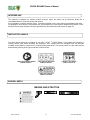
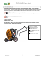
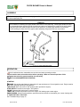
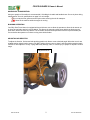
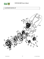
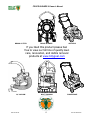
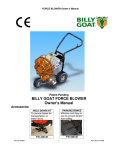
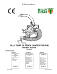
FORCE BLOWER 8 Owner’s Manual
Patent Pending
BILLY GOAT FORCE BLOWER
F800
Owner's Manual
Accessories
HOLD DOWN KIT
PARKING BRAKE
To secure
blower for
transportation
on trailer floors.
Effective and
Easy to use to
prevent blower
from rolling.
P/N 440120
Part No 440187
P/N 440140
FRONT AIR
DIVERTER
AIM AND SHOOT
THROTTLE
CONTROL
Simple to attach,
allowing air to be
directed forward.
Allows up and down
motion via a lever to
easily move debris.
Positions throttle
control at a
convenient
location.
P/N 440188
P/N 440128
P/N 440189
1
Form No F091907C
FORCE BLOWER Owner’s Manual
ABOUT THIS MANUAL
THANK YOU for purchasing a BILLY GOAT ® FORCE Blower. Your new machine has been carefully designed and
manufactured to provide years of reliable and productive service. This manual provides complete operating and
maintenance instructions that will help to maintain your FORCE Blower in top running order. Read this manual
carefully before assembling, operating, or servicing your equipment.
CONTENTS
SERIAL PLATE DATA AND SPECIFICATIONS
3
4-5
GENERAL SAFETY
INSTRUCTION LABELS
6
PACKING CHECKLIST
7
ASSEMBLY
8
OPERATION
9
MAINTENANCE
10
TROUBLESHOOTING AND WARRANTY PROCEDURE
11
ILLUSTRATED PARTS LIST
12
PARTS LIST
13
MAINTENANCE RECORD
14
Part No 440187
2
Form No F091907C
FORCE BLOWER 8 Owner’s Manual
SERIAL PLATE DATA
Record the model number, serial number, date of
purchase, and where purchased.
Purchase Date:
Purchased From:
Specifications
F800
Engine: HP
8 HP (5.96kW)
Engine: Model
202432-0210-E9
Engine: Type
B&S
Engine: Fuel Capacity
4 qt. (3.78L)
Engine: Oil Capacity
28 oz. (0.8L)
Total Unit Weight:
144# (65.3Kg)
Overall Length:
Part No 440187
58"(1.43m)
Overall Width
29.25” (0.74m)
Overall Height
45" (1.14m)
3
Form No F091907C
FORCE BLOWER Owner’s Manual
GENERAL SAFETY INSTRUCTIONS and SYMBOLS
The safety symbols shown below are used throughout this manual. You should become familiar with them before
assembling, operating, or servicing this equipment.
This symbol indicates important information that will prevent injury to yourself or others.
This symbol indicates ear protection is recommended when operating this equipment.
This symbol indicates eye protection is recommended when operating this equipment.
This symbol indicates gloves should be worn when servicing this equipment.
This symbol indicates that this manual and the engine manufacturer’s manual should be read
carefully before assembling, operation, or servicing this equipment.
This symbol indicates important information that will prevent damage to your BILLY GOAT
FORCE Blower.
®
This symbol indicates the engine oil level should be checked before operating this
equipment.
Read and make sure you thoroughly understand the following safety precautions before assembling, operating or
servicing this equipment:
READ this manual and the engine manufacturer’s manual carefully before assembling,
operating, or servicing this equipment.
EAR PROTECTION is recommended when operating this equipment.
EYE PROTECTION is recommended when operating this equipment.
BREATHING PROTECTION is recommended when operating this equipment.
EXHAUST from this product contains chemicals known to the State of California to cause
cancer, birth defects or other reproductive harm.
DO NOT operate this equipment on any unimproved forested, brushy, or grass covered land
unless a spark arrester is installed on the muffler as required by Section 4442 of the
California Public Resources Code. The arrester must be maintained in good working order.
Other states may have similar laws. Federal laws apply on federal lands.
DO NOT run engine in an enclosed area. Exhaust gases contain carbon monoxide, an
odorless and possibly fatal poison.
Part No 440187
4
Form No F091907C
FORCE BLOWER 8 Owner’s Manual
DO NOT run this equipment indoors or in any poorly ventilated area. Refueling outdoors is
recommended.
DO NOT refuel this equipment while the engine is running. Allow engine to cool for at least
two minutes before refueling.
DO NOT store gasoline near an open flame.
DO NOT remove gas cap while engine is running.
DO NOT start or operate engine if strong odor of gasoline is present.
DO NOT start or operate engine if gasoline is spilled. Move equipment away from spill until
gasoline has completely evaporated.
DO NOT smoke while filling the fuel tank.
DO NOT check for spark with spark plug or spark plug wire removed. Use an approved spark
tester.
DO NOT operate engine without a muffler. Inspect muffler periodically and replace if
necessary. If equipped with muffler deflector, inspect deflector periodically and replace if
necessary.
DO NOT operate engine with grass, leaves or other combustible material near the muffler.
DO NOT touch muffler, cylinder, or cooling fins when hot. Contact with hot surfaces may
cause severe burns.
DO NOT leave equipment unattended while in operation.
DO NOT park equipment on a steep grade or slope.
DO NOT operate equipment with bystanders in or near the work area.
DO NOT allow children to operate this equipment.
DO NOT operate equipment with guards removed.
DO NOT operate equipment near hot or burning debris or any toxic or explosive materials.
DO NOT operate equipment on slopes greater than specified in Specifications section of this
manual.
ALWAYS remove spark plug wire when servicing equipment to prevent accidental starting.
ALWAYS check fuel lines and fittings frequently for cracks or leaks. Replace if necessary.
ALWAYS keep hands and feet away from moving or rotating parts.
ALWAYS store fuel in approved safety containers.
WARNING: Important
Do not run this machine without director cone attached or with improper air director cone.
DO NOT run this machine with a cracked or damaged impeller under any circumstances.
Part No 440187
5
Form No F091907C
FORCE BLOWER Owner’s Manual
INTENDED USE
This machine is designed for cleaning outdoor surfaces, where the debris can be effectively blown into a
consolidated area for convenient pickup and removal.
Do not operate if excessive vibration occurs. If excessive vibration occurs, shut engine off immediately and check
for damaged or worn impeller, loose impeller bolt, loose impeller key, loose engine or lodged foreign objects. Note:
See parts list for proper impeller bolt torque specifications. (See trouble shooting section on page 12).
INSTRUCTION LABELS
The labels shown below were installed on your BILLY GOAT ® FORCE Blower. If any labels are damaged or
missing, replace them before operating this equipment. Item numbers from the Illustrated Parts List and part
numbers are provided for convenience in ordering replacement labels. The correct position for each label may be
determined by referring to the Figure and Item numbers shown.
LABEL READ OWNERS MANUAL
ITEM #44 P/N890301
LABEL EAR EYE BREATHING
ITEM# 45 P/N890254
DANGER FLYING DEBRIS
ITEM # 46 P/N 810736
LABEL EXPLOSIVE FUEL
ITEM # 43 P/N 400268
ENGINE LABELS
BRIGGS AND STRATTON
Part No 440187
6
Form No F091907C
FORCE BLOWER 8 Owner’s Manual
PACKING CHECKLIST
These items should be included in your carton. If any of these parts are missing, contact your dealer.
Your BILLY GOAT ® FORCE Blower was shipped in one carton, completely assembled except for the Upper Handle
Assembly and Front Diverter. Mounting hardware for the Upper Handle Assembly can be found in the parts bag.
READ all safety instructions before assembling unit.
TAKE CAUTION when removing the unit from the box the Handle Assembly is attached to the
unit by cables.
PUT OIL IN ENGINE BEFORE STARTING
PARTS BAG &
LITERATURE ASSY
Warranty card P/N- 400972, Owner’s Manual P/N-440187, Handle Hardware-Items #10(washer 8171003),
#11(locknut 8160002), and #36(cap screw 8041032).
Boxing Parts Checklist
Handle Upper Assembly
Item #49 P/N-440185
Parts Bag & Literature Assy
P/N-440186
B & S Intek 8 hp manual
Part No 440187
7
Form No F091907C
FORCE BLOWER Owner’s Manual
ASSEMBLY
1.Follow the steps in figures A then securely tighten all hardware shown.
2.Connect spark plug wire.
Figure A
The hardware for attaching the upper handle to the lower is in the parts bag. Install upper handle (item 49),
to preassembled lower handle (item 28) by sliding the upper over and down the outside of the lower handle.
Using bolt (item #36), washers (item #10) & lock nut (item #11) to install upper handle to lower handle.
Finish installing the other side of the upper handle assembly using screw and lock nut provided.
Two ½” open ended wrenches
OPERATION
Like all mechanical tools, reasonable care must be used when operating machine.
Inspect machine work area and machine before operating. Make sure that all operators of this
equipment are trained in general machine use and safety.
PUT OIL IN ENGINE BEFORE STARTING
STARTING
ENGINE: See engine manufacturer’s instructions for type and amount of oil and gasoline used. Engine must be
level when checking and filling oil and gasoline.
FUEL VALVE: Move fuel valve to "ON" position (when provided on engine).
STOP SWITCH: Located on the engine. "ON" position.
CHOKE: Operated with choke lever on side of engine.
THROTTLE: Controlled by throttle lever on the engine. Pull starting rope to start engine.
ENGINE SPEED: Under normal conditions, operate at minimum throttle to accomplish your current cleaning task.
IF YOUR UNIT FAILS TO START:
See Troubleshooting on page 12.
Part No 440187
8
Form No F091907C
FORCE BLOWER 8 Owner’s Manual
HANDLING & TRANSPORTING:
Using two people to lift machine is recommended. Lift holding the handle and handle brace. Secure in place during
transportation. See unit specifications on page 3 for unit weight.
Do not use the front grill as an anchor point when securing the unit for transport.
Never lift the machine while the engine is running.
BLOWING OPERATION
Your Billy Goat Force blower is equipped with an air director cone to allow the operator to direct the air stream up
or down as required to assist in moving debris. This feature is extremely useful when debris has piled up to the
point that it cannot be blown any farther. The air stream can be directed upward to blow the top of the debris pile
over and allow the operator to continue moving more debris farther.
ADJUSTING AIR DIRECTOR
To adjust air direction, first loosen knob and then position air director cone to desired angle. When the cone is at a
suitable position tighten knob to secure. DO NOT position director cone to where it will blow debris towards people,
vehicles or other objects in vicinity. Flying debris may damage, harm, or cause injury to people or objects in air flow
range.
Adjustment knob
Part No 440187
9
Form No F091907C
FORCE BLOWER Owner’s Manual
MAINTENANCE
PERIODIC MAINTENANCE
Periodic maintenance should be performed at the following intervals:
Maintenance Operation
Inspect for worn or damaged parts.
Every
Use
Daily or Every
5 Hours
Every 25
Hours
Every 50
Hours
Every
100-150
Hours
z
z
Check for excessive vibration
z
Inspect Impeller for cracks or damage
z
Inspect for loose parts.
IMPELLER REMOVAL
1. Wait for engine to cool and disconnect spark plug.
2. Remove housing front cover, by removing (11) bolts and nuts, items #13 & #14, around outside of front
cover.
3. Remove impeller bolt (item #35), lock washer (item #7) and washer (item #34).
4. DO NOT pry on impeller. Pull on center hub area only of impeller. If impeller slides off freely, proceed to
(step 6).
5. If the impeller does not loosen, obtain a 3/4-16x1” (25.4mm) or longer bolt. Thread bolt by hand into nut
until bolt rests against the shaft. Tighten the bolt slowly, which will pull the impeller away from the shaft,
remove impeller from shaft. Using a penetrating oil can help loosen a stuck impeller.
6. Reinstall new impeller in reverse order of removal.
7. Tighten impeller bolt. Torque impeller bolt (see parts list on page 14 for proper impeller bolt torque
specifications).
TIRE AIR PRESSURE
Check at regular intervals and maintain.
Front Tires - 24 Psi (165 kPa).
Rear Tires - 20 Psi (137 kPa).
STORAGE
Never store engine indoors or in enclosed poorly ventilated areas with fuel in tank, where fuel fumes may reach
an open flame, spark or pilot light, as on a furnace, water heater, clothes dryer or other gas appliance.
If engine is to be unused for 30 days or more, prepare as follows:
Remove all gasoline from carburetor and fuel tank to prevent gum deposits from forming on these parts and
causing possible malfunction of engine. Drain fuel outdoors, into an approved container, away from open flame. Be
sure engine is cool. Do not smoke. Run engine until fuel tank is empty and engine runs out of gasoline.
Fuel stabilizer (such as Sta-Bil TM) is an acceptable alternative for minimizing the formation of gum
deposits during storage. Add stabilizer to gasoline in storage container or fuel tank. Follow
stabilizer manufacturer’s instructions to determine proper mix ratio. Run engine at least 10
minutes after adding stabilizer to allow it to reach carburetor.
Part No 440187
10
Form No F091907C
FORCE BLOWER 8 Owner’s Manual
TROUBLESHOOTING
Problem
Abnorm al vibration.
Engine will not start.
Engine is locked, will not pull
over.
Possible Cause
· Loose or out of balance im peller.
Solution
· Check im peller and replace if required.
· Loose engine.
· Check engine.
· Engine not in full choke position.
· Out of gasoline or bad, old gasoline.
· Check choke position.
· Check gasoline.
· Spark Plug wire disconnected.
· Gas valve off.
· Dirty air cleaner.
· Connect spark plug wire.
· Turn on gas valve.
· Clean or replace air cleaner. Contact a
qualified service person.
· Contact an engine servicing dealer for
engine problem s.
· Engine problem .
When servicing engine refer to specific manufacturers engine owner's manual. Engine warranty is covered by the
specific engine manufacturer. If your engine requires warranty or other repair work contact your local servicing
engine dealer. When contacting a dealer for service it is a good idea to have your engine model number available
for reference (See table page 3). If you cannot locate a servicing dealer in your area you can contact the
manufacturers national service organization.
To reach:
Briggs and Stratton: 800-223-3723
WARRANTY CLAIM PROCEDURE
Should a BILLY GOAT ® machine fail due to a defect in material and/or workmanship, the owner should make a
warranty claim as follows:
• The machine must be taken to the dealer from whom it was purchased or to an authorized Servicing BILLY
GOAT Dealer.
•
The owner must present the remaining half of the Warranty Registration Card, or, if this is not available, the
invoice or receipt.
•
The Warranty Claim will be completed by the authorized BILLY GOAT Dealer and submitted to their
respective BILLY GOAT Distributor for their territory Attention: Service Manager. Any parts replaced under
warranty must be tagged and retained for 90 days. The model number and serial number of the unit must
be stated in the Warranty Claim.
•
The distributor service manager will sign off on the claim and submit it to BILLY GOAT for consideration.
•
The Technical Service Department at BILLY GOAT will study the claim and may request parts to be
returned for examination. BILLY GOAT will notify their conclusions to the distributor service manager from
whom the claim was received.
•
The decision by the Technical Service Department at BILLY GOAT to approve or reject a Warranty Claim is
final and binding.
For online product registration go to www.billygoat.com
Part No 440187
11
Form No F091907C
FORCE BLOWER Owner’s Manual
ILLUSTRATED PARTS LIST
Part No 440187
12
Form No F091907C
FORCE BLOWER 8 Owner’s Manual
PARTS LIST
ITEM NO.
1
2
3
4
5
6
7
8
9
10
11
12
13
14
15
16
17
18
19
20
21
22
23
24
25
26
27
28
29
30
31
32
33
34
35
36
37
38
39
40
41
42
43
44
45
46
47
48
49
50
Part No 440187
DESCRIPTION
ENGINE 8 HP B&S
BASE ENGINE WA
SPACER RING ENGINE
PLATE REINFORCE HOUSING
HOUSING FRONT MOLDED
HOUSING BACK MOLDED
WASHER LOCK 3/8 TWISTED TOOTH
WASHER LOCK 7/16 S/T MED
SCREW CAP 3/8-16X1 1/2 ZP
ROD HAND STOP
WASHER 5/16 FLATWASHER Z/P
NYLON INSERT LOCKNUT 5/16-18
SCREWCAP 5/16-18 X 2.5 ZP
SCREWCAP 1/4-20 x 1 1/2
NUT FLANGE 1/4-20
WHEEL & TIRE 13" X 5" PNEUMATIC
RING RETAINING 3/4
SCREW SELF-TAP 5/16 NC X 3/4 HEX
WHEEL ASSY 10 " PNEUMATIC
SPACER FRONT AXLE
SPACER LH WHEEL
SPACER RH WHEEL
SCREWCAP 1/2-13 x 7"
WASHER FLAT 1/2" SAE
WASHER W/BOLT WA
KNOB 3/8-16 SOLID HUB
WASHER 2.25 OD x .515 ID x .134 ZP
ENGINE SPACER
HANDLE LOWER
NYLON INSERT LOCKNUT 1/2-13
SCREWCAP 5/16-18 X 1.75 ZP
F800
PART NUMBER QTY.
440181
1
440011
1
440009
1
440010
2
440023
1
440024
1
400502
4
8177013
1
8041052
4
440057
1
8171003
16
8160002
10
8041034
4
8041008
11
900455
11
440054
2
850230
2
8122082
7
400295
1
440050
1
440052
1
440051
1
8041235
1
8172011
1
440075
1
811230
1
610308-P
1
430355
1
440034
1
8160005
1
8041031
4
NUT LOCK 3/8-16 LT WT THIN ZP
WASHER 1.5 O.D.X 0.45 I.D. X 0.25
SCREWCAP 7/16-20 X 3.5 GR.8 60ft-lbs
8161042
440153
440150
1
2
1
SCREWCAP 5/16"-18 X 2" ZP
DIRECTOR CONE 4"
8041032
440046
-
2
1
-
IMPELLER ASSEMBLY 17"
GRILL FRONT BLOWER
440110
440112
1
1
LABEL HOT ENGINE
LABEL READ
LABEL EAR EYE BREATHING
LABEL DANGER FLYING DEBRIS
GRIP 1-1/4" ID x 13"
LABEL FORCE
HANDLE ASSY UPPER
Key 1/4" SQ x 2.25
400268
890301
890254
810736
440012
440182
440185
9201123
1
1
1
1
2
1
1
1
13
Form No F091907C
FORCE BLOWER Owner’s Manual
MAINTENANCE RECORD
Date
Part No 440187
Service Performed
14
Form No F091907C
FORCE BLOWER 8 Owner’s Manual
BRUSH CUTTER
FORCE BLOWER
AERATOR
If you liked this product please feel
free to view our full line of quality lawn
care, renovation, and debris removal
products at www.billygoat.com
QL VACUUM
Part No 440187
MULTI VACUUM
15
POWER RAKE
Form No F091907C