1
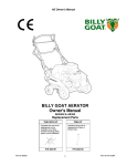
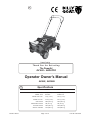
1
R
Patent Pending
T h a n k Yo u f o r S e l e c t i n g
The Powerful
EZ AIR TM AERATOR
Operator Owner's Manual
AE550, AE550H
3
Specifications
ENGINE: H.P.
ENGINE: TYPE
ENGINE: FUEL CAP.
AE550H
5.5 (4.1 kW )
5.5 (4.1 kW )
B&S OHV
HONDA OHV
3.0 qt. (2.84 L)
3.88 qt. (3.41 L)
ENGINE: OIL CAP.
0.66 qt. (0.62 L)
0.69 qt. (0.65 L)
UNIT W EIGHT
290# (131.8 kg)
294# (133.6 kg)
REMOVABLE W EIGHT
Part No. 360178
AE550
36# (16.4 kg)
36# (16.4 kg)
NET UNIT W EIGHT
326# (148.2 kg)
330# (150.0 kg)
W EIGHT: SHIPPING
447# (203.2 kg)
451# (205.0 kg)
Page 1 of 12
Form No. F012302A
5
IN THE INTEREST OF SAFETY
BEFORE STARTING ENGINE, READ AND UNDERSTAND THE “ENTIRE OPERATOR'S MANUAL &
ENGINE MANUAL.”
THIS SYMBOL MEANS WARNING OR CAUTION. DEATH, PERSONAL INJURY AND/OR PROPERTY
DAMAGE MAY OCCUR UNLESS INSTRUCTIONS ARE FOLLOWED CAREFULLY.
WARNING: The Engine Exhaust from this product contains chemicals known
to the State of California to cause cancer, birth defects or other reproductive harm.
WARNING: DO NOT
13. DO NOT tamper with governor springs,
governor links or other parts which may
change the governed engine speed.
1. DO NOT run engine in an enclosed area.
Exhaust gases contain carbon monoxide, an
odorless and deadly poison.
14. DO NOT tamper with the engine speed
selected by the engine manufacturer.
2. DO NOT place hands or feet near moving
or rotating parts.
15. DO NOT check for spark with spark plug
or spark plug wire removed. Use an
approved tester.
3. DO NOT store, spill or use gasoline near
an open flame, or devices such as a stove,
furnace, or water heater which use a pilot
light or devices which can create a spark.
16. DO NOT crank engine with spark plug
removed. If engine is flooded, place throttle
in “FAST” position and crank until engine
starts.
4. DO NOT refuel indoors where area is not
well ventilated. Outdoor refueling is recommended.
17. DO NOT strike flywheel with a hard
object or metal tool as this may cause
flywheel to shatter in operation. Use proper
tools to service engine.
5. DO NOT fill fuel tank while engine is
running. Allow engine to cool for 2 minutes
before refueling. Store fuel in approved
safety containers.
6. DO NOT remove fuel tank cap while
engine is running.
18. DO NOT operate engine without a
muffler. Inspect periodically and replace, if
necessary. If engine is equipped with
muffler deflector, inspect periodically and
replace, if necessary, with correct deflector.
7. DO NOT operate engine when smell of
gasoline is present or other explosive
conditions exist.
19. DO NOT operate engine with an
accumulation of grass, leaves, dirt or other
combustible material in the muffler area.
8. DO NOT operate engine if gasoline is
spilled. Move machine away from the spill
and avoid creating any ignition until the
gasoline has evaporated.
20. DO NOT use this engine on any forest
covered, brush covered, or grass covered
unimproved land unless a spark arrester is
installed on the muffler. The arrester must
be maintained in effective working order by
the operator. In the State of California the
above is required by law (Section 4442 of
the California Public Resources Code).
Other states may have similar laws. Federal
laws apply on federal lands.
9. DO NOT transport unit with fuel in tank.
10. DO NOT smoke when filling fuel tank.
11. DO NOT choke carburetor to stop
engine. Whenever possible, gradually
reduce engine speed before stopping.
12. DO NOT run engine at excessive
speeds. This may result in injury & /or
damage to unit.
6
7
○
○
○
○
○
○
○
○
○
○
○
○
○
○
○
○
○
Part No. 360178
○
○
○
○
WARNING: DO
1. ALWAYS DO remove the wire from the
spark plug when servicing the engine or
equipment TO PREVENT ACCIDENTAL
STARTING.
2. DO keep cylinder fins and governor
parts free of grass and other debris
which can affect engine speed.
3. DO pull starter cord slowly until resistance is felt. Then pull cord rapidly to avoid
kickback and prevent hand or arm injury.
4. DO examine muffler periodically to be
sure it is functioning effectively. A worn or
leaking muffler should be repaired or
replaced as necessary.
5. DO use fresh gasoline. Stale fuel can
gum carburetor and cause leakage.
6. DO check fuel lines and fittings frequently
for cracks or leaks. Replace if necessary
7. Follow engine manufacturer operating
and maintenance instructions.
8. Inspect machine and work area before
starting unit.
SOUND
VIBRATION
8
VIBRATION LEVELS 3.6 g max.
SOUND TESTS
Cloudy
GENERAL CONDITION:
Vibration levels at the operators handles were
measured in the vertical, lateral, and longitudinal
directions using calibrated vibration test equipment.
Tests were performed on 02/06/2002 under the
conditions listed:
Cloudy
GENERAL CONDITION:
○
○
○
25. DO NOT park machine on a steep grade
or slope.
○
○
○
○
23. DO NOT operate during excessive
vibration!
24. DO NOT leave machine unattended
while in operation.
○
○
○
○
○
○
○
○
○
○
○
○
○
22. DO NOT run engine without air cleaner
or air cleaner cover.
Sound tests conducted were in accordance
with 2000/14/EEC and were performed on
02/05/2002 under the conditions listed:
TABLE OF CONTENTS
SAFETY INSTRUCTIONS
2
3
GENERAL SAFETY
3
ASSEMBLY
4
CONTROLS
LABELS
4
OPERATION
6-7
10-11
MAINTENANCE
PARTS DRAWING & LIST... 8 - 9
TROUBLESHOOTING
12
WARRANTY PROCEDURE
12
21. DO NOT touch hot muffler, cylinder, or
fins because contact may cause burns.
○
○
101 dB
TEMPERATURE:
42 F
(6 C)
3.5 MPH (5.6 kmh)
TEMPERATURE:
37 F
WIND SPEED:
5 MPH (8 kmh)
(3 C)
○
○
○
○
○
WIND DIRECTION:
North East
WIND DIRECTION:
North East
HUMIDITY:
53 %
HUMIDITY:
90 %
BAROMETRIC PRESSURE: 30.29" Hg (769 mm Hg) BAROMETRIC PRESSURE:30.13" Hg (765 mm Hg)
Page 2 of 12
Form No. F012302A
GENERAL SAFETY
9
For your safety and the safety of others, these directions should be followed:
Do not operate this machine without first reading
owner's manual and engine manufacturer's manual.
Use of Ear Protection is recommended while
operating this machine.
Use of Eye and Breathing protection is recommended
when using this machine, especially in dry and dusty
conditions.
Wearing gloves is recommended while
operating this machine.
·DO NOT place hands or feet underneath unit, near debris
outlet or near any moving parts.
·DO NOT start engine without tine height adjust lever in up
position and clutch bail disengaged.
·DO NOT start or operate machine with guards removed.
·DO NOT perform any service on the unit without removing
the spark plug wire.
10
-DO read all maintenance and operating instructions before
begining work.
-DO read all engine manufacturers operating and maintenance
instructions.
-DO inspect lawn before begining work. Remove all rocks, wire,
string, or other objects that can present a hazard during work prior to
starting.
-DO identify and mark all fixed objects to be avoided during work,
such as sprinkler heads, water valves, buried cables, or clothes line
anchors, etc.
ASSEMBLY
Read all safety and operating instructions
before assembling or starting this unit.
PUT OIL IN ENGINE BEFORE STARTING
Your Billy Goat EZ-Air aerator is shipped from the factory in one
carton, completely assembled.
1. REMOVE lock nuts from the upper handle mounting stud. These
will be reused.
2. UNFOLD the upper handle and pivot it back into the operating
position. NOTE: There are two height positions that the handle can
be set in. The lower stud places the handle in the highest position
the upper stud places the handle in the lowest operating position.
11
·DO NOT operate a machine that exhibits excessive vibration.
·DO NOT operate this machine on slopes greater than 19°.
·DO NOT use this unit on any surface other than grass lawns.
·DO NOT allow children to operate this equipment.
3. SECURE the upper handle by positioning the lowermost mounting hole
over the chosen handle mounting stud and tightening the hand knob on
the handle pivot bolt to secure the handle in position.
4. REPLACE the lock nuts that were removed in step one and fully
tighten them to complete securing the handle in place.
5. ATTACH the lift rods, one on each side of the unit. Remove the hair
pins that are shipped in free end of the rods. Pivot the rods up and along
the side of the unit and slip the free end of the rod into the lift link bars
one on each side of the unit. With the rods in position, replace the hair
pins in the holes that they were removed from to lock the lift rods in
place.
5. CHECK engine oil level and fill to proper level. See engine owners
manual for type and amount of oil to use. Move the tine height adjust
lever to the down position, to level engine during checking.
6. CONNECT spark plug wire. HONDA ONLY: Set the engine stop switch
to the on position. You will use the stop switch on the handle during
operation.
PACKING CHECKLIST
These items should be included in your carton. If any
of these parts are missing, contact your dealer.
Per Model
Check
Engine
Manual Per
Model
Briggs & Stratton
5.5 Intek OHV
Check
Honda 5.5 OHV
Check
Owner's
Manual
360178
Literature
Assembly
360177
Check
Warranty
Card 400972
Check
Part No. 360178
Page 3 of 12
EU Declaration
of Conformity &
EU Distributor
List 360194
Form No. F012302A
CONTROLS
13
HONDA ENGINE THROTTLE CONTROL
B & S ENGINE THROTTLE CONTROL
Set lever to choke position when
starting a cold engine
THROTTLE LEVER
RUN
CHOKE
STOP
Set lever to desired engine speed.
Move lever completely to the left
to stop engine
ENGINE LABELS
15
FUEL VALVE
CHOKE LEVER
Briggs & Stratton
ON
14
RUN
CHOKE
INSTRUCTION LABELS
OFF
These labels should be included on your Aerator. If any of
these labels are damaged, replace them before putting this
equipment into operation. Item and part numbers are given to
help in ordering replacement labels.
EXPLOSIVE FUEL
STOP ENGINE AND ALLOW T O
COOL BEFORE REFUELING.
400268
WARNING
Label Danger
Keep Hands
and Feet Away
Part No.400424
..
Label Do Not Fill While
Engine Is Hot
Part No.400268
THIS ENGINE EQUIPPED WITH
LOW OIL SENSOR, IF ENGINE WILL
NOT START, CHECK OIL LEVEL
'
'
'
WARNING
Read and follow Operating
Instructions before running engine.
Gasoline is flammable. Allow engine
to cool at least 2 minutes before fueling.
Engines emit carbon monoxide,
DO NOT run in enclosed area.
WARNING
LIFT HERE
Honda
THE UNIT WEIGHS OVER 300 LBS.
LIFT HERE WITH CAUTION
Label Warning Unit Weight
Part No.360188
Label LIFT HERE ARE
Part No.360187
WARNING
900327
Label Danger Guard
Part No.900327
OPERATING INSTRUCTIONS
BEFORE STARTING, MAKE SURE:
TO START, MOVE ENGINE STOP SWITCH TO "ON" AND PULL ROPE.
NOTE: IT MAY BE NECESSARY TO USE THE ENGINE CHOKE IF
TINE DEPTH CONTROL BAIL IS IN UP POSITION.
ALL GUARDS ARE ATTACHED.
ENGINE IS COLD.
PUSH FORWARD ON TINE LIFT HANDLE TO ENGAGE TINES
IN GROUND.
PUSH FORWARD ON OPERATOR'S BAIL TO ENGAGE DRIVE AND
START AERATING.
DURING OPERATION PUSHING DOWN ON OPERATOR'S HANDLE
WILL MAXIMIZE CORING DEPTH.
RELEASE BAIL TO STOP UNIT.
NOTE: ENGINE WILL CONTINUE TO RUN WITH BAIL DISENGAGED.
TO TURN UNIT, PULL BACK ON TINE LIFT HANDLE TO LIFT TINES
OUT OF GROUND. GRADUAL TURNS CAN BE MADE WITHOUT
LIFTING THE TINES.
WITH TINES UP, PUSH FORWARD ON OPERATOR'S BAIL TO
ENGAGE WHEELDRIVE FOR ASSISTED TURNING.
TO STOP ENGINE MOVE ENGINE STOP SWITCH TO "OFF".
OIL ALERT
FOR PREVENTATIVE MAINTENANCE
READ OWNERS MANUAL
BEFORE OPERATING
CHECK ENGINE OIL DAILY.
INSPECT AND CLEAN ENGINE AIR FILTER DAILY.
REPLACE AS NEEDED.
GREASE ALL BEARINGS AND CHECK GEAR REDUCTION
OIL LEVEL ON EVERY ENGINE OIL CHANGE.
ALWAYS:
USE PERSONAL
PROTECTION EQUIPMENT
INSPECT MACHINE BEFORE EACH USE AND REPLACE ANY
WORN AND DAMAGED PARTS.
PROPERLY SECURE EQUIPMENT BEFORE TRANSPORTING.
DISCONNECT SPARK PLUG WIRE BEFORE SERVICING UNIT.
USE ONLY A QUALIFIED MECHANIC T O SERVICE THIS MACHINE.
WHEN OIL LEVEL LOW,
ENGINE STOPS IMMEDIATELY.
360191
Label Instructions Height Adjust - Part No. 350224
Part No. 360178
Page 4 of 12
Form No. F012302A
16
Operation
INTENDED USE: This machine is designed for aerating
established lawns and large grass covered areas. The
machine should not be used for any other purpose than
that stated above.
TINES RAISING/LOWERING
DO NOT operate if excessive vibration occurs. If excessive
vibration occurs, shut engine off immediately and check for
damaged or worn tine reel, loose pulley bolts or set screws,
loose engine or lodged foreign objects. (See trouble
shooting section on page 12).
The tines are raised or lowered into the ground by operating
the tine engagement lever on the upper handle. Tine
penetration is very dependent on surface preparation. READ
the operation section before aerating.
TINES UP
TRANSPORT
Like all mechanical tools, reasonable care must
be used when operating machine.
Inspect machine work area and machine before operating. Make sure that all operators of this equipment are
trained in general machine use and safety.
STARTING ENGINE
ENGINE: See engine manufacturer’s instructions
for type and amount of oil and gasoline used.
Engine must be level when checking and filling oil and
gasoline.
TINES DOWN
RUNNING
GEAR REDUCTION: See engine manufacturer’s instructions for type and amount of oil used. Engine must be level
when checking and filling the gear reduction case. The
engine is shipped from the factory with oil in the gear case.
It shoudl be checked before first use.
ENGINE SPEED: Controlled by throttle lever on the upper
handle. Under normal conditions, operate at the minimum
throttle speed to accomplish your task.
NOTE: The unit ground speed varies with the engine speed.
FUEL VALVE: Move fuel valve to "ON" position
Honda: Located below the air cleaner on the engine.
Briggs: Located on face of the engine.
ENGINE STOP SWITCH: Move to "ON" position
Honda only: Located on side of engine. During normal
operation use the remote stop switch on the operators
handle.
CHOKE: Engage the choke when starting a cold engine.
Honda: Located below the air cleaner on the engine.
Briggs: Located on top of the air cleaner on the engine.
THROTTLE: Move the throttle control on the upper handle
to fast position. Pull starting rope to start engine.
IF YOUR UNIT FAILS TO START:
See Troubleshooting on page 12.
NOTE: Honda engines are equiped with a low oil sensor to
prevent engine damage. When it senses a low oil condition
(i.e. unit is operating or sitting on a steep slope) the engine
shuts down. The low oil condition must be corrected before
the engine can be restarted. See the engine owners
manual for more information.
Part No. 360178
AERATING OPERATION
DO NOT- Use this machine on any surface other than a lawn or
similar area.
DO NOT- Use this machine on slopes in excess of 19°.
DO NOT- Allow persons unfamiliar with this equipment to operate it.
DO NOT- Allow children to operate this equipment.
MOW: Mow the lawn to it's normal cut height.
WATER: For the best performance and maximum tine
penetration the lawn should be thoroughly watered the day
before aeration.
INSPECT lawn before begining work. Remove all rocks, wire,
string, or other objects that can present a hazard during work
prior to starting.
IDENTIFY and mark all fixed objects to be avoided during
work, such as sprinkler heads, water valves, buried cables, or
clothes line anchors, etc.
START ENGINE: See above.
SET SPEED: The ground speed of your aerator varies with
the engine speed. Set the engine at approximately half
throttle to start. Speed may be increased based on the turf
conditions (i.e. large flat areas) and operator experience.
Speed should be lowered when operating under adverse turf
conditions (i.e. fenced areas, hills, or slopes).
MOVE: Be sure the tine engagement control is in the up
position (tines out of the ground) and engage the wheel drive
by squeezing the operators clutch bail against the handle.
Transport the aerator to the work area.
Page 5 of 12
Form No. F012302A
16
OPERATION
continued
AERATOR OPERATION CON'T
Hints!
ENGAGE TINES: With the aerator in the work area, release
the clutch bail and push forward on the tine engagement
lever, lowering the tines into the dirt.
AERATE: Engage the operators clutch bail by pushing it
forward to the handle, and start aerating.
NOTE: For maximum tine penetration apply downward
pressure on the handle.
TURNING: At the end of an aerating run, release the clutch
bail and pull back on the tine engagement control to lift the
tines out of the ground. Using the handle swivel the rear of
the unit to bring it around and line up for the next pass.
NOTE: Engage the clutch bail to use the front wheel drive to
aid in turning the unit.
TRANSPORT: Be sure to lift the tine engagement lever (tine
out of the ground) before transporting away from the work
area.
HANDLING & TRANSPORTING
CAUTION: This unit is heavy. It requires at least two people to lift it.
REMOVE: The aerator is equiped with a removable rear weight.
Remove the weight when loading and unloading the unit. The weight
can be removed by rotating the locking tabs on the weight mounting
pins and lifting it straight up. See Fig. 1 below.
NOTE: The removable weight is also heavy and should handled
carefully and secured in place during transport.
AERATING TIPS
WATER: For the best performance and maximum tine
penetration the lawn should be thoroughly watered the day
before aeration.
SLOPES: Do not operate the aerator on steep slopes. Use
extreme caution when operating on any sloped surface.
For lesser sloped areas operate the unit, traversing up and
down at a 45 degree angle to the slope rather than straight
across. Extended operation on steep slopes can cause
engine damage.
NOTE: DO NOT release the operators clutch bail when
operating on a slope. This will allow the unit to free wheel
and allow the unit to roll down the slope.
NOTE: Honda engines are equiped with a low oil sensor to
prevent engine damage. When it senses a low oil condition
(i.e. unit is operating or sitting on a steep slope) the engine
shuts down. The low oil condition must be corrected before
the engine can be restarted. See the engine owners
manual for more information.
TINE PENETRATION: Maximum tine penetration is
achieved by applying downward pressure on the handle
during operation.
TURNING: At the end of a pass the tines can be lifted out of
the ground to turn by lifting straight up on the operators
handle.
LIFTING: The aerator is equiped with lift handles. After removing the
weight lift the unit with two people one on each side of the unit. Grip
the unit at the points marked "LIFT HERE" when lifting. Lift using
your legs and not your back. See Fig. 2
USING RAMPS: Use ramps that are of adequate strength for a unit
of this weight. When loading the aerator using ramps be sure the
ramp is not too steep and that the surface of the ramp provides good
traction.
Fig. 1
Fig. 2
Part No. 360178
Page 6 of 12
Form No. F012302A
16
OPERATION
continued
ADJUSTING HANDLE HEIGHT
UNIT STORAGE
This unit is equipped with a height adjustable upper handle to allow
for multiple operator heights.
TO ADJUST THE HANDLE HEIGHT:
1. Remove the lock nuts (item 50) that secure the handle, one on
each side, to the lower handle mounting studs. See Fig. 1
2. Loosen the handle mounting knobs (item 51), one on each side,
(See Fig. 3) and push the handle out and away from the lower
handle mounting studs.
3. The handle is now free to rotate. Adjust the handle to the
desired height. The BOTTOM handle mounting stud coresponds
with the highest handle position. The TOP handle mounting stud
coresponds with the lowest handle mounting position.
4. Completely tighten the handle mounting knobs (item 51), and
replace the lock nuts (item 50) to secure the handle in place.
Never store engine indoors or in enclosed poorly ventilated areas
with fuel in tank, where fuel fumes may reach an open flame, spark or
pilot light, as on a furnace, water heater, clothes dryer or other gas
appliance.
If engine is to be unused for 30 days or more, prepare as follows:
Remove all gasoline from carburetor and fuel tank to prevent
gum deposits from forming on these parts and causing possible
malfunction of engine. Drain fuel outdoors, into an approved
container, away from open flame. Be sure engine is cool. Do not
smoke. Run engine until fuel tank is empty and engine runs out of
gasoline.
NOTE: Fuel stabilizer (such as Sta-Bil) is an acceptable alternative in minimizing
the formation of fuel gum deposits during storage. Add stabilizer to gasoline in
fuel tank or storage container. Always follow mix ratio found on stabilizer
container. Run engine at least 10 min. after adding stabilizer to allow it to reach
the carburetor.
FOLDING HANDLE
PARKING
This unit is equipped with a folding upper handle for easier storage.
TO FOLD THE HANDLE:
1. Remove the lock nuts that secure the handle, one on each side,
to the lower handle mounting studs. See Fig. 1
2. Remove the hair pins that secure the tine lift rods, one on each
side, to the tine lift links. See Fig. 2
3. Slide the rods out of the lift links and replace the pins in the holes
they were removed from for storage.
4. Rotate the lift rods down and back until they and hanging down
and to the rear of the unit.
5. Loosen the handle mounting knobs, one on each side, (Fig. 3)
and push the handle out and away from the lower handle mounting
studs.
6. The handle is now free to rotate. Rotate it up and toward the
front of the unit while holding the tine engagement control lever
against the rear of the upper handle. The handle will rotate into a
position with the top of the handle hooking over the front bumper of
the unit.
NOTE: Replace the lock nuts (item 50) on the lower handle
mounting studs for storage.
NEVER PARK THIS UNIT ON A SLOPE OF ANY KIND.
Always keep tines in the up position when parking the unit.
Fig. 2
Fig. 1
Fig. 3
Part No. 360178
Page 7 of 12
Form No. F012302A
AE550, AE550H
PARTS DRAWING
R
18
Part No. 360178
Page 8 of 12
Form No. F012302A
Part No. 360178
Page 9 of 12
Form No. F012302A
KEY SQUARE 3/16 x 3/16 x 1.25
7
8
360111
8041051
1
12
HANDLE LIFT LH WA
LINK LIFT LOWER
LINK LIFT UPPER
WASHER FLAT 3/8 SAE
SCREWCAP 3/8 -16 x1
SPRING EXTENSION
ROD LIFT
PIN HAIR 1/4
HANDLE
FLAT WASHER 1/2
NUT LOCK 5/16 -18
41
42
43
44
45
46
47
48
49
50
37
40
BUSHING PIVOT
36
BOLT CARRIAGE 3/8-16 x 1.25"
NUT LOCK 5/8-11 THIN
35
HANDLE LIFT RH WA
BOLT SHOULDER 3/4 x 2.5
34
39
BUMPER
33
38
SPACER SPROCKET IDLER 1.3"
SCREW CAP 1/2 - 13 x 2.5"
32
SPACER SPROCKET IDLER 2.5"
SPROCKET IDLER 17T x 5/8" BORE
29
SCREW CAP 1/2 - 13 x 4
BOLT SHOULDER 1/2 x 1
28
31
SCREWCAP 3/8-16 x 1 1/2
27
30
ROD FINGER BELT
CHAIN #40 x 76 PIT CH O-RING (TINE)
22
BRACKET MOUNT IDLER
CHAIN #40 x 94 PIT CH O-RING (WHEEL)
21
26
BELT 4L x 43" POWER RATED
20
25
SPOCKET 16T x 1" BORE
19
PULLEY IDLER 4.5"
PULLEY 8" x 1" BORE
18
ARM IDLER WA
KEY SQUARE 1/4 x 1/4 x 6"
17
24
NUT LOCK 3/8-16
16
23
JACKSHAFT AERATOR
SCREW SELF TAP 1/4 x 3/4"
13
BEARING 1" PILLOW BLOCK
GUARD DIF FERENTIAL AE
12
15
SCREWCAP 5/16-18 x 1"
11
14
WASHER 5/16 FENDER
WASHER LOCK 5/16 TWISTED TOOTH
9
10
8160002
8171006
360165
900471
360166
360154
8041050
8172009
360150
360151
360149
360148
8024059
360183
8161046
360146
360139
8041100
360124
8041106
360123
360116
500114
8041052
360185
360121
510199
500270
360114
360115
360120
360113
360118
9201143
8160003
810700
360110
510208
360196
8041028
8181008
83
2
1
4
2
2
8
24
2
2
1
1
4
4
2
2
1
1
1
1
1
2
1
1
1
1
1
1
1
1
1
2
1
1
26
2
1
12
1
4
2
4
8172020
DIFFERENTIAL 35T AERATOR
6
1
4
2
SCREWCAP 3/8-16 x 1 1/4
5
360125
350133
360157
BEARING 3/4" PILLOW BLOCK
4
1
WHEEL 10.5" SEMI PN. W3/4" KEYED HUB
GUARD DRIVE COVER
3
360160
1
QTY
3
GUARD TINE COVER
2
Part No.
360130
AE550H
9201080
FRAME ASSEMBLY
DESCRIPTION
1
IT EM
NO.
AE550
8160002
8171006
360165
900471
360166
360154
8041050
8172009
360150
360151
360149
360148
8024059
360183
8161046
360146
360139
8041100
360124
8041106
360123
360116
500114
8041052
360185
360121
510199
500270
360114
360115
360120
360113
360118
9201143
8160003
810700
360110
510208
360196
8041028
8181008
8172020
360157
9201080
360111
8041051
350133
360160
Part No.
360130
83
2
1
4
2
2
8
24
2
2
1
1
4
4
2
2
1
1
1
1
1
2
1
1
1
1
1
1
1
1
1
2
1
1
26
2
1
12
1
4
2
4
2
3
1
12
4
1
1
1
QTY
WASHER RUBBER 5/8 x 1.5
ENGINE 5.5 HP
PULLEY ENGINE
57
58
59
60
BOLT CARRIAGE 5/16 -18 x 1.75"
72
BOLT CARRAIGE 1/4-20 x 1 3/4
SPACER WASHER NYLON
89
90
101
SWITCH ON-OFF
HARNESS WIRE AE
BRACKET MOUNT SWITCH
100
102
NUT LOCK 1/4x 20
SCREW CAP 1/4 - 20 x2"
99
BUSHING SHOULDER NYLON 3/8 ID
97
98
BOLT CARRIAGE 5/16 -18 x 3.5"
BOLT SHOULDER 3/8 x 2"
BOLT SHOULDER 3/8 X 1"
BOLT SHOULDER 3/8 x 3/4"
BOLT SHOULDER 3/8 x 1/2"
96
95
94
93
92
TIRE & WHEEL 8"
RIG CASTER w/AXLE, NUT & BUSHING
88
91
CLAMP HANDLE NYLON
PIN MOUNT BAR
83
SPACER
82
NUT LOCK 1/2 -13
81
WASHER 1/4 FLAT CUT
WASHER FLAT CUT 5/16
SCREW CAP 5/16 - 18 x 1.5"
80
77
76
75
74
SHAFT TINE DRIVE
NUT JAM 7/8 -14
71
73
WASHER
TY-WRAP
68
WASHER LOCK 7/8" INTERNAL
SPACER
67
70
SPACER
69
TINE
66
TINE PLATE
CAP SCREW 5/16-18 x 1.75"
SPACER
65
64
63
62
SPROCKET 42 T
WEIGHT
56
61
CABLE CLUTCH ASSY
CABLE THROTTLE W/LEVER
55
BOLT SHOULDER 3/8 X 1
BAIL CLUTCH
54
HANDLE LIFT
KNOB HANDLE
DESCRIPTION
53
52
51
NO.
ITEM
AE550H
500311
430141
360199
8041010
8160001
360175
8024050
360153
360152
360184
830528
360156
800109
8024025
360155
360161
360186
360109
8161044
8171002
8171003
8041030
360102
8024043
350155
350154
350153
900407
360104
360105
360100
360101
8041031
360107
360106
360117
360126
430210
360162
360170
360119
360168
360152
360167
400339
Part No.
1
1
1
1
2
8
2
2
2
2
4
2
8
1
2
2
2
1
2
2
6
4
1
60
1
1
1
3
4
6
30
10
3
3
1
1
1
2
1
1
1
1
2
1
2
QTY
AE550
500311
430141
360199
8041010
8160001
360175
8024050
360153
360152
360184
830528
360156
800109
8024025
360155
360161
360186
360109
8161044
8171002
817003
8041030
360102
8024043
350155
350154
350153
900407
360104
360105
360100
360101
8041031
360107
360106
360117
360127
430210
360162
360170
360119
360168
360152
360167
400339
Part No.
1
1
1
1
2
8
2
2
2
2
4
2
8
1
2
2
2
1
2
2
6
4
1
60
1
1
1
3
4
6
30
10
3
3
1
1
1
2
1
1
1
1
2
1
2
QTY
17
MAINTENANCE
Use only a qualified mechanic for
any adjustments, disassembly or
any kind of repair .
WARNING: TO AVOID PERSONAL INJURY, ALWAYS
TURN MACHINE OFF, MAKE SURE ALL MOVING
PARTS COME TO A COMPLETE STOP.
DISCONNECT SPARK PLUG WIRE
BEFORE SERVICING UNIT.
ENGINE: See engine manufacturer's
service instructions.
REPLACE ALL GUARDS, BEFORE
STARTING ENGINE.
USE ONLY BILLY GOAT ORIGINAL
EQUIPMENT PARTS FOR
REPLACEMENT AND REPAIR
TINE ROW KIT 360197
Complete tine row set for
replacement of one
complete row of tines.
Includes mounting
plates, spacer, and all
hardware.
TINE REEL REMOVAL AND TINE ROW REPLACEMENT
TINE REEL REMOVAL
NOTE: Tine reel removal is only necessary to replace an entire
tine row or for other major unit maintenance. Individual tines
can be replaced by following the TINE REPLACEMENT instructions.
1. Wait for engine to cool and disconnect spark plug.
2. Remove the top guard by removing the four screws, two on each
side, that secure it to the frame.
3. Release the tension on the chain. See CHAIN TENSION ADJUSTMENT in this manual.
4. Remove the four bolts and nuts, two on each side, holding the tine
reel bearings in place. BE CAREFUL the tine reel is heavy and
sharp. Take precautions to not allow it to fall when the bearing bolts
are removed.
5. Lift the reel up and to the side to remove it from the drive chain.
6. See TINE ROW REPLACEMENT for instructions on maintenance.
7. To reinstall the reel follow the above steps in reverse.
8. Replace the guard and reinstall the four screws that secure it in
place.
TINE ROW REPLACEMENT
1. Wait for engine to cool and disconnect spark plug.
2. Remove the top guard by removing the four screws, two on each
side, that secure it to the frame.
3. Remove the tine reel per the TINE REEL REMOVAL instructions.
4. Remove the nut at the end of the tine reel shaft that secures the
tine rows in place.
5. Remove the tine rows and spacers as necessary to replace the
defective part. Be sure to note the order in which the spacers were
removed for later reassembly.
6. Reassemble the tine reel in the exact order that it was disassembled.
7. Tighten the nut that secures the tine rows and spacers on the
shaft. Torque the nut to a minimum of 60 ft.lbs. Check that all of the
tine rows are tight by attempting to move them by hand.
8. Reinstall the tine reel per the TINE REEL REMOVAL instructions
above.
9. Re set the tension on the chain.
10. Replace the guard and reinstall the four screws that secure it in
place.
REPLACING INDIVIDUAL TINES
TINE KIT 360100
1. Wait for engine to cool and disconnect spark plug.
2. Loosen but do not remove the outermost nut and carraige bolt that
secure the damaged or worn tine.
3. Loosen and remove the innermost nut and carraige bolt that hold
the tine in the reel.
4. Use a small prybar and push the tine plates apart slightly to slide
out the tine to be replaced.
5. Slide the new tine in place and secure with the innermost nut and
carraige bolt. Tighten completely.
6. Retighten the outermost nut and carraige bolt to completely secure
the new tine.
7. Repeat as required to replace all damaged or worn tines.
Individual coring tine for
replacement of worn or
broken tines.
Tip!!!
NOTE: Tines are a normal wear item and should be inspected
regularly for signs of wear or damage.
Spraying tines with a rust preventing lubricant can
increase tine life and allow for easier replacement of worn
or damaged tines.
Part No. 360178
Page 10 of 12
Form No. F012302A
17
MAINTENANCE
BELT AND CHAIN TENSION ADJUSTMENT
DRIVE BELT REPLACEMENT
ADJUSTING BELT TENSION1. Remove the top guard (item 3) by removing the four screws (item
13), two on each side, that secure it to the frame.
2. Locate the top of the belt idler assembly where the clutch cable (item
55) is secured in place. A properly tensioned belt should stretch the
idler spring (loacted next to the idler pulley) between 1/4" - 3/8" when
the clutch bail (item 54) is held in the drive position.
3. Using a 1/2" wrench loosen the two nuts that secure the cable (item
55) in place.
4. TO INCREASE belt tension adjust these two nuts so that the cable
(item 55) is secured in place with an additional 1/4" of the threaded
adjuster at the top of the assembly.
TO DECREASE belt tension adjust these two nuts so that the cable
(item 55) is secured in place with 1/4" less of the threaded adjuster at
the top of the assembly.
5. Replace the guard (item 3) and reinstall the four screws (item 13) that
secure it in place.
6. Run the unit to test your adjustment. Repeat as necessary to
achieve proper adjustment. A properly adjusted belt will pull the unit up
a 15 degree slope when clutched without any belt slip, and will declutch
and stop the unit completely when the clutch is released.
1. Wait for engine to cool and disconnect spark plug.
2. Remove the top guard by removing the four screws, two on each
side, that secure it to the frame.
3. Slide the belt off of the engine drive pulley, and off of the jackshaft
drive pulley.
4. Continue sliding the belt along the jackshaft to the right jackshaft
bearing away from the pulley and sprockets.
5. Using a 9/16" wrench, remove the two bolts and nuts that hold the
jackshaft bearing in place.
6. Carefully lift the jackshaft up until the belt can be slid out underneath
the bearing.
7. Slide the new belt in place over the jackshaft.
8. Replace and tighten the bolts and nuts holding the jackshaft bearing
in place. Be sure that the jackshaft is aligned straight across between
both bearings.
9. Slide the belt along the jackshaft and over both engine and jackshaft
pulleys. Be sure the idler pulley is positioned on the flat side of the belt.
10. Check proper belt tension. See BELT TENSION ADJUSTMENT in
this manual.
CHAIN REPLACEMENT
NOTE: Never release the clutch on a slope. The unit is heavy and will
free wheel down hill.
NOTE: A worn belt will not allow for proper adjustment and must be
replaced.
ADJUSTING CHAIN TENSION1. Remove the top guard (item 3) by removing the four screws (item
13), two on each side, that secure it to the frame.
2. Locate the bolt (item 31, 33) and nut (item 80) that hold each idler
sprocket to the frame of the unit. One idler sprocket sets tension on the
wheel drive chain and one sets tension on the tine drive chain.
3. Loosen the bolt and nut and slide the idler sprocket (item 29) in the
desired direction.
INCREASED TENSION: Slide the sprocket to the rear.
DECREASED TENSION: Slide the idler sprocket to the front.
4. Tighten the bolt and nut to secure the sprocket in place.
5. Replace the guard and reinstall the four screws that secure it in
place.
NOTE: Over tensioning the chain will cause premature chain and
sprocket wear. DO NOT OVER TENSION THE CHAIN. A properly
tensioned chain will have slack of 1/4"-3/8" when moved by hand.
NOTE: This procedure will work to change the wheel drive chain
or the tine drive chain.
1. Wait for engine to cool and disconnect spark plug.
2. Remove the top guard by removing the four screws, two on each
side, that secure it to the frame.
3. Roll the unit until the master link of the chain that you want to repalce
is exposed near the jackshaft sprocket.
4. Release the tension on the chain. See CHAIN TENSION ADJUSTMENT in this manual.
5. Using a screwdriver or similar device remove the spring clip that
secures the master link in the chain.
6. With the master link removed unwind the chain from the two sprockets that it connects.
7. Carefully string the replacement chain around the same two sprockets and reconnect it with the new master link provided with your
replacement chain.
8. Re set the tension on the chain.
9. Replace the guard and reinstall the four screws that secure it in
place.
Maintenance Schedule
Maintenance Operation
Follow these hourly
maintenance intervals.
Every Use
(Daily)
Every
25 hrs
Engine (See Engine Manual)
Check engine oil
Check gear reduction oil level
Grease bearings (See Lubrication)
Oil chains (See Lubrication)
Inspect for loose, worn,
or damaged parts
Throughly clean all debris from unit
and tine reel.
Inspect belt
Lubricate caster rigs
Part No. 360178
Page 11 of 12
Form No. F012302A
20
TROUBLESHOOTING
Before Requesting Service Review These Suggestions
Solution
Possible Cause
Problem
Engine stalls or labors when raking.
Working on too steep a slope.
Work at 45 degrees to the slop moving up and down
instead of across.
Abnormal vibration.
Damaged or missing tines. Loose handle bolts. Loose
engine bolts
Stop work immediately. Replace any damaged or
missing tines. Tighten all loose bolts and nuts.
Engine will not start.
Stop switch off (Honda only). Throttle in off position.
Engine not in full choke position. Out of gasoline. Bad
or old gasoline. Spark Plug wire disconnected. Dirty air
cleaner. Engine oil level too low (Honda only).
Check stop switches, throttle, choke position and
gasoline. Connect spark plug wire. Clean or replace
air cleaner. Check and fill engine oil. Contact a
qualified service person.
Engine is locked, will not
pull over.
Debris locked against reel, or drive pulleys. Engine
problem.
Pull spark plug wire and remove debris. Contact an
engine servicing dealer for engine problems.
Engine is making loud noise or squealing.
Gear reduction oil level is low.
Check and add oil according to engine owners manual.
Unit does not move when
clutch is engaged.
Belt drive out of adjustment. Work drive belt.
Loose or damaged chain or sprockets. Loose or
damaged pulleys. Damaged or broken clutch cable.
See maintenance on page 7 of this manual. Contact a
qualified servicing dealer.
ENGINE
LUBRICATION
ENGINE
HORSEPOWER
MODEL NO.
GOVERNED RPM
BRIGGS &
STRATTON
5.5
127452-0049-E1
3600
HONDA
5.5
GX160K1HX2
3600
When servicing the engine refer to specific manufacturers engine
owner's manual. All engine warranty is covered by the specific engine
manufacturer. If your engine requires warranty or other repair work
contact your local servicing engine dealer. When contacting a dealer
for service it is a good idea to have your engine model number
available for reference(See table page above). If you can not locate a
servicing dealer in your area you can contact the manufacturers
national service organization.
To contact:
Briggs & Stratton: 800-233-3723
American Honda: 800-426-7701
Engine Service and Warranty
22.1
21
22
Contact your nearest engine manufacturer's
authorized servicing dealer. (See above)
Serial Plate
BEARINGS1. Remove the top guard by removing the four screws, two on each
side, that secure it to the frame. NOTE: Guard must be removed to
lubricate the jackshaft bearings only. All other bearings can be lubed
without removing the guard.
2. Lubricate all 6 bearings using a pressurized grease gun with a
standard lithium based grease.
3. Wipe any excess grease off of all bearings and fittings after each
lubrication.
4. Replace the guard and reinstall the four screws that secure it in
place.
CHAINS1. Remove the top guard by removing the four screws, two on each
side, that secure it to the frame.
2. Apply a light coat of No. 30 Oil or a penetraing chain lubricant to keep
the chain clean and in good running order.
3. Replace the guard and reinstall the four screws that secure it in
place.
CASTERS1. Lubricate both caster rig bearings using a pressurized grease gun
with a standard lithium based grease.
2. Wipe any excess grease off of all bearings and fittings after each
lubrication.
Record your machine model, serial number and
date-of-purchase and where purchased
WARRANTY PROCEDURE
Please fill in the WARRANTY CARD and send the upper part to Billy Goat.
The WARRANTY terms are stated on the lower part which remains with the
user. Whenever a Billy Goat Machine is faulty due to a defect in material
and / or workmanship, the owner should make a warranty claim as follows:
The Machine should be taken to the dealer from whom it was
purchased or to an authorized Billy Goat dealer.
1803 S. Jefferson
Lee's Summit,
MO 64062 / USA
Tel (816) 524-9666
Fax (816) 524-6983
R
Model
The owner should present the remaining half of the Warranty
Registration Card, or, if this is not available, the invoice or receipt.
The Warranty Claim will be filled in by the authorized Billy Goat Dealer,
who will send it with the faulty part to Billy Goat headquarters.
Serial No.
The Quality / Service department at Billy Goat headquarters will study
the claim and parts and will notify their conclusions.
101 dB
Unit(Weight)
lbs.
kg
kW
rpm
min-1
Purchase
Date
Part No. 360178
Purchased
from
The decision by the Quality / Service department at Billy Goat
headquarters to approve or reject a Warranty claim is final and
binding.
Engine Power
Note: To process a Warranty Claim, it is necessary to quote the Model
& Serial number who are printed on the Billy Goat Serial Plate.
R
Page 12 of 12
BILLY GOAT INDUSTRIES INC.
1803 S.W. JEFFERSON / LEE'S SUMMIT, MO 64082-2312 / USA
PHONE: 816-524-9666 FAX: 816-524-6983
www.billygoat.com
Form No. F012302A