1
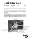
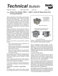
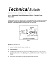
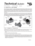
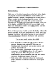
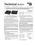
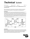
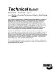
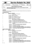
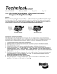
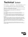
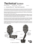
Technical
Bulletin No: TCH-013-004-A
Bulletin
Effective Date: 4/1/97
Cancels: N/A
Page: 1 of 3
THOMAS BUILT - ANTILOCK CONTROLLER GROUNDING
It has come to our attention that some older Thomas Built buses using the Bendix antilock system require a system
ground change. Contact Thomas Built for additional information or check that the antilock system is grounded as
illustrated. The following instructions are obtainable from Thomas Built.
Voltage Box (Electrical Connection Box)
Ground Screw
Figure 1
Locating the Voltage Box
The instructions presented here MUST BE USED on Thomas Built Buses equipped with Bendix AntiLock. The
antilock controller voltage ground should be moved from the electrical bus bar in the voltage box, to the voltage
box ground screw.
IMPORTANT! PLEASE READ
When working on or around a vehicle, the following general precautions should be observed.
1. Park the vehicle on a level surface, apply the parking brakes, and always block the wheels.
2. Stop the engine when working around the vehicle.
3. If the vehicle is equipped with air brakes, make certain to drain the air pressure from all reservoirs before
beginning ANY work on the vehicle.
4. Following the vehicle manufacturer’s recommended procedures, deactivate the electrical system in a manner
that removes all electrical power from the vehicle.
5. When working in the engine compartment the engine should be shut off. Where circumstances require that the
engine be in operation, EXTREME CAUTION should be used to prevent personal injury resulting from
contact with moving, rotating, leaking, heated, or electrically charged components.
6. Always wear safety glasses.
7. Do not attempt to install, remove, disassemble or assemble a component until you have read and thoroughly
understand the recommended procedures. Use only the proper tools and observe all precautions pertaining to
use of those tools.
8. Components with stripped threads or damaged parts should be replaced rather than repaired. Repairs
requiring machining or welding should not be attempted unless specifically approved and stated by the
vehicle or component manufacturer.
9. Prior to returning the vehicle to service, make certain all components and systems are restored to their proper
operating condition.
MOVING THE ANTILOCK CONTROLLER GROUND
1.
Lift the access panel at the rear of the coach and locate the voltage box on the driver’s side of the
compartment (see figure 1).
Bus Bar in
Voltage Box
Spade Connector
Controller Ground
Wires (2)
Figure 2
2.
Removing Spade Connector From Bus Bar
Locate the spade connector, with two ground wires on it (generally on the second terminal of the lower bus
bar) and remove the spade connector from the bus bar (see figure 2). Verify that vehicle power to the
AntiLock controller is off by noting that the green LED on the AntiLock Controller is no longer illuminated
even though vehicle power is on.
Wire Cutter
Spade Terminal
Controller Ground
Wires (2)
Figure 3 Cutting Spade terminal from ground wires
3.
Cut the spade connector from the two ground wires and strip 1/4" of insulation from the wires (see figure 3).
1/4” Ring Terminal
Controller Ground
Wires (2)
Figure 4 Installing Ring terminal on ground wires
4.
Install both ground wires in a single, 1/4" ring terminal and crimp the terminal on the wires (see figure 4).
Ground Screw in
center floor of
Voltage Box
Controller Ground
Wires (2)
Figure 5 Installing Ring terminal ground screw
5.
Reroute the two ground wires (with ring terminal installed) to the ground screw on the center of the floor in
the voltage box and bolt the ring terminal to this ground point (see figures 1 & 5). The green LED on the
AntiLock controller should now be illuminated when the vehicle is “powered up”.
6. Perform the Antilock “Initial Start-Up” Procedure.