1
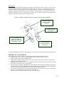
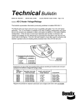
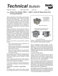
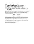
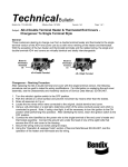
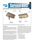
Technical Bulletin
Bulletin No: TCH-013-005
Subject:
Effective Date: 6/26/00
Cancels: NA
Page: 1 of 3
Wheel Speed Sensor Cable Chafing
Bendix Commercial Vehicle Systems is reinforcing the importance of following proper installation and service
guidelines for installing, routing and securing wheel speed sensors, sensor cables and wire harnesses for Bendix
Antilock Braking Systems (ABS).
Bendix has discovered that if wheel speed sensor cables are not properly routed and secured, the cable could rub
on rotating components, causing damage which, in rare circumstances, could result in a temporary exhaust of
brakes for a few seconds at low speeds. Although this issue has only been reported on a small number of straight
trucks and buses, Bendix recommends that when servicing ABS, you ensure proper routing and securing of wheel
speed sensor cables.
Wheel Speed Sensor Cables
Wheel speed sensor cables coming directly out of the wheel ends should be routed at least 1.5 inches away from
moving components at all points and be properly secured to air lines and the axle to prevent excess cable slack
and potential chafing damage. Ensure that the wheel speed sensor cables attached along the length of the service
brake hoses are secured with tie wraps at intervals of approximately six (6) inches and are securely connected to
the wiring harness. In addition the wheel speed sensor cable should be secured with a tie wrap three (3) inches
from the sensor.
Figure 1 - Photo of typical front wheel speed sensor cable installation
(View from Top)
Clamp
Tie Wraps
6 inches apart
Actuator
Tie Wrap 3 inches
from sensor
1.5 inch clearance at all points
from wheel or rotating
components with minimal
slack in cable
Tire
Wire Harness
Ensure all wiring routed along the frame rails is secured to frame members wherever possible. Secure every 12
inches throughout its length, preferably with non-metallic clamps or “Bow Tie” tie wraps. Route wires away
from sharp corners, heat sources, and moving or rotating components. If a harness is installed through a frame
member, grommets must be installed to prevent wire chafing. At all connectors, verify that the wires come out
straight for a minimum of three (3) inches before any bends. Be sure all connector seals are fully engaged in the
mating connector and secondary locks are snapped securely.
Figure 2 – Diagram of typical rear sensor routing and wire harness installation
Tie Wraps located
every 12 inches on
frame rail
Tie Wrap 3 inches
from sensor
1.5 inch clearance at all
points from wheels or
rotating components with
minimal slack in cable
Tie Wraps located
every 6 inches along
brake hose
As with all maintenance procedures before working on any vehicle follow the Safety Precautions outlined below.
IMPORTANT! PLEASE READ
When working on or around a vehicle, the following general precautions should be observed.
1. Park the vehicle on a level surface, apply the parking brakes, and always block the wheels.
2. Stop the engine when working around the vehicle.
3. If the vehicle is equipped with air brakes, make certain to drain the air pressure from all reservoirs before
beginning ANY work on the vehicle.
4. Following the vehicle manufacturer’s recommended procedures, deactivate the electrical system in a manner
that removes all electrical power from the vehicle.
5. When working in the engine compartment the engine should be shut off. Where circumstances require that
the engine be in operation, EXTREME CAUTION should be used to prevent personal injury resulting from
contact with moving, rotating, leaking, heated, or electrically charged components.
6. Never connect or disconnect a hose or line containing pressure; it may whip. Never remove a component or
plug unless you are certain all system pressure has been depleted.
7. Never exceed recommended pressures and always wear safety glasses.
Page 2 of 3
8.
Do not attempt to install, remove, disassemble or assemble a component until you have read and thoroughly
understand the recommended procedures. Use only the proper tools and observe all precautions pertaining to
use of those tools.
9. Use only genuine Bendix replacement parts, components, and kits. Replacement hardware, tubing, hose,
fittings, etc. should be of equivalent size, type, and strength as original equipment and be designed
specifically for such applications and systems.
10. Components with stripped threads or damaged parts should be replaced rather than repaired. Repairs
requiring machining or welding should not be attempted unless specifically approved and stated by the
vehicle or component manufacturer.
11. Prior to returning the vehicle to service, make certain all components and systems are restored to their
proper operating condition.
Bendix Commercial Vehicle Systems
901 Cleveland Street
Elyria, OH 44035
440-329-9000
Page 3 of 3