1
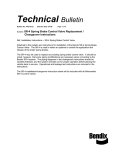
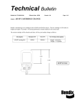
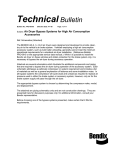
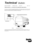
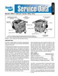
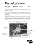
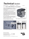
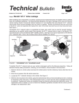
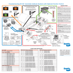
Technical Bulletin
Bulletin No: TCH-013-017
Subject:
Effective Date: 7/30/08
Cancels: N/A
Page: 1 of 2
Protect Your Bendix® ATR-1™, ATR-2™ and R-14® Relay Valves from
De-icing Chemicals
Vehicles exposed to harsh winters, de-icing and/or
other chemical sprays, often experience excessive
corrosion and contamination. As a result, these
vehicles typically need maintenance more often,
and vehicle parts exposed to de-icing chemicals
tend to require replacement sooner. For air system
components, one potential result of exposure to
corrosion and contamination can be restricted or
blocked exhaust ports which can reduce air system
performance.
R-14® Relay Valve
Cover for Balance/
Quick Exhaust Port
(Used for AntiCompound Functions)
Relay Valve Exhaust Port
Regular maintenance routines typically include inspections for corrosion and contamination. Air control
valves with smaller secondary exhaust ports, such as
the Bendix® ATR-1™ or ATR-2™ traction control valves
and R-14® relay valves (See Figure 1), are especially
important to check. These valves are often situated
in difficult-to-reach locations on the vehicle, however,
by following the steps outlined in this Bulletin, the
technician can verify that the valves are functioning
correctly.
Secondary Exhaust Ports (With Cover) are
Located Behind the Mounting Bracket
Bendix recommends that potentially affected
vehicles:
FIGURE 1 - EXAMPLES OF R-14® RELAY VALVE AND
ATR-1™ AND ATR-2™ TRACTION RELAY VALVES
•
•
Use the specific test(s) below to determine if the
valves are functioning properly
Install air system components in areas protected
from direct splash and road spray, and install splash
guards where necessary
•
Have more frequent inspection and maintenance
schedules in regions that have greater exposure
to de-icing chemicals
Early indications that maintenance is required include
reports of “brake drag” — that service brakes appear
to be slow to release following a braking or traction
control event.
When conducting the following Tests, follow all industry
standard safety guidelines, including, but not limited to,
those shown on page two of this Bulletin.
In all cases, consult your vehicle manufacturer’s
service manual for details of any further tests that they
recommend.
To Test ATR-1™ and ATR-2™ Traction Relay
Valves:
The antilock traction control (ATC) system is tested
by connecting the vehicle to a PC with the Bendix®
Relay Valve Exhaust Port
ACom ™ diagnostics program loaded. (ACom ™
software is available as a free download from www.
bendix.com). Run the ATC Valve Test provided in
ACom™ diagnostics, and verify that the brakes are fully
releasing after the ATC event. If the brakes are slow
to release, replace the traction relay valve and repeat
the above check.
To Test R-14® Relay Valves:
Visually inspect (where possible) that the balance
exhaust port cover is present on the relay valve; in
cases where the cover is missing, replace the entire
valve with a new valve. During installation, confirm
that the exhaust cover is firmly attached.
If the cover is present, verify that the R-14® relay valve
used is functioning properly by fully charging the air
system and block and hold vehicle by means other than
the air brakes. Then make several brake applications
and check for prompt application and release of each
wheel’s brakes with no perceptible lag.
If the brakes are slow to release, replace the relay valve
and repeat the above test. If the brakes continue to
exhibit slow release, refer to the troubleshooting section
in your vehicle manufacturer’s service manual.
Bulletin No: TCH-013-017
Subject:
Effective Date: 7/30/08
Cancels: N/A
Page: 2 of 2
Protect Your Bendix® ATR-1™, ATR-2™ and R-14® Relay Valves from
De-icing Chemicals
WARNING! Please READ and follow these instructions to
avoid personal injury or death:
When working on or around a vehicle, the following general
precautions should be observed at all times.
1. Park the vehicle on a level surface, apply the parking
brakes, and always block the wheels. Always wear safety
glasses.
2. Stop the engine and remove ignition key when working
under or around the vehicle. When working in the engine
compartment, the engine should be shut off and the ignition
key should be removed. Where circumstances require that
the engine be in operation, EXTREME CAUTION should be
used to prevent personal injury resulting from contact with
moving, rotating, leaking, heated or electrically charged
components.
3. Do not attempt to install, remove, disassemble or
assemble a component until you have read and thoroughly
understand the recommended procedures. Use only the
proper tools and observe all precautions pertaining to use
of those tools.
4. If the work is being performed on the vehicle’s air brake
system, or any auxiliary pressurized air systems, make
certain to drain the air pressure from all reservoirs before
beginning ANY work on the vehicle. If the vehicle is
equipped with an AD-IS® air dryer system or a dryer
reservoir module, be sure to drain the purge reservoir.
5. Following the vehicle manufacturer’s recommended
procedures, deactivate the electrical system in a manner
that safely removes all electrical power from the vehicle.
6. Never exceed manufacturer’s recommended pressures.
7. Never connect or disconnect a hose or line containing
pressure; it may whip. Never remove a component or
plug unless you are certain all system pressure has been
depleted.
8. Use only genuine Bendix® replacement parts, components
and kits. Replacement hardware, tubing, hose, fittings,
etc. must be of equivalent size, type and strength as
original equipment and be designed specifically for such
applications and systems.
9. Components with stripped threads or damaged parts
should be replaced rather than repaired. Do not attempt
repairs requiring machining or welding unless specifically
stated and approved by the vehicle and component
manufacturer.
10. Prior to returning the vehicle to service, make certain all
components and systems are restored to their proper
operating condition.
11. For vehicles with Antilock Traction Control (ATC), the ATC
function must be disabled (ATC indicator lamp should be
ON) prior to performing any vehicle maintenance where
one or more wheels on a drive axle are lifted off the ground
and moving.
Reference Service Data Sheets:
ATR-1™ Antilock Traction Relay Valve . . . . . . . . . . . .
SD-13-4811 (BW1794)
™
ATR-2 Antilock Traction Relay Valve . . . . . . . . . . . . SD-13-4812 (BW1791)
R-14® Relay Valve . . . . . . . . . . . . . . . . . . . . . . SD-03-1064 (BW1431)
ACom™ Diagnostics PC Software . . . . . . . . . . . . . . . . . . . . . . BW2329
(Free downloads available on www.bendix.com)
ABS Repair and Diagnostics DVD . . . . . . . . . . . . . . . . . . . . . . BW2538
Visit the Literature Center on www.bendix.com for free downloads of Service Data
Sheets or to order copies.
For more information, contact your local Bendix representative
or the Bendix Technical Assistance Team at 1-800-AIR-BRAKE
(1-800-247-2725) Monday through Friday, 8:00 A.M. to 6:00 P.M. EST,
and follow the instructions in the recorded message. Or, you may e-mail
the Bendix technical assistance team at: [email protected].
©2008 Bendix Commercial Vehicle Systems LLC 7/08. All Rights Reserved. Printed in U.S.A.