1
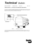
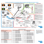
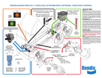
Operation and General Information Before Starting: Make sure all electrical connections on the back of the display are properly connected and all failure mode switches are turned to the OFF position. Any switches left on will create a failure warning on the dash panel and the system will not perform its Key On valve cycle. This cycle is commonly referred to as the chuff test. Connect the air supply to the rear of the display and plug in the 110 VAC power supply cord. Make sure the ignition switch is in its OFF position and then turn on the power supply. Note: At times you may want to operate the display without the buzzer sounding. If you turn the ignition key to the right “On Position” the buzzer will be ON. Turning the key to the left “Accessory Position” eliminates the buzzer only operation. You are now ready to drive the vehicle Turn the ignition switch to the ON position. The low pressure warning light and buzzer will come on. Simultaneously the antilock and traction systems will perform their chuff test. Turn the air supply valve handle at the top of the compressor to the OPEN position. Air will begin to charge the system. When the pressure reaches approximately 60 psi in both the front and rear service reservoirs the light and buzzer will go off. Push in the yellow button to release the tractor park brakes, then the red button to release the trailer park brakes. Page 1 Antilock and Traction Control operation Note: Ref. Figure 1. At each wheel you will find 10 digital wheel speed readouts protected with a green cover. Acceleration and deceleration speeds will be noted for each wheel. To begin acceleration depress the throttle pedal to approximately 1/3 travel and hold until wheel speed begins. Wheel speed at all wheels will reach 60 MPH. Figure 1. Let the wheel speed stabilize for a few seconds and then depress the brake pedal. This will put the vehicle into a simulated stop on ice. Wheel speed will cycle and stop as if in an emergency situation on ice. For traction control, depress the throttle pedal to the full travel position. A traction event will start on the drive axle with the brakes cycling left to right. Once the vehicle begins to move, the traction event will drop out and the vehicle will accelerate Page 2 to 60 MPH. Depress the brake pedal again to cycle thru an ABS event and bring the vehicle to a stop. ABS/ATC Faults and Diagnostics Note: Ref. fig. #2. On the back of each display section is a switch panel containing failure modes for that panel. For normal operation all switches should be toggled down or OFF. Toggling a switch to the ON position creates a fault. When a fault is created, a warning light on front on the dash panel will light. (Not all faults will turn the light on.) If the light does not come on, it could be related to power and ground issues. To verify that the system is working correctly turn all switches to off and reconfigure the system. Creating excessive faults at the same time may confuse the system and require a reconfiguration. Check the service manual when things do not appear to be correct. Page 3 Reference Sources www.bendix.com Reference source for free ABS software download, cataloging, service data, training materials and videos. www.meritorwabco.com Reference source for cataloging, service data and training materials. www.nexiq.com Reference source for J-1587 vehicle interface products. Recommend USB-Link # 125032 Page 4