1
SD-13-4811
®
Bendix ATR-1 AntiLock Traction Relay Valve
™
TRACTION
CONTROL
SOLENOID
MOUNTING
BRACKET
UNDRILLED
“CON” PORT
CONTROLLER MOUNTING
HOLES (4)
SERVICE
PORT
SUPPLY
PORT
DELIVERY
PORTS (4)
2 PIN SOLENOID
CONNECTOR
COVER PLATE FOR
REMOTE MOUNT
REMOTE MOUNT
ATR-1™ RELAY
VALVE
DESCRIPTION
The ATR-1™ antilock traction relay valve is a specialized air
brake valve developed for use on Bendix antilock/traction
equipped vehicles.
It is essentially three separate valves working in
combination in a single housing. An R-14® style service
relay is the base valve and is fitted with a modified cover
containing a double check valve and a traction control
solenoid. The ATR-1™ valve contains both air and electric
components to provide the service braking and traction
control (differential braking) functions. A Bendix antilock
traction controller can be mounted to the ATR-1™ valve or
a cover plate can be installed and the antilock controller
mounted elsewhere on the vehicle. When an ATR-1™ valve
is combined with an antilock traction controller the resulting
assembly is referred to as an antilock traction assembly.
The ATR-1™ valve replaces the standard relay valve used
to control the rear axle service brakes and performs the
standard relay function. Like the standard relay valve
it replaces, the ATR-1™ valve (sometimes with attached
antilock controller) is normally mounted near the service
BODY
SUPPLY
PORT
UNTAPPED PORTS
SERVICE
PORT
ALTERNATE
CASTING ON
NEWER VALVES
(NOTE THAT THE
SERVICE PORT
LOCATION IS
CHANGED)
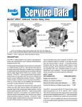
FIGURE 1 - ATR-1™ ANTILOCK TRACTION RELAY VALVE
brakes it serves. A mounting bracket, furnished with the
valve, permits either frame or cross member mounting.
All air connections on the ATR-1™ valve are identified for
ease of installation. The letter identification and air line
connections are shown below for reference.
ATR-1™ VALVE AIR CONNECTION
EMBOSSED
IDENT.
Supply (to reservoir)
SUP
Delivery (to brake chamber)
DEL
Service (to brake valve rear delivery)
SER
Control (not drilled or threaded on
ATR-1™ valve)
CON
The ATR-1™ valve is part of the R-12® family of relay valves
which includes the R-12®, R-14®, BP-R1®, AR-1™.
The internal components of the relay portion of all of these
valves are interchangeable with the R-12® valve and
therefore the same basic components are used to service
all of them. The ATR-1™ valve is available with various
crack pressures to accommodate specific applications,
however, the standard is 4 psi.
1
OPERATION
GENERAL
CONTROLLER
™
Because the ATR-1 is essentially a relay valve, the following
description of operation refers to its function in the vehicles
air brake system and does not address all of the separate
antilock components and their operation. For a description
of antilock operation, refer to the appropriate Service Data
Sheet covering the electronic controller used with the
ATR-1™ valve.
ATR-1™ ANTILOCK
TRACTION RELAY
VALVE
SERVICE BRAKES APPLYING (FIGURE 4)
Reservoir air pressure is present at the supply port and
flows through internal body and cover passages to the
supply of the normally closed (NC) traction control solenoid.
Brake application air enters the ATR-1™ valve’s service
port and is conducted to the single check valve. The check
valve diaphragm flexes in response to application pressure
and seals the passage to the open exhaust of the traction
solenoid. Air flows through the service piston then through
the center of the blend back and through a passage in the
cover to the top of the service relay piston. In response
to air pressure, the relay piston moves into contact with
FIGURE 2 - ANTILOCK TRACTION ASSEMBLY
the exhaust portion of its inlet and exhaust valve. With
the exhaust passage sealed, continued movement of the
piston unseats the inlet portion of the inlet and exhaust
valve, allowing supply air from the reservoir to flow out
the ATR-1™ valve’s delivery ports to the brake chambers.
TRACTION CONTROL
SOLENOID
SOLENOID
CONNECTOR
SERVICE
DOUBLE
CHECK VALVE
BLEND BACK
PISTON
RELAY PISTON
INLET-EXHAUST
VALVE
DELIVERY
SUPPLY
EXHAUST
FIGURE 3 - ATR-1™ ANTILOCK TRACTION ASSEMBLY
2
CONTROLLER
BRAKE
VALVE
TRACTION
SOLENOID
CHECK VALVE
RELAY PISTON
INLET EXHAUST
MODULATOR
REAR AXLE
RESERVOIR
SPRING BRAKE
FIGURE 4 - SERVICE BRAKE APPLICATION
SERVICE BRAKES HOLDING (FIGURE 5)
The air pressure being delivered to the brake chambers is
also present beneath the relay piston.
When the air pressure above and below the relay piston
is equal, the piston moves slightly allowing the inlet valve
to return to its seat. The exhaust valve remains closed.
With both the inlet and exhaust valves closed, air pressure
in the brake chambers is held stable and neither increases
nor decreases.
CONTROLLER
TRACTION
SOLENOID
BRAKE
VALVE
CHECK VALVE
RELAY PISTON
INLET EXHAUST
MODULATOR
REAR AXLE
RESERVOIR
SPRING BRAKE
FIGURE 5 - SERVICE BRAKES HOLDING
3
CONTROLLER
BRAKE
VALVE
TRACTION
SOLENOID
CHECK VALVE
RELAY PISTON
INLET EXHAUST
MODULATOR
REAR AXLE
RESERVOIR
EXHAUST
SPRING BRAKE
FIGURE 6 - SERVICE BRAKES RELEASING
SERVICE BRAKES RELEASING (FIGURE 6)
When the brake application is released, air from above
the relay piston flows back through the blend back and
service pistons to the foot brake valve and is exhausted.
As air pressure is reduced above the relay piston, pressure
beneath it lifts the piston away from the exhaust valve and
opens the exhaust passage. Air from the service brake
chambers returns to the ATR-1™ valve and flows out the
open exhaust.
TRACTION CONTROL SERVICE
BRAKE APPLICATION (FIGURE 7)
GENERAL
While under the control of an antilock traction controller,
the ATR-1™ valve’s solenoid is able to initiate a brake
application that allows the traction system to control wheel
spin upon acceleration under 25 mph. When wheel spin
is detected and the vehicle is stopped, or moving at any
CONTROLLER
BRAKE
VALVE
TRACTION
SOLENOID
CHECK VALVE
RELAY PISTON
INLET EXHAUST
MODULATOR
REAR AXLE
RESERVOIR
FIGURE 7 - TRACTION CONTROL SERVICE BRAKE APPLICATION
4
SPRING BRAKE
speed up to 25 mph, the antilock traction controller instantly
energizes the solenoid in the ATR-1™ valve which then
applies air to each of the rear axle modulators as shown
in Figure 8. The modulators are equipped with solenoid
valves also and because they are also controlled by the
controller, the solenoid valves in the appropriate modulator
are opened and closed to gently pump the brake on the
spinning wheel only. This brake application, to the spinning
wheel, forces the differential to drive the stationary or slowly
spinning wheel.
EVERY 3 MONTHS, 25,000 MILES
OR 900 OPERATING HOURS
OPERATION
4. Perform the Leakage Test described in this manual.
Reservoir air pressure is constantly present at the traction
solenoid. When the electronic controller detects wheel
spin it energizes the solenoid and in response the solenoid
opens momentarily. While the solenoid is open, air is
delivered through internal passages to the double check
valve. The check valve diaphragm flexes in response and
seals the passage to the open exhaust of the brake valve.
Once past the double check valve, air from the solenoid
flows through the rest of the valve in the same manner as
a normal service brake application and air is delivered out
the delivery ports of the ATR-1™ valve.
When the electronic controller de-energizes the solenoid,
air between the solenoid and the double check valve
returns to the solenoid and is exhausted. Air between the
relay piston and double check valve is exhausted at the
brake valve while delivery pressure is exhausted at the
main ATR-1™ valve’s exhaust port.
PREVENTIVE MAINTENANCE
Important: Review the warranty policy before
performing any intrusive maintenance procedures.
An extended warranty may be voided if intrusive
maintenance is performed during this period.
Because no two vehicles operate under identical conditions,
maintenance intervals will vary. Experience is a valuable
guide in determining the best maintenance interval for a
vehicle.
GENERAL
Perform the tests and inspections presented at the
prescribed intervals. If the ATR-1™ valve fails to function
as described, or leakage is excessive, it should be repaired
or replaced with a new or genuine Bendix remanufactured
unit, available at any authorized parts outlet.
1. Remove any accumulated contaminates and visually
inspect the exterior for excessive corrosion and physical
damage.
2. Inspect all air lines connected to the ATR-1™ valve
for signs of wear or physical damage. Replace as
necessary.
3. Test air line fittings for excessive leakage and tighten
or replace as necessary.
EVERY YEAR, 100,000 MILES, OR
3,600 OPERATING HOURS
1. Perform the Operation and Leakage Tests described
in this manual.
WARNING! PLEASE READ AND FOLLOW
THESE INSTRUCTIONS TO AVOID PERSONAL
INJURY OR DEATH:
When working on or around a vehicle, the following
general precautions should be observed at all times.
1. Park the vehicle on a level surface, apply the
parking brakes, and always block the wheels.
Always wear safety glasses.
2. Stop the engine and remove ignition key when
working under or around the vehicle. When
working in the engine compartment, the engine
should be shut off and the ignition key should be
removed. Where circumstances require that the
engine be in operation, EXTREME CAUTION should
be used to prevent personal injury resulting from
contact with moving, rotating, leaking, heated or
electrically charged components.
3. Do not attempt to install, remove, disassemble
or assemble a component until you have read
and thoroughly understand the recommended
procedures. Use only the proper tools and observe
all precautions pertaining to use of those tools.
4. If the work is being performed on the vehicle’s
air brake system, or any auxiliary pressurized air
systems, make certain to drain the air pressure
from all reservoirs before beginning ANY work
on the vehicle. If the vehicle is equipped with a
Bendix® AD-IS® air dryer system or a dryer reservoir
module, be sure to drain the purge reservoir.
5. Following the vehicle manufacturer’s recommended
procedures, deactivate the electrical system in a
manner that safely removes all electrical power
from the vehicle.
6. Never exceed manufacturer’s recommended
pressures.
5
FIGURE 8 - PARTIAL ANTILOCK TRACTION SYSTEM SCHEMATIC
6
BRAKE
CHAMBER
RETARDER SWITCH
TRACTION SWITCH
ANTILOCK DASH LAMP
TRACTION DASH LAMP
TRAILER ABS
(IF SO EQUIPPED)
EXCITER
SPEED SENSOR
MODULATOR
MODULATOR
ENGINE CONTROL MODULE
(ECM)
BRAKE
VALVE
EXCITER
SPEED SENSOR
AT-30™ ANTILOCK
TRACTION ASSY.
MODULATOR
REAR AXLE
BRAKE
MODULATOR
MODULATOR
REAR AXLE
BRAKE
7. Never connect or disconnect a hose or line
containing pressure; it may whip. Never remove
a component or plug unless you are certain all
system pressure has been depleted.
8. Use only genuine Bendix® brand replacement parts,
components and kits. Replacement hardware,
tubing, hose, fittings, etc. must be of equivalent
size, type and strength as original equipment and
be designed specifically for such applications and
systems.
9. Components with stripped threads or damaged
parts should be replaced rather than repaired. Do
not attempt repairs requiring machining or welding
unless specifically stated and approved by the
vehicle and component manufacturer.
10. Prior to returning the vehicle to service, make
certain all components and systems are restored
to their proper operating condition.
11. For vehicles with Automatic Traction Control (ATC),
the ATC function must be disabled (ATC indicator lamp should be ON) prior to performing any
vehicle maintenance where one or more wheels
on a drive axle are lifted off the ground and
moving.
OPERATION & LEAKAGE TESTS
Note: The ATR-1™ valve’s differential pressure can
be checked by applying 10 psi to the service port
and noting the pressure registered at the delivery
port. Subtract delivery port pressure from the 10 psi
service pressure to obtain the differential. Compare
the measured differential with the pressure specified for
the ATR-1™ valve’s part number (see the l.D. washer
also for the differential). NOTE: For ATR-1™ valves
not incorporating a relay piston return spring(14) the
measured differential should be approximately 4 psi.
When a spring is in use, the differential will be higher.
2. Disconnect the ATR-1 ™ valve’s two pin solenoid
connector from the controller wire harness. Apply the
probes of a volt-ohm meter to the connector leading
to the solenoid and note the resistance of the solenoid
is between 10 and 12 ohms. If resistance other than
this is noted, replace the ATR-1™ valve.
3. Apply and remove vehicle power (12 vdc) to the two pin
connector half leading to the ATR-1™ valve’s (solenoid)
while observing the brake chambers. Note that a brake
application is made and held while power is applied
to the ATR-1™ valve’s solenoid and that it is released
when power is removed.
LEAKAGE TESTS
GENERAL
A change in vehicle braking characteristics or a low
pressure warning may indicate a malfunction in one or
the other brake circuit, and although the vehicle air brake
system may continue to function, the vehicle should
not be operated until the necessary repairs have been
made and both braking circuits, including the pneumatic
and mechanical devices are operating normally. Always
check the vehicle brake system for proper operation after
performing brake work and before returning the vehicle
to service.
OPERATION TEST
1. Apply and release the brakes several times and check
for prompt application and release at each wheel. If a
prompt reaction is noted at some, but not all wheels, test
the antilock modulator between the ATR-1™ valve and
the brake chamber for proper operation. If a sluggish
response is noted at all wheels, inspect for a kinked
or obstructed air line leading to or from the ATR-1™
valve. If a complete release of the brakes is noted at
some, but not all wheels, test the antilock modulator
between the ATR-1™ valve and the brake chamber for
proper operation. If an incomplete release is noted at
all wheels, inspect for a kinked or obstructed air line
leading to or from the ATR-1™ valve.
1. Build the air system pressure to governor cut-out. Apply
a soap solution to the exhaust port. The leakage noted
should not exceed a 1” bubble in less than 3 seconds.
2. Make and hold a full brake application and apply a soap
solution to the exhaust port and around the cover where
it joins the body. The leakage noted should not exceed
a 1” bubble in less than 3 seconds at the exhaust port.
If the ATR-1™ valve fails to function as described, or
leakage is excessive, it should be replaced with a new
or genuine Bendix remanufactured unit or repaired
using a genuine Bendix maintenance kit piece number
109368, available at any authorized parts outlet.
VEHICLE PREPARATION
1. Park the vehicle on a level surface and block the wheels
and/or hold the vehicle by means other than the air
brakes.
2. Drain the air pressure from all vehicle reservoirs.
REMOVAL
1. Identify and mark or label all electrical wiring harnesses
and air lines and their respective connections on the
assembly to facilitate ease of installation.
2. Disconnect the air lines and wire harnesses.
3. Remove the controller and valve assembly from the
vehicle.
7
35
2
34
33
32
1
PRIOR INTERNAL
COMPONENT
CONFIGURATION
12
31
16
30
29
28
27
25
Assembly
of items
29-35 34
3
22
21
19
35
22
20
17
4
24
23
18
14
15
Key
1
2
3
4
5
6
7
8
9
10
11
12
13
14
15
16
17
18
Description
ECU Control
Bolts (4)
Cover
Base
Retaining Ring
Exhaust Cover
O-Ring
O-Ring
Valve Spring
Valve Retainer
Valve Assembly
Cap Screws (2)
Nuts and Washers (2)
Lock Washers (2)
Bracket
Cap Screws (2)
O-Ring
O-Ring
Key
19
20
21
22
23
24
25
26
27
28
29
30
31
32
33
34
35
36
Description
Relay Piston
Piston Spring (if used)
O-Ring
Retaining Ring
Check Valve*
O-Ring
Inlet Seat*
Check Valve Seat
O-Ring
Check Valve
Spring Seat
Spring
Inlet Seat
O-Ring
O-Ring
O-Ring
Alternate Plug*
Bolts (2)
* Note: For new style ATR-1™ valves either
both items 23 - 25, or item 35 will be present.
11
10
9
8
7
6
13
5
FIGURE 9 - ANTILOCK TRACTION ASSEMBLY EXPLODED VIEW
8
26
INSTALLATION
1. Install the assembled unit on the vehicle.
2. Reconnect all air lines and wire harnesses to the unit
using the identification made during REMOVAL step 1.
3. After installing the unit, perform the OPERATION &
LEAKAGE TESTS for the air valve before placing the
vehicle in service.
8. Separate the cover(3) from the body(4), then remove
the sealing ring(17) and o-ring(18).
9. Remove the relay piston(19) and relay piston spring(20)
from the body(4). NOTE: The relay piston spring, item
14 is not used in all valves.
10. Remove the o-ring(21) from the relay piston(19).
11. Remove the retaining ring(22).
Then, depending on the internal configuration:
DISASSEMBLY
12a.
PREPARATION FOR DISASSEMBLY
1. Remove all air fittings and plugs from the valve.
2. Mark the relationship of the valve cover(3) to the
body(4) and, if the valve is equipped with a mounting
bracket(15), mark the relationship of the bracket to the
cover and body(4).
3. Mark the relationship of the electronic controller(1) to
the cover(3).
DISASSEMBLY
Remove check valve seat(23), with o-rings(27 &
28). Remove o-rings(27 & 28) from the check valve
seat. Then remove the check valve(24), guide(25),
and spring(26).
OR,
12b.
Remove plug(35), with o-ring(34).
13. Remove the inlet seat(29) with o-rings(30 & 31), then
remove o-rings(30 & 31) from the inlet seat(29).
14. Remove the blend back piston(32) from the valve
cover(3). Remove both o-rings(33 & 34) and the piston
stop ring(35). Note: The piston stop ring may have to be
removed from the cover(3) rather than the piston(32).
The following disassembly and assembly procedure
is presented for reference purposes only. Instructions
packaged with repair and maintenance kits should always
be followed instead of the instructions presented here.
15. Do not disassemble the ATR-1™ valve any further than
described here.
CAUTION: The valve may be lightly clamped in a bench
vise during disassembly, however, over clamping will
result in damage to the valve and result in leakage
and/or malfunction. If a vise is to be used, position
the valve so that the jaws bear on the supply ports on
opposing sides of the valve body.
1. Using mineral spirits or an equivalent solvent, clean and
thoroughly dry all metal parts. Do not damage bores
with metal tools.
1. Remove and retain the four cap screws(2) that secure
the electronic controller(1) to the cover(3), then
separate and retain the controller(1), from the cover(3).
Note: In some instances a controller, Item 1, will not be
present and only a cover plate will be noted. Remove
the cover plate in the same manner described for the
controller.
3. Inspect the interior and exterior of all metal parts that
will be reused for severe corrosion, pitting and cracks.
Superficial corrosion and/or pitting on the exterior
portion of the body(4) and cover(3) is acceptable.
Replace the entire valve if the interior of the body or
cover exhibit signs of corrosion or pitting.
2. While holding the exhaust cover(6), remove the
retaining ring(5) that secures it to the body(4).
3. Remove the exhaust cover(6) along with both o-rings(7
& 8).
4. Remove the valve spring(9), valve retainer(10), and the
valve assembly(11) from the body(4).
5. Remove and retain the two long cap screws(12) and
nuts(13) that secure the cover(3) to the body(4).
6. Remove and retain the two cap screws and lock
washers(14) that secure the bracket(15) to the cover(4),
then remove and retain the bracket.
7. Remove and retain the two short cap screws(16) that
secure the cover(3) to the body(4).
CLEANING & INSPECTION
2. Wash all retained, nonmetallic components in a soap
and water solution making certain to rinse and dry
thoroughly.
4. Inspect each nonmetallic component for cracks, wear or
distortion. Replace the entire valve if these conditions
are found.
5. Inspect the bores of both the body(4) and cover(3) for
deep scuffing or gouges. Replace the entire valve if
either are found.
6. Make certain the air channel running between the top
surface of the body(1) and its supply port is clear and
free of obstruction.
7. Make certain all air channels and exhaust passages in
the valve cover(3) are clear and free of obstruction.
8. Inspect the pipe threads in the body(4) and valve
cover(3). Make certain they are clean and free of thread
sealant.
9
9. Inspect the relay piston spring(20) for signs of corrosion,
pitting and cracks. Replace as necessary.
10. Inspect all air line fittings for corrosion and replace
as necessary. Make certain to remove all old thread
sealant before reuse.
parts in the valve seat (23). Install the assembled valve
seat(23) with the check valve and valve guide(24 & 25)
into the cover(3) bore and while holding it in place install
the retaining ring(22). Make certain the retaining ring
is fully seated in its groove.
OR,
ASSEMBLY
1. Prior to assembly, lubricate all o-rings, seals, and
pistons, as well as body and cover bores, using silicone
lubricant.
2. Install the piston stop ring(35), then both the large
and small diameter o-rings(33 & 34) on the blend
back piston(32), then insert the small diameter of the
proportioning piston(32) into the bore in the cover(3).
Do not cut or pinch the o-rings.
O-Ring Identification
W
6. Install the inlet and exhaust valve return spring(9) in
the body(4).
8. While depressing the exhaust cover(6), install the
retaining ring(5) in the body(4). Make certain the
retainer(5) is fully seated in its groove in the body.
I.D.
Description
Qty.
I.D.
O.D.
W
7
O-Ring
1
0.862
1.068
0.103
8
O-Ring
1
1.424
1.63
0.103
18
O-Ring
1
3.487
3.693
0.103
21
O-Ring
1
3.234
3.512
0.139
27
O-Ring
1
1.362
1.568
0.103
28
O-Ring
1
1.114
1.254
0.07
30
O-Ring
1
1.356
1.496
0.07
31
O-Ring
1
1.176
1.316
0.07
33
O-Ring
1
1.112
1.318
0.103
34
O-Ring
1
0.737
0.943
0.103
(O-rings available in maintenance kit #109368.)
3. Install the small and large diameter o-rings (30 & 31)
on the inlet seat(29) then insert the inlet seat into the
bore in the cover(2).
Depending on the configuration/kit being installed:
4a. Install the small and large diameter o-rings (27 & 28) on
the check valve seat(23). Then install the spring(26) on
the inlet seat(29) so that the small diameter fits over and
around the air passage through the center of the inlet
seat. Install the check valve(24) and valve guide(25) in
the check valve seat(23). Note; The check valve must
be installed so that the top hat portion fits into the valve
seat(23). Install the valve guide(25) so that its flange
contains (surrounds) the coils of the large end of the
spring(26), when the valve seat (23) is installed in the
cover(3). Use a small amount of grease to hold these
10
5. Install the valve retainer(10) on the inlet and exhaust
valve(11) so that the flange of the retainer(10)
surrounds the rubber portion of the valve. Install the
inlet and exhaust valve in the body(4).
7. Install the large and small diameter o-rings(7 & 8) in the
exhaust cover(6), then install the exhaust cover in the
body(4) taking care not to damage the o-rings. Hold
the exhaust cover in place.
O.D.
Key
4b. Install the o-ring(34) onto the plug(35). Install into the
cover(3) bore and while holding it in place install the
retaining ring(22). Make certain the retaining ring is
fully seated in its groove.
9. If the valve was equipped with a relay piston return
spring(20), install the spring in the body, large diameter
first.
10. Using lubricant to hold them in place, install the large
and small sealing rings(18 & 17) on the cover(3).
11. Install the o-ring(21) on the relay piston(19), then install
the piston in the body(4).
12. Note the relationship marks made prior to disassembly,
then install the cover(3) on the body(4). Secure the
cover on the body using the two, short cap screws(16).
Again, noting the relationship marks, secure the
bracket(15) on the cover(3) and body(4) and using the
two long cap screws(12) and two nuts and washers(13).
Torque the four cap screws to 120 to 150 lb. in.
13. Install the two cap screws(14) that secure the
bracket(15) to the cover(3) and torque to 180-220
pound inches.
14. Noting the relationship marks made during disassembly,
secure the controller(1) or cover plate to the cover(3)
using the four cap screws(2). Torque the four cap
screws to 50-80 pound inches.
15. Install all air line fittings and plugs making certain thread
sealing material does not enter the valve.
16. Install the rebuilt valve on the vehicle and perform the
OPERATION AND LEAKAGE TESTS before placing
the vehicle in service.
NOTES
11
12
BW1794 © 2011 Bendix Commercial Vehicle Systems LLC 02/11 Printed in U.S.A. All Rights Reserved.