1
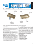
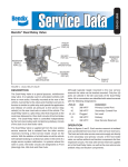
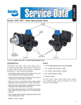
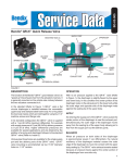
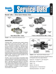
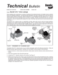
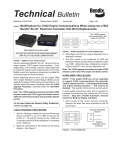
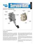
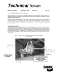
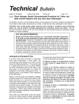
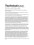
SD-03-4520
Bendix® SDS-9600™ Trailer Suspension Dump Valve
1/4" NPT
RESERVOIR
PORT
3/8" NPT
DELIVERY PORT
1/4" NPT
CONTROL
PORT
EXHAUST PORT
SHOWN WITH
DIAPHRAGM
EXHAUST PORT
SHOWN WITH
OPTIONAL SILENCER
1/4" NPT
SUPPLY PORT
3/8" NPT
DELIVERY PORT
FIGURE 1 - BENDIX® SDS-9600™ TRAILER SUSPENSION DUMP VALVE PORT IDENTIFICATION
DESCRIPTION
The SDS-9600™ trailer suspension dump valve is utilized
on spread axle trailers, to negotiate tight turns at low
speeds by limiting torsion forces on the rear trailer axle.
These forces can damage tires, frames, and suspension
components.
When activated, the SDS-9600™ trailer suspension dump
valve exhausts (dumps) a portion of the air out of the rear
trailer axle suspension taking the weight off of that axle,
and transferring it to the forward trailer axle. The trailer
can then pivot on the forward trailer axle in a turn.
Maintaining a portion of the air in the rear axle reduces
damage to the air suspension, saves on suspension and
system air, reduces time needed to re-inflate the system
when required, and reduces tire chattering, all of which may
occur if all of the air is exhausted from the suspension. The
SDS-9600™ trailer suspension dump valve then returns air
to the rear axle suspension upon driver input (deactivated)
or when vehicle speed is in excess of 10 mph.
The Bendix® SDS-9600™ trailer suspension dump valve
is a pilot operated normally open three-way valve with
a high-capacity exhaust, inversion control, and delivery
pressure hold feature. The function of the valve is to apply
delivery pressure to the rear axle of a spread axle trailer
suspension, and then to exhaust the delivery pressure
through a high-capacity exhaust upon the input of a control
signal. Upon exhaust, an internal mechanism of the trailer
suspension dump valve stops the exhausting of air and
holds the delivery pressure at a minimal pressure.
Porting is as follows:
•
•
•
•
•
(2) 3/8 inch NPT delivery ports
(1) 1/4 inch NPT control port
(1) 1/4 inch NPT supply port
(1) 1/4 inch NPT reservoir
(1) Exhaust port with Diaphragm
or optional 3/8 inch NPT port
1
FRAME RAIL
SPREAD AXLE TRAILER
2" MINIMUM
CLEARANCE
FRAME RAIL
2" MINIMUM
CLEARANCE
3/8"-16 X .50
MOUNTING
HOLES (2)
EXHAUST
90° MAXIMUM
2"
FIGURE 2 - MOUNTING THE SDS-9600™ TRAILER SUSPENSION DUMP VALVE
OPERATION
MOUNTING ORIENTATION
The SDS-9600™ trailer suspension dump valve is mounted
to the trailer frame rail or cross-member. It is preferred that
the valve be mounted on the backside of a cross-member
with the exhaust port facing down. Mounting on the top side
of a cross-member is acceptable, providing the exhaust port
is facing rearward on the vehicle. Never mount the valve
with the exhaust port facing upwards. The valve should
have at least 2 inches of clearance between the exhaust
port and any other surface. Refer to Figure 2.
PREVENTIVE MAINTENANCE
Important: The SDS-9600™ trailer suspension dump
valve is not serviceable, but must be inspected for proper
operation as a part of routine vehicle maintenance.
No two vehicles operate under identical conditions, as
a result, maintenance intervals may vary. Experience is
a valuable guide in determining the best maintenance
interval for air brake system components. At a minimum,
2
the SDS-9600™ valve should be inspected every 6 months
or 1500 operating hours, whichever comes first, for proper
operation. Should it not meet the elements of the operational
tests noted in this document, further investigation and
replacement of the valve may be required.
REMOVAL
Secure the vehicle with spring brakes or blocks. Drain the
reservoir which supplies the SDS-9600™ valve. Mark and
disconnect the connecting air lines. Remove the screws
that secure the valve to the trailer frame rail. Remove the
valve.
INSTALLATION
Typical system schematics for the SDS-9600™ valve are
shown in Figures 3 and 4.
Inspect the mounting hardware and replace if necessary.
Check connecting air lines for integrity and foreign
material, replace if necessary. Re-connect the air lines.
Check the operation of the valve by charging the system
and performing the service check as described in this
manual.
TO AUXILIARY
CONNECTOR
1/2"
RELAY
3/8"
1
2
3
ATC
SOLENOID
1/4"
R
C
CONTROLLER
D
D
D
TRAILER
SUSPENSION
DUMP VALVE
S
3/8"
S
PR-3™ PRESSURE
PROTECTION VALVE
(INTEGRATED CHECK
VALVE)
LEVELING
VALVE
1/2"
FIGURE 3 - SYSTEM DIAGRAM – PRESSURE PROTECTION VALVE WITH INTEGRATED CHECK VALVE
TO AUXILIARY
CONNECTOR
1/2"
RELAY
3/8"
1
2
3
ATC
SOLENOID
1/4"
R
C
D
CONTROLLER
3/8"
D
PR-4™ PRESSURE
PROTECTION VALVE
D
S
TRAILER
SUSPENSION
DUMP VALVE
S
SINGLE
CHECK
VALVE
LEVELING
VALVE
1/2"
FIGURE 4 - SYSTEM DIAGRAM – PRESSURE PROTECTION VALVE WITHOUT INTEGRATED CHECK VALVE
3
SERVICE CHECKS
LEAKAGE
Build the system air pressure to governor cutout. Shut
off the engine. Using a soap solution, check all lines
and fittings leading to and from the SDS-9600™ trailer
suspension dump valve for leakage and integrity. Repair
any excessive leaks - exceeding a 1" bubble in 5 secondsbefore restoring vehicle to service.
GENERAL
To properly check the functionality of the SDS-9600™ trailer
suspension dump valve there must be 15-20 PSI minimum
in the suspension air bags of the rear axle. Depending on
the weight of the trailer, this may require disconnecting the
forward axle from the air system. An empty trailer could
yield as low as 8-10 PSI in the suspension, at which point
the SDS-9600™ valve will not perform a noticeable dump
function.
These instructions assume that the TABS-6 control module
and ATC solenoid are working properly. For detailed
troubleshooting of the electrical control circuit see service
data sheet SD-13-4767.
LOADED TRAILER
Dump System Check
Drain all trailer air pressure before disconnecting any air
lines. Install a pressure gauge with a “T” fitting into one
of the delivery lines from the SDS-9600™ valve. Charge
the trailer air system reservoir to 100-120 PSI. Confirm
that there is at least 15-20 PSI of pressure in the rear axle
air bags. Activate the dump feature on the trailer. The
suspension air pressure should drop to 5 +/- 3 PSI, as
shown on the gauge in the delivery circuit.
Dump Valve Stand Alone Check
Drain all trailer air pressure before disconnecting any air
lines. Install a pressure gauge with a “T” fitting into one of
the delivery lines from the SDS-9600™ valve. Disconnect
the air line at the CON port of the SDS-9600™ valve.
Charge the trailer air system reservoir to 100-120 PSI.
Confirm that there is at least 15-20 PSI of pressure in the
rear axle air bags. Charge the CON port with 100-120 PSI
shop air (must be equal to RES pressure). The suspension
air pressure should drop to 5 +/- 3 PSI, as shown on the
gauge in the delivery circuit.
UNLOADED TRAILER
Dump System Check
Drain all trailer air pressure before disconnecting any air
lines. Disconnect the lines to the forward air bags at the
leveling valve. Plug the ports at the leveling valve. Install
a pressure gauge with a “T” fitting into one of the delivery
lines from the SDS-9600™ valve. Charge the trailer air
system reservoir to 100-120 PSI. Confirm that there is
at least 15-20 PSI of pressure in the rear axle air bags.
Activate the dump feature on the trailer. The suspension
4
air pressure should drop to 5 +/- 3 PSI, as shown on the
gauge in the delivery circuit.
Dump Valve Stand Alone Check
Drain all trailer air pressure before any air lines are
disconnected. Disconnect the lines to the forward air bags
at the leveling valve. Install a pressure gauge with a “T”
fitting into one of the delivery lines from the SDS-9600™
valve. Disconnect the line at the CON port of the
SDS-9600 ™ trailer suspension dump valve. Charge
the trailer air system reservoir to 100-120 PSI. Confirm
that there is at least 15-20 PSI of pressure in the rear axle
air bags. Charge the CON port with 100-120 PSI shop
air (must be equal to RES pressure). The suspension air
pressure should drop to 5 +/- 3 PSI, as shown on the gauge
in the delivery circuit.
BENCH TEST
Plug one delivery port of the S D S - 9 6 0 0 ™ t r a i l e r
suspension dump valve. Attach the other delivery port
to a 400 cu-in or larger reservoir, with a pressure gauge in
the delivery line or in a separate reservoir port. Charge the
SUP port to 20-80 PSI. Charge the RES port to 100-120
PSI. Confirm delivery pressure is equal to SUP pressure.
Charge the CON port with 100-120 PSI (must be equal to
the RES pressure). Valve should exhaust, and delivery
should drop to 5 +/- 3 PSI.
WARNING! PLEASE READ AND FOLLOW
THESE INSTRUCTIONS TO AVOID PERSONAL
INJURY OR DEATH:
When working on or around a vehicle, the
following general precautions should be observed
at all times.
1. Park the vehicle on a level surface, apply the
parking brakes, and always block the wheels.
Always wear safety glasses.
2. Stop the engine and remove ignition key when
working under or around the vehicle. When
working in the engine compartment, the engine
should be shut off and the ignition key should be
removed. Where circumstances require that the
engine be in operation, EXTREME CAUTION should
be used to prevent personal injury resulting from
contact with moving, rotating, leaking, heated or
electrically charged components.
3. Do not attempt to install, remove, disassemble
or assemble a component until you have read
and thoroughly understand the recommended
procedures. Use only the proper tools and observe
all precautions pertaining to use of those tools.
4. If the work is being performed on the vehicle’s
air brake system, or any auxiliary pressurized air
systems, make certain to drain the air pressure
from all reservoirs before beginning ANY work
on the vehicle. If the vehicle is equipped with an
AD-IS ® air dryer system or a dryer reservoir
module, be sure to drain the purge reservoir.
5. Following the vehicle manufacturer’s recommended
procedures, deactivate the electrical system in a
manner that safely removes all electrical power
from the vehicle.
6. Never exceed manufacturer’s recommended
pressures.
9. Components with stripped threads or damaged
parts should be replaced rather than repaired. Do
not attempt repairs requiring machining or welding
unless specifically stated and approved by the
vehicle and component manufacturer.
10. Prior to returning the vehicle to service, make
certain all components and systems are restored
to their proper operating condition.
11. For vehicles with Antilock Traction Control (ATC),
the ATC function must be disabled (ATC indicator
lamp should be ON) prior to performing any vehicle
maintenance where one or more wheels on a drive
axle are lifted off the ground and moving.
7. Never connect or disconnect a hose or line
containing pressure; it may whip. Never remove
a component or plug unless you are certain all
system pressure has been depleted.
8. Use only genuine Bendix® replacement parts,
components and kits. Replacement hardware,
tubing, hose, fittings, etc. must be of equivalent
size, type and strength as original equipment and
be designed specifically for such applications and
systems.
BW2710 © 2008 Bendix Commercial Vehicle Systems LLC. All rights reserved. 10/2008 Printed in U.S.A.
5