1
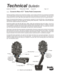
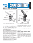
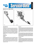
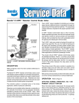
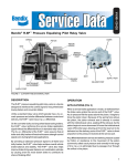
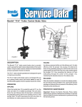
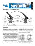
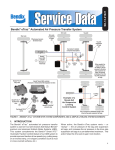
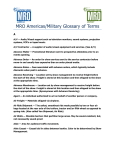
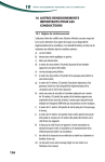
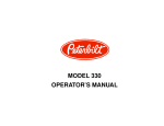
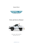
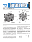
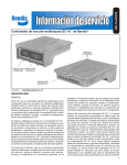
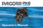
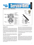
SD-03-818
Bendix® E-7™ Dual Brake Valve
MOUNTING
PLATE
SECONDARY
DELIVERY
SECONDARY
SUPPLY
SECONDARY
SUPPLY
SECONDARY
DELIVERY
SECONDARY
DELIVERY
PRIMARY
SUPPLY
PRIMARY
DELIVERY
PRIMARY
DELIVERY
PRIMARY
SUPPLY
FIGURE 1 - E-7™ DUAL BRAKE VALVE
DESCRIPTION
The Bendix® E-7™ dual brake valve is a suspended,
pedal-operated type brake valve with two separate supply
and delivery circuits for service and emergency braking,
which provides the driver with a graduated control for
applying and releasing the vehicle brakes.
™
The circuits in the E-7 dual brake valve are identified as
follows: The primary circuit portion is that portion of the
valve between the spring seat which contacts the plunger
and the relay piston; the secondary circuit portion is that
portion between the relay piston and the exhaust cavity.
The primary circuit portion of the valve is similar in operation to a standard single-circuit air brake valve, and under
normal operating conditions the secondary circuit portion
is similar in operation to a relay valve.
The primary circuit portion of the valve is part of a removable cage which also houses the relay piston and the
cage which can be removed without removing the entire
brake valve.
Both primary and secondary circuit portions of the E-7™
dual brake valve use a common exhaust protected by an
exhaust check valve.
1
OPERATION
BALANCED: SECONDARY CIRCUIT PORTION
APPLYING: NORMAL OPERATION - PRIMARY
CIRCUIT PORTION
When the air pressure on the secondary side of the relay
piston approaches that being delivered on the primary
side of the relay piston, the relay piston moves closing
the secondary inlet valve and stopping further flow of
air pressure from the supply line through the valve. The
exhaust remains closed as the pressures balance.
When the brake pedal is depressed, the plunger exerts
force on the spring seat, rubber graduating spring, and
primary piston. The primary piston which contains the
exhaust valve seat, closes the primary exhaust valve. As
the exhaust valve closes, the primary inlet valve is moved
off its seat allowing primary air pressure to flow out the
delivery port.
APPLYING: NORMAL OPERATION SECONDARY CIRCUIT PORTION
When the primary inlet valve is moved off its seat, air is
permitted to pass through the bleed passage and enters the
relay cavity. The air pressure moves the relay piston, and
the relay piston, which contains the exhaust seat, closes
the secondary exhaust valve. As the secondary exhaust
valve closes, the secondary inlet valve is moved off its seat
allowing secondary air pressure to flow out the delivery
port. Because of the small volume of air required to move
the relay piston, action of the secondary circuit portion of
the valve is almost simultaneous with the primary circuit
portion.
APPLYING: LOSS OF AIR IN SECONDARY
CIRCUIT
Should air be lost in the secondary circuit, the primary
circuit portion will continue to function as described above
under Normal Operation: Primary Circuit Portion.
APPLYING: LOSS OF AIR IN PRIMARY CIRCUIT
Should air be lost in the primary circuit, the function will
be as follows: As the brake pedal is depressed and no air
pressure is present in the primary circuit supply and delivery
ports, the primary piston will mechanically move the relay
piston allowing the piston to close the secondary exhaust
valve and open the secondary inlet valve and allow air
pressure to flow out the delivery port.
BALANCED: PRIMARY CIRCUIT PORTION
When air pressure delivered to the brake actuators and air
pressure in the cavity on the delivery side of the primary
piston equals the mechanical force of the brake pedal
application, the primary piston will move and the primary
inlet valve will close, stopping the further flow of air from
the primary supply line through the valve. The exhaust
valve remains closed preventing any escape of air through
the exhaust port.
2
When applications in the graduating range are made, a
balanced position in the primary portion is reached as
the air pressure on the delivery side of the primary piston
equals the effort exerted by the driver’s foot on the pedal.
A balanced position in the secondary portion is reached
when air pressure on the secondary side of the relay piston
closely approaches the air pressure on the primary side
of the relay piston.
When the brake pedal is fully depressed, both primary
and secondary inlet valves remain open and full reservoir
pressure is delivered out the delivery ports.
RELEASING: PRIMARY CIRCUIT PORTION
With the brake pedal released, mechanical force is
removed from the spring seat, rubber graduating spring,
and primary piston. Air pressure and spring load moves the
primary piston, opening the primary exhaust valve allowing
air pressure in the primary delivery line to exhaust out the
exhaust port.
RELEASING: SECONDARY CIRCUIT PORTION
With the brake pedal released, air is exhausted from the
primary side of the relay piston. Air pressure and spring
load move the relay piston, opening the secondary exhaust
valve allowing air pressure in the secondary delivery line
to exhaust out the exhaust port.
PREVENTIVE MAINTENANCE
Important: Review the Bendix Warranty Policy before
performing any intrusive maintenance procedures. A
warranty may be voided if intrusive maintenance is
performed during the warranty period.
No two vehicles operate under identical conditions, as a
result, maintenance intervals may vary. Vehicles operating
in extreme duty commercial vocations, such as refuse and
transit, may experience accelerated wear of brake pedal
components when the recommended routine maintenance
is not performed. The wear may be compounded with the
use of high-offset brake pedals that increase the side-load
forces into the pedal assembly. Experience is a valuable
guide to determining the best maintenance interval for air
brake components. At a minimum, the E-7™ valve should
be inspected every 6 months or 1500 operating hours,
whichever comes first, for proper operation. Should the
INLET-EXHAUST
ASSEMBLY (1)
EXHAUST CHECK
VALVE
RETAINER (17)
SCREW (21)
O-RING (2)
WASHER (22)
O-RING (3)
DIAPHRAGM (13)
RELAY SPRING (5)
RETAINER (20)
INLET-EXHAUST
ASSEMBLY (4)
O-RING (11)
O-RING (9)
O-RING (7)
O-RING (6)
O-RING (12)
PISTON SPRING (8)
SPRING SEAT NUT (16)
RETAINER (18)
STEM SPRING (23)
RUBBER SPRING (10)
SPRING SEAT (15)
RUBBER SPRING SEAT (19)
LOCK NUT (14)
STOP BUTTON
PLUNGER
ROLLER
FULCRUM PIN
PEDAL
SEALING
RINGS
MANIFOLD*
*OPTIONAL MANIFOLD FOR INSTALLATIONS
REQUIRING SUPPLY & DELIVERY LINE
CONNECTIONS ON ENGINE SIDE OF ENGINE
COMPARTMENT BULKHEAD.
FIGURE 2 - E-7™ DUAL BRAKE VALVE
3
PLUNGER
MOUNTING PLATE
PLUNGER
COTTER PIN
COTTER PIN
FULCRUM PININSTALLED IN THE
DIRECTION OF THE
PEDAL PAD
FULCRUM PIN INSTALLED IN THE
DIRECTION OF THE
PEDAL PAD
PEDAL OFFSET
ROLLERS
BRAKE PEDAL PAD
PEDAL OFFSET
FIGURE 3 - E-7™ BRAKE VALVE ASSEMBLIES WITH OFFSET PEDALS
E-7™ valve not meet the elements of the operational tests
noted in this document, further investigation and service
of the valve may be required.
Every 3 months, 25,000 miles, or 900 operating
hours:
Misalignment between the pedal components and valve will
cause valve leakage during a brake application. Inspect
the pedal to see that all cotter pins, rollers, and pivot pins
are in place. Damaged or missing components should be
replaced before operation of the vehicle. Parts showing
signs of excessive wear should also be replaced.
Free pedal travel should be checked as follows: Check
to be certain the plunger is in contact with spring seat.
The stop button should be adjusted so that the roller and
plunger just contact.
be liberally coated with barium grease per BW-204-M
(Bendix part number 246671). These parts may require
more frequent lubrication if the vehicle’s interior is regularly
pressure washed as part of a maintenance program.
Clean the exhaust cover as needed depending on type
of service.
On high-offset pedal applications, the cotter pin that
retains the fulcrum pin may become damaged. This can
be identified by wear marks on the side of the mounting
plate. To maximize the life of the cotter pin, the fulcrum
pin should be installed such that the cotter pin is located
on the same side of the mounting plate as the brake pedal
pad. If the cotter pin is found to be opposite of the pedal
pad, the fulcrum pin should be reversed and secured with
a new cotter pin.
SERVICE CHECKS
To identify if the pedal components are excessively worn,
grab the pedal at the foot pad and push side to side. If
the pedal has movement over .250 inches then the pedal,
mounting plate, and fulcrum pin, should be replaced.
Other signs of wear that will require inspection are
deterioration of the boot, plunger wear, and wear in the
mounting plate at the fulcrum pin holes. If the wear is
excessive, the fulcrum pin holes become oval in shape.
The plunger bore and fulcrum pin holes should always
4
OPERATING
Check the delivery pressure of both primary and secondary
circuits using test gauges known to be accurate. Depress
the pedal to several positions between the fully released
and fully applied positions, and check the delivered pressure
on the test gauges to see that it varies proportionately with
the movement of the brake pedal.
When the treadle is fully applied, the reading on the test
gauge should fall off to zero promptly when the application
is released. It should be noted that the primary circuit
delivery pressure will be about 2 psi greater than secondary
circuit delivery pressure with primary and secondary circuit
supply reservoirs at the same pressure. This is normal in
this valve.
IMPORTANT
An increase in stopping distance or a low pressure warning
indicates a malfunction in one or the other brake circuit,
and although the vehicle air brake system may continue
to function, the vehicle should not be operated until the
necessary repairs have been made and both braking
circuits are operating normally.
LEAKAGE CHECK
1. Make and hold full brake application.
2. Coat the exhaust port and body of the brake valve with
soap solution.
3. Leakage is not to exceed a 1” bubble in 3 seconds in
both the applied and released position.
If the brake valve does not function as described above or
leakage is excessive, it is recommended that it be replaced
with a genuine Bendix® new or remanufactured unit,
available at your local authorized Bendix® parts outlet.
MV-3®
MANIFOLD
VALVE
REMOVAL (IF NECESSARY)
1. Block the wheels or hold the vehicle by means other
than air brakes and exhaust air pressure from reservoirs
supplying air to the E-7™ valve.
2. In most installations, the E-7™ brake valve internal parts
may be removed and replaced by removing the three
cap screws which hold the pedal assembly in place and
removing the pedal assembly. The internal parts may
then be removed from the E-7™ valve as described in
disassembly.
3. If it is necessary to remove the E-7™ valve from the
engine compartment bulkhead, identify the two supply
and two delivery lines to their respective ports as
connected to the brake valve. There may also be air
lines to other brake devices inside the cab, which
should be properly identified before disconnecting. In
the case of a manifold type installation, the three cap
screws which hold the manifold to the brake valve may
be removed and the brake valve removed.
DISASSEMBLY (REFER TO FIGURE 2)
1. Remove retainer, (18). Remove the lower static piston
assembly.
2. Fashion a hook from a piece of wire and insert hook
through inlet-exhaust valve of upper static piston
assembly. Pull firmly and remove upper static piston
assembly.
TP-5™ TRACTOR
PROTECTION VALVE
TRAILER
CONTROL
VALVE
SLACK
ADJUSTER
SLACK
ADJUSTER
BRAKE
CHAMBER
DUAL BRAKE
VALVE
DOUBLE
CHECK
VALVE
SPRING
BRAKES
QUICK
RELEASE
VALVE
AIR DRYER
BP-R1®
BOBTAIL
PROPORTIONING
VALVE
SUPPLY
RESERVOIR
COMPRESSOR
#1 SERVICE
RESERVOIR
#2 SERVICE
RESERVOIR
FIGURE 4 - TYPICAL PIPING SCHEMATIC
5
DISASSEMBLY (UPPER STATIC PISTON
ASSEMBLY)
1. Remove o-rings (2) and (3).
2. Remove retaining ring (17), and remove secondary
circuit inlet exhaust assembly (1).
DISASSEMBLY OF LOWER STATIC ASSEMBLY
1. Apply firm pressure on spring seat (19), which will
compress piston return spring. Locking groove in piston
is now accessible through rectangular opening in lower
static piston body. Insert wire or screwdriver into locking
groove, thus holding static piston spring in compressed
position.
2. Insert blade of screwdriver through relay piston exhaust
passage into slot of stem, and remove lock nut (14),
being careful not to nick the exhaust seat of the relay
piston.
3. Remove spring seat (15), stem spring (23), spring seat
nut (16), rubber spring seat (19), and rubber spring,
(10).
4. Relay piston, relay spring, (5) and stem bolt may now
be removed.
5. Removal of screwdriver or wire from locking groove
will permit spring load to push the primary circuit piston
from the lower static piston. Note: Care should be used
when removing tool from locking ring because of spring
load.
6. Remove o-rings (6 & 7) from relay piston and o-ring,
(9) from primary circuit piston.
7. Remove o-rings (11 & 12) from lower static piston.
8. Remove large retaining ring (20) from lower static
piston, and remove primary circuit inlet/exhaust valve
assembly (4).
DISASSEMBLY-EXHAUST CHECK VALVE
Some E-7™ brake valves have an air exhaust check valve
(13, 21 & 22) as shown on Figure 2. If so, remove screw
(21), and washer (22), and discard diaphragm (13). Replace
the exhaust check valve diaphragm (13) and secure with
the screw (21) and washer (22).
ASSEMBLY
Note: Before assembly, lubricate all o-rings, bores, and
mating surfaces with silicone lubricant, pc. no. 291126 (Dow
Corning 55-M). Do not lubricate rubber spring.
1. Install secondary circuit inlet-exhaust assembly (1) in
upper static piston, making certain retaining ring (17)
is engaged in groove of upper static piston bore.
2. Install o-rings (2 & 3) on upper static piston and install
in valve body.
6
3. Install primary circuit inlet-exhaust assembly in lower
static piston making certain retaining ring (20) is
engaged in groove of lower static piston bore.
4. Install three o-rings (2 of 11), and (12) in grooves of
lower static piston assembly. (Note: The larger diameter
o-ring is installed in groove nearest to bottom of piston
assembly.)
5. Install o-rings (6) and (7) on relay piston and o-ring (9)
on primary circuit piston.
6. Carefully clamp primary circuit piston in a soft-jawed
vise taking care not to damage the exhaust seat or the
outside diameter. Assemble the rubber spring, (10) over
the center stem of the center of the piston, then the
spring seat (19) and the spring seat nut (16). Tighten
the spring seat nut until the end of the piston stem and
the spring seat nut are flush.
7. Insert relay piston spring (5) and relay piston in top end
of lower static piston, and primary circuit piston spring
(8) and primary circuit piston assembly in the bottom
of lower static piston.
8. Install stem bolt through bore of relay piston, invert
entire lower static piston assembly and position over
a screwdriver mounted in a vise. Engage screwdriver
blade in slot in head of stem.
9. Depress primary circuit piston assembly against spring
until locking groove is accessible through rectangular
hole in side of lower static piston. Engage a screwdriver
or wire in locking groove and release pressure on
piston.
10. Install stem spring, (23), spring seat, (15) and lock nut,
(14). Torque to 20-30 inch Ibs.
11. Install lower static piston assembly in valve body. Install
retainer, (18), making certain locking tabs engage boss
on valve body.
PEDAL ASSEMBLY
Install pedal assembly using three cap screws. On offset
pedal applications, be sure that the cotter pin securing the
fulcrum pin is on the same side of the mounting plate as
the pedal pad. Check to be certain plunger is in contact
with spring seat. The stop button should be adjusted so
that the roller and plunger contact after adjustment, roller
should be able to be turned freely by thumb.
SERVICE CHECKS
OPERATING
Check the delivery pressure of both primary and secondary
circuits using accurate test gauges. Depress the pedal
to several positions between the fully released and fully
applied positions, and check the delivered pressure on the
test gauges to see that it varies proportionately with the
movement of the brake pedal.
When the treadle is fully applied, the reading on the test
gauge should fall off to zero promptly when the application
is released. It should be noted that the primary circuit
delivery pressure will be about 2 psi greater than secondary
circuit delivery pressure with primary and secondary circuit
supply reservoirs at the same pressure. This is normal in
this valve.
4. If the work is being performed on the vehicle’s
air brake system, or any auxiliary pressurized air
systems, make certain to drain the air pressure
from all reservoirs before beginning ANY work
on the vehicle. If the vehicle is equipped with
an AD-IS® air dryer system or a dryer reservoir
module, be sure to drain the purge reservoir.
LEAKAGE
5. Following the vehicle manufacturer’s recommended
procedures, deactivate the electrical system in a
manner that safely removes all electrical power
from the vehicle.
1. Make and hold full brake application.
2. Coat the exhaust port and body of the brake valve with
soap solution.
3. Leakage not to exceed a 1” bubble in 3 seconds in both
the applied and released position.
If the brake valve does not function as described above or
leakage is excessive, it is recommended that it be replaced
with a genuine Bendix new or remanufactured unit,
available at your local authorized Bendix parts outlet.
GENERAL SAFETY GUIDELINES
WARNING! PLEASE READ AND FOLLOW
THESE INSTRUCTIONS TO AVOID PERSONAL
INJURY OR DEATH:
When working on or around a vehicle, the following
general precautions should be observed at all times.
1. Park the vehicle on a level surface, apply the
parking brakes, and always block the wheels.
Always wear safety glasses.
2. Stop the engine and remove ignition key when
working under or around the vehicle. When
working in the engine compartment, the engine
should be shut off and the ignition key should be
removed. Where circumstances require that the
engine be in operation, EXTREME CAUTION should
be used to prevent personal injury resulting from
contact with moving, rotating, leaking, heated or
electrically charged components.
6. Never exceed manufacturer’s recommended
pressures.
7. Never connect or disconnect a hose or line
containing pressure; it may whip. Never remove
a component or plug unless you are certain all
system pressure has been depleted.
8. Use only genuine Bendix® replacement parts,
components and kits. Replacement hardware,
tubing, hose, fittings, etc. must be of equivalent
size, type and strength as original equipment and
be designed specifically for such applications and
systems.
9. Components with stripped threads or damaged
parts should be replaced rather than repaired. Do
not attempt repairs requiring machining or welding
unless specifically stated and approved by the
vehicle and component manufacturer.
10. Prior to returning the vehicle to service, make
certain all components and systems are restored
to their proper operating condition.
11. For vehicles with Antilock Traction Control (ATC),
the ATC function must be disabled (ATC indicator
lamp should be ON) prior to performing any vehicle
maintenance where one or more wheels on a drive
axle are lifted off the ground and moving.
3. Do not attempt to install, remove, disassemble
or assemble a component until you have read
and thoroughly understand the recommended
procedures. Use only the proper tools and observe
all precautions pertaining to use of those tools.
7
8
BW1428 © 2008 Bendix Commercial Vehicle Systems LLC. All rights reserved. 11/2008 Printed in U.S.A.