Transcript
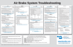
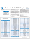
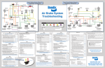
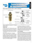
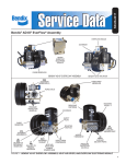
Typical School Bus Air System Schematic with a Bendix® AD-IS® Air Dryer Wheel Speed Sensor and Tone Ring Typical School Bus Air System Schematic with a Bendix® AD-9® Air Dryer Wheel Speed Sensor and Tone Ring Park Control Valve Air Disc Brake Air Disc Brake School Bus Air Brake System Troubleshooting Bendix® BVA-85™ Door Interlock Kit Dual Brake Valve w/ BVA-85™ Brake Valve Actuator Traction Solenoid Spring Brake Control Valve Relay Valve C Quick Release Valve Stop Light Switch Antilock Electronic Controller Bendix® AD-IS® Air Dryer Low Pressure Indicator Governor Rear Axle Reservoir Bendix Charging To Accessories Manual Drain Valve TEST 1 Governor cut-out / Low pressure warning / Pressure build-up VEHICLE PARKED, WHEELS CHOCKED OK Not OK CHECKLIST 1 If the low pressure warning lamp or buzzer doesn’t come on: 1. Check the warning lamp wiring. 2. Check the warning lamp bulb. 3. Repair or replace the buzzer, bulb or low pressure warning switch(es). Drum Brake NOTE: A leak detector or soap solution will aid in locating the faulty component. 1. Loose service lines and fittings 2. Park control valve 3. Stoplight switch 4. Spring brake chamber, service chamber and/or brake chamber diaphragms 5. Service brake relay valves 6. Dual brake valve 7. Inverting relay spring brake control valve (where applicable – usually found on the spring brake relay valve) straight trucks and buses 8. Double check valve If the automatic slack adjuster is not adjusting, repair or replace to obtain the desired setting. CAUTION: If the brake chamber push rod travel exceeds the allowable stroke, identify and correct the root cause of the excess stroke. Do not make manual adjustments of an automatic slack adjuster once it can no longer automatically adjust the brakes. Manual adjustment DOES NOT fix the underlying wheel-end adjustment. As soon as possible, have the vehicle inspected by a qualified technician or consult the manufacturer’s troubleshooting guidelines to find and fix the problem. RETEST TO VERIFY PROPER OPERATION OF ALL ITEMS REPAIRED OR REPLACED. 1. Repair, replace or adjust the governor as necessary after ensuring the compressor unloader mechanism is operating correctly. If the low pressure warning occurs below 60 psi: 1. Check the dash gauge with test gauge known to be accurate. 2. Repair or replace the faulty low pressure indicator switch. If the compressor build up time exceeds 40 seconds or is considerably greater than the permanent record figure: 1. Examine the compressor air inlet filter and inlet line checking for restrictions, damage or wear. Clean or replace the filter or inlet line as necessary. 2. Check the compressor discharge port and line for excessive carbon. Clean or replace the discharge line as necessary. If carbon is present, find the cause of the excessive heat. 3. With the system fully charged and governor in the unloaded mode, listen at the compressor inlet for leakage. If leakage can be heard, remove the unloaders and repair or replace as necessary. RETEST TO VERIFY PROPER OPERATION OF ALL ITEMS REPAIRED OR REPLACED. Not OK MAKE ALL NECESSARY REPAIRS BEFORE PROCEEDING TO TEST 3; SEE CHECKLIST 2 FOR COMMON CORRECTIONS. CHECKLIST 2 If there is excessive leakage in the supply side of the pneumatic system, one or more of the following devices could be causing the problem: NOTE: A leak detector or soap solution will aid in locating the faulty component. Supply lines and fittings Low pressure indicator(s) Service brake relay valve(s) Spring brake relay valve (where applicable) Dual brake valve Park control valve System safety valve(s) in the supply reservoir and/or air dryer Governor (may be mounted on the air dryer as illustrated, on the compressor, or remotely) Compressor discharge line RETEST TO VERIFY PROPER OPERATION OF ALL ITEMS REPAIRED OR REPLACED. TEST 4 Leakage service air delivery FULL PRESSURE, ENGINE STOPPED, PARKING BRAKES RELEASED OK Not OK 1. Make and hold an 80-90 psi brake application. This can be accomplished by using the Bendix® BVA-85™ brake valve actuator. If the vehicle is not equipped with a BVA-85™ brake valve actuator, an assistant should be used to maintain a constant brake application during these tests. 2. Allow pressure to stabilize for 1 minute; then begin timing for 2 minutes while watching the dash gauges for a pressure drop. A 4 psi drop within 2 minutes is allowable for either service reservoir. 3. Check brake chamber push rod travel (refer to chart for allowable tolerances). With the parking brakes released and service brakes applied with 80 to 90 psi of air pressure to the service chambers. Brake Maximum Allowable Max Allowable Chamber Size Stroke Stroke - Long Stroke __________________________________________________ 12 1-3/8” 1-3/4” 16 1-3/4” 2” 20 1-3/4” 2” 24 1-3/4” 2” 24 (Max Stroke) 2-1/2” 30 2” 2-1/2” 4. Check the angle formed between the brake chamber push rod and slack adjuster arm. It should be approximately 90° in the applied position (80-90 psi) and the same across the axle. MAKE ALL NECESSARY REPAIRS BEFORE PROCEEDING TO TEST 5; SEE CHECKLIST 4 FOR COMMON CORRECTIONS. TEST 5 Manual Parking Brake Operation FULL PRESSURE, ENGINE IDLING 600-900 RPM OK Not OK Manually operate the park control, yellow button valve, and note that parking brakes apply and release promptly as the control valve button is pulled out and pushed in. MAKE ALL NECESSARY REPAIRS BEFORE PROCEEDING TO TEST 6; SEE CHECKLIST 5 FOR COMMON CORRECTIONS. CHECKLIST 5 If sluggish performance is noted check for the following: 1. 2. 3. 4. 5. Secondary Parking (Control) Automatic Slack Adjuster Accessories Stop Light Switch Pressure Protection Valve Dented or kinked lines Improperly installed hose fitting A faulty quick release valve or spring brake control valve Damaged or improperly installed spring brake chamber and/or service chambers Foundation brake component binding, improper installation and/or lack of lubrication TEST 6 Continued OK Not OK 3. “Pop” Pressure Vehicle Test Procedure (Continued) Install an accurate “shop standard” pressure gauge in the secondary service reservoir. Build pressure in the service reservoirs until the compressor cut-out is reached, shut the engine off. Fully open the manual drain valve on the primary service reservoir allowing the reservoir to drain completely. Open the secondary reservoir’s manual drain valve creating a bleed rate of approximately 20-50 psi/min. Monitor the pressure gauge noting the pressure at which the parking control automatically “pops”. This is not a Federal requirement - See Note in previous column. 4. Close the drain cocks, recharge the system and drain the rear axle primary reservoir to 0 psi. The front axle reservoir should retain most of its pressure. 5. With no air pressure in the rear axle reservoir, make and release a brake application. A. Front axle brakes should apply and release. B. If the vehicle is equipped with a spring brake modulating valve, the rear axle brakes should also apply and release by exhausting spring brake air. Note: Bendix is not aware of any federal legislation that specifies the pressure at which the YELLOW parking brake control valve must automatically “trip” to apply the vehicle parking brakes. This includes the Federal Motor Carrier Safety Regulations (FMCSR) for in-use vehicles, the CVSA out-of-service criteria, and the Federal Motor Vehicle Safety Standards (FMVSS) for newly manufactured vehicles. Although the “trip” pressure for the parking brake control valve is not stipulated for in-use or newly manufactured vehicles, a parking brake control valve “trip” pressure of 20-40 psi is currently (02/2009) specified as part of the Commercial Driver License in the CDL Manual. The CDL Manual is not consistent with the regulations cited above. See Bulletin TCH-003-051. continued . . . Automatic Slack Adjuster Rear Axle Reservoir Governor Single Check Valve BW902 BW1114 BW1231 BW1555 BW2780 BW2786 BW5057 BW2197 SD-13-4815 SD-13-4863 GENERAL SAFETY GUIDELINES When working on or around a vehicle, the following general precautions should be observed at all times. RETEST TO VERIFY PROPER OPERATION OF ALL ITEMS REPAIRED OR REPLACED. Note: The optional Bendix® BVA-85™ actuator for Bendix® E-6® -, E-8P™-, and E-10™based brake valve configurations, plus the door interlock kit (Pc. No. K036675), is intended to provide an approximately 40 psi service brake application to all wheels when the following conditions are met; • Passenger door is open • RED crossing flashers are ON • Vehicle speed is below 3 mph Indication is provided to the operator in the event that the control pressure to the BVA-85™ actuator drops below the minimum pressure required to hold the bus. Drum Brake Wheel Speed Sensor and Tone Ring School Bus Air Brake Systems (Small version of BW2872) Bendix Quick Reference Catalog Air Brake System Troubleshooting Wallchart Brake Balance Procedure Troubleshooting Bendix® ESP® Stability System Wallchart Troubleshooting Bendix® ESP® Stability System Air Brake Handbook BVA-85™ Brake Valve Actuator EC-30™ ABS Controller EC-60™ ABS Controller CHECKLIST 6 If the vehicle fails to pass the tests outlined, then check the following components for leakage and proper operation: Fittings Kinked hose or tubing Pressure protection valves Double check valves Parking control valve Relay valves (antilock modulators) Inverting relay spring brake control valve (optional) Manual Drain Valve Spring Brake Chamber Visit www.bendix.com or www.foundationbrakes.com for Service Data Sheets and other literature such as the following: WARNING! PLEASE READ AND FOLLOW THESE 1. 2. 3. 4. 5. 6. 7. Air Pressure Gauge Front Axle Reservoir Supply Reservoir MAKE ALL NECESSARY REPAIRS BEFORE PROCEEDING; SEE CHECKLIST 6 FOR COMMON CORRECTIONS. RETEST TO VERIFY PROPER OPERATION OF ALL ITEMS REPAIRED OR REPLACED. TEST 6 Dual circuit system integrity check (emergency braking) and/or automatic application of the parking brake OK Not OK FULL PRESSURE, ENGINE STOPPED, PARKING BRAKES RELEASED 1. Drain the front axle or secondary reservoir to 0 psi. The rear axle or primary reservoir should retain most of its pressure. 2. With no air pressure in the front axle reservoir, make a brake application. A. The rear axle brakes should apply and release when the application is released. B. The stop lamps should light and go off when the application is released. 3. “Pop” Pressure Vehicle Test Procedure Low Pressure Indicator Bendix® AD-9® Air Dryer Compressor Spring Brake Control Valve Relay Valve Antilock Electronic Controller Safety Valve Notes: The color coding of the brake system schematic follows TMC Recommended Practice #423. Air disc & drum brake actuation combined on a single axle are shown for pictorial purposes only. CHECKLIST 4 If there is excessive leakage in the service side of the pneumatic system, one or more of the following devices could be causing the problem: MAKE ALL NECESSARY REPAIRS BEFORE PROCEEDING TO TEST 4. If the governor cut-out is higher or lower than specified by the vehicle manual: 1. 2. 3. 4. 5. 6. 7. 8. 9. TEST 3 Pressure Modulator Valve and Traction Control Valve Chuff FULL PRESSURE, ENGINE STOPPED, PARKING BRAKES RELEASED OK Not OK NOTE: The Bendix® EC-60™ electronic controller will perform a pressure modulator valve (PMV) chuff test on all installed modulators in the following order: 1. Steer Axle Right PMV 2. Steer Axle Left PMV 3. Drive Axle Right PMV 4. Drive Axle Left PMV 5. Additional Axle Right PMV 6. Additional Axle Left PMV 7. Drive Axle Traction Control Valve (TCV) The pattern will then repeat itself. See appropriate Service Data Sheet for repairs. MAKE ALL THE NECESSARY REPAIRS BEFORE PROCEEDING TO TEST 2; SEE CHECKLIST 1 FOR COMMON CORRECTIONS. TEST 2 Leakage (reservoir air supply) For additional information refer to the video, Assessing Air Brake OK System Air Leakage (Bendix® part number BW2327 - CD) FULL PRESSURE, ENGINE STOPPED, PARKING BRAKES APPLIED 1. Allow the air pressure to stabilize for at least 1 minute. 2. Observe the dash gauge pressures for 2 minutes and note any pressure drop. A 4 psi drop within 2 minutes is allowable for either service reservoir. Wheel Speed Sensor and Tone Ring Make and hold a brake application. When ignition power is applied, each pressure modulator valve (PMV) solenoid is briefly energized. If the air system is fully charged and the service brake pedal is depressed during ignition, the modulator creates a single, sharp audible “chuff” of air pressure. The modulators are energized in a certain pattern, as follows: right front, left front, right rear, left rear. This test is performed only when the vehicle is stationary (if the vehicle moves the chuff test will not be performed). 1. Drain all the reservoirs to 0 psi. 2. Start the engine and run at fast idle. The low pressure warning should be on. Note: on vehicles equipped with ABS, the warning lamp will also come on momentarily when the ignition is turned on. On some systems, such as the Bendix® AD-IS® dryer system (illustrated), reservoirs may not fill simultaneously and one reservoir may fill to 110 psi before the other starts to fill. 3. Low pressure warning; dash warning lamp should go off above 60 psi. 4. Build up time; pressure should build from 85-100 psi within 40 seconds. 5. Governor cut-out; cuts-out at the correct pressure, 135 psi (maximum). 6. Governor cut-in; reduce the service air pressure to governor cut-in. The difference between cut-in and cut-out pressure must not exceed 30 psi. Primary Spring Brake Chamber Air Pressure Gauge Front Axle Reservoir C Quick Release Valve Brake Chamber Automatic Slack Adjuster Antilock Modulator (4 places) Traction Solenoid To Accessories Compressor Brake Chamber Bendix® BVA-85™ Door Interlock Kit Dual Brake Valve w/ BVA-85™ Brake Valve Actuator Antilock Modulator (4 places) Coach and School Bus: Automatic Slack Adjuster Park Control Valve INSTRUCTIONS TO AVOID PERSONAL INJURY OR DEATH: 1. Park the vehicle on a level surface, apply the parking brakes, and always block the wheels. Always wear safety glasses. 2. Stop the engine and remove ignition key when working under or around the vehicle. When working in the engine compartment, the engine should be shut off and the ignition key should be removed. Where circumstances require that the engine be in operation, EXTREME CAUTION should be used to prevent personal injury resulting from contact with moving, rotating, leaking, heated or electrically charged components. 3. Do not attempt to install, remove, disassemble or assemble a component until you have read and thoroughly understand the recommended procedures. Use only the proper tools and observe all precautions pertaining to use of those tools. 4. If the work is being performed on the vehicle’s air brake system, or any auxiliary pressurized air systems, make certain to drain the air pressure from all reservoirs before beginning ANY work on the vehicle. If the vehicle is equipped with a Bendix® AD-IS® air dryer system or a dryer reservoir module, be sure to drain the purge reservoir. 5. Following the vehicle manufacturer’s recommended procedures, deactivate the electrical system in a manner that safely removes all electrical power from the vehicle. 6. Never exceed manufacturer’s recommended pressures. 7. Never connect or disconnect a hose or line containing pressure; it may whip. Never remove a component or plug unless you are certain all system pressure has been depleted. 8. Use only genuine Bendix® brand replacement parts, components and kits. Replacement hardware, tubing, hose, fittings, etc. must be of equivalent size, type and strength as original equipment and be designed specifically for such applications and systems. 9. Components with stripped threads or damaged parts should be replaced rather than repaired. Do not attempt repairs requiring machining or welding unless specifically stated and approved by the vehicle and component manufacturer. 10.Prior to returning the vehicle to service, make certain all components and systems are restored to their proper operating condition. 11. For vehicles with Automatic Traction Control (ATC), the ATC function must be disabled (ATC indicator lamp should be ON) prior to performing any vehicle maintenance where one or more wheels on a drive axle are lifted off the ground and moving. Specify genuine Bendix® brand replacement parts every time you service your air brake system. • All genuine Bendix ® brand replacement parts are manufactured to meet original OE specifications to guarantee quality, reliability and proper operating performance. • Rely on genuine Bendix® brand replacement parts to keep your Air Brake System operating efficiently. • With thousands of authorized Bendix Parts Outlets across North America, you’re never far from quality genuine Bendix® brand replacement parts. www.bendix.com www.foundationbrakes.com BW2872 © 2010 Bendix Commercial Vehicle Systems LLC, a member of the Knorr-Bremse Group • 6/2010 • All Rights Reserved Printed on recycled paper