1
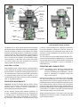
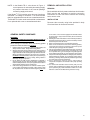
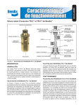
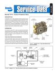
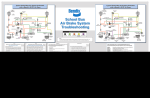
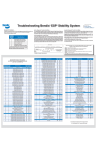
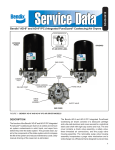
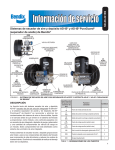
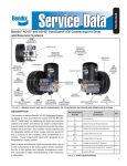
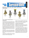
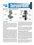
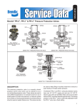
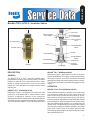
SD-03-4650
Bendix® TR-2™ & TR-3™ Inversion Valves
SUPPLY PORT
CAP NUT
SEAL RING
INLET & EXHAUST
VALVE SPRING
MOUNTING NUT
& LOCKWASHER
INLET & EXHAUST
VALVE
DELIVERY PORT (2)
BODY
PISTON GROMMET
(SMALL)
CONTROL PORT (3)
PISTON
PISTON SPRINGS
PISTON GROMMET
(LARGE)
RETAINER RING
EXHAUST
COVER PLATE
EXHAUST
DIAPHRAGM
DIAPHRAGM WASHER
CAP SCREW
FIGURE 1 - BENDIX® TR-2™ INVERSION VALVE
DESCRIPTION
GENERAL
BENDIX® TR-3™ INVERSION VALVE
Referring to Figure 2, the Bendix TR-3 valve is similar in
function to the Bendix TR-2 valve, but with a die cast body.
Referring to Figure 3, some TR-3 valves have an internal
passage in the body connecting supply pressure to control.
The external control port is permanently plugged in such
valves.
The Bendix® TR-2™ & TR-3™ valves are normally open,
pilot-operated, inverting, on-off, two-way valves. As control
pressure is reduced—to the point that the piston return
spring or springs overcomes the force on the control
piston—the valve will deliver full supply pressure at the
delivery port.
OPERATION
BENDIX® TR-2™ INVERSION VALVE
BENDIX TR-2 & TR-3 INVERSION VALVES
Referring to Figure 1, the Bendix TR-2 valve was used
primarily in early Bendix® DD-3™ safety actuator control
systems. It applied air pressure to the emergency
diaphragm of the DD-3 actuators from a protected reservoir
as control pressure is released from the lock mechanism.
The TR-2 valve is available in 1-1/4" bulk head-mount only.
When sufficient air pressure is present in the control cavity
to overcome the setting of the piston return spring, the
piston is held away from the inlet valve which is, in turn,
held closed by the inlet valve return spring. The delivery
lines are vented to atmosphere through the hollow exhaust
stem of the piston. When air pressure in the control cavity
falls to a predetermined pressure—or is vented from the
control cavity—the piston spring forces the piston against
the inlet valve, closing the exhaust passage in the hollow
piston stem. Further travel of the piston opens the inlet
valve allowing the passage of air past the open inlet valve,
and out the delivery port.
1
1/4” P.T. SUPPLY
O-RING
INTERNAL
PASSAGE
CAP
VALVE
SPRING
VALVE STOP
INLET &
EXHAUST
VALVE
1/8” P.T.
CONTROL
1/4” P.T.
DELIVERY
O-RING
SHIM
PISTON
O-RING
DIAPHRAGM
RETAINER
EXHAUST
NUT
DIAPHRAGM
PISTON SPRING
EXHAUST
FIGURE 2 - BENDIX® TR-3™ INVERSION VALVE
The Bendix® TR-3™ valve, with the internal control passage
functions the same as described in the previous paragraph.
The only exception is that the control pressure is always
the same as the supply pressure. Consequently, as supply
pressure builds up, when the pressure is great enough to
overcome the piston return spring, the delivery pressure
will be vented out the exhaust. On descending supply/
control pressure, as the piston return spring overcomes
the control pressure the valve will deliver the remaining
supply pressure at the delivery port.
MOUNTING LOCATION
Care should be given to assure proper mounting location
of the valve with the exhaust pointed downward (toward
the road surface). It should be mounted high on the frame
rail, and away from road spray and debris. Unprotected
or exposed exhaust ports can allow migration of road
contaminants into the valve, which may cause accelerated
wear or unintended operation.
PREVENTIVE MAINTENANCE
Important: Review the Bendix Warranty Policy before
performing any intrusive maintenance procedures. A
warranty may be voided if intrusive maintenance is
performed during the warranty period.
No two vehicles operate under identical conditions, as
a result, maintenance intervals may vary. Experience is
a valuable guide in determining the best maintenance
interval for air brake system components. At a minimum,
the inversion valves should be inspected every six(6)
2
FIGURE 3 - BENDIX® TR-3™ INVERSION
VALVE INTERNAL BLEED CONTROL
months or 1500 operating hours, whichever comes first,
for proper operation. Should the inversion valves not
meet the elements of the operational tests noted in this
document, further investigation and service of the valve
may be required.
The TR-3 valve is non-serviceable while the Bendix® TR-2™
valve can be serviced with a maintenance kit. For the latest
service parts and kits, refer to the Bendix Quick Reference
Catalog (BW1114) available for order or download at
www.bendix.com
OPERATING AND LEAKAGE TESTS
NOTE: The following checks should be made with two
calibrated gauges or two gauges known to be
accurate. Depending upon installation, it may be
easier or necessary to completely remove the
valve to test properly.
Install one test gauge in a common control and supply
line; install the other gauge in the delivery port. Gradually
apply pressure to the common supply and control line. On
ascending pressure, note at what pressure exhaust occurs
and compare with the vehicle manual. With air pressure
present in supply and control ports, apply a soap solution to
the delivery and exhaust ports. Leakage should not exceed
100 SCCM or a 1" bubble in 5 seconds. Excessive leakage
would indicate a faulty o-ring or inlet valve.
Slowly decrease pressure in the control cavity and note
at what pressure delivery is made. Compare this with the
vehicle manual notation.
NOTE: In the Bendix® TR-3™ valve shown in Figure 3,
control pressure is reduced by decreasing supply
air pressure because of the internal passage
connecting supply and control.
®
If the Bendix TR-3 inversion valve does not function as
described—or leakage is excessive—it is recommended
that it be replaced with a new valve or remanufactured unit.
The Bendix TR-2 valve can be serviced with a maintenance
kit or replaced with a new or remanufactured valve.
REMOVAL AND INSTALLATION
REMOVAL
Block and hold vehicle by means other than the air brakes.
Drain service and emergency or parking reservoirs.
Disconnect air lines from valve. Remove the mounting
bolts, remove valve.
INSTALLATION
Remount valve securely using holes provided in body.
Check and clean air lines and reconnect.
GENERAL SAFETY GUIDELINES
WARNING!
PLEASE READ AND FOLLOW THESE INSTRUCTIONS TO
AVOID PERSONAL INJURY OR DEATH:
5.
When working on or around a vehicle, the following general
precautions should be observed at all times.
6.
7.
1. Park the vehicle on a level surface, apply the parking brakes, and
always block the wheels. Always wear safety glasses.
2. Stop the engine and remove ignition key when working under or
around the vehicle. When working in the engine compartment, the
engine should be shut off and the ignition key should be removed.
Where circumstances require that the engine be in operation,
EXTREME CAUTION should be used to prevent personal injury
resulting from contact with moving, rotating, leaking, heated or
electrically charged components.
3. Do not attempt to install, remove, disassemble or assemble a
component until you have read and thoroughly understand the
recommended procedures. Use only the proper tools and observe
all precautions pertaining to use of those tools.
4. If the work is being performed on the vehicle’s air brake system,
or any auxiliary pressurized air systems, make certain to drain
the air pressure from all reservoirs before beginning ANY work
8.
9.
10.
11.
on the vehicle. If the vehicle is equipped with a Bendix® AD-IS®
air dryer system or a dryer reservoir module, be sure to drain the
purge reservoir.
Following the vehicle manufacturer’s recommended procedures,
deactivate the electrical system in a manner that safely removes
all electrical power from the vehicle.
Never exceed manufacturer’s recommended pressures.
Never connect or disconnect a hose or line containing pressure;
it may whip. Never remove a component or plug unless you are
certain all system pressure has been depleted.
Use only genuine Bendix® brand replacement parts, components
and kits. Replacement hardware, tubing, hose, fittings, etc. must
be of equivalent size, type and strength as original equipment
and be designed specifically for such applications and systems.
Components with stripped threads or damaged parts should be
replaced rather than repaired. Do not attempt repairs requiring
machining or welding unless specifically stated and approved by
the vehicle and component manufacturer.
Prior to returning the vehicle to service, make certain all
components and systems are restored to their proper operating
condition.
For vehicles with Automatic Traction Control (ATC), the ATC
function must be disabled (ATC indicator lamp should be ON)
prior to performing any vehicle maintenance where one or more
wheels on a drive axle are lifted off the ground and moving.
3
BW1581 © 2011 Bendix Commercial Vehicle Systems Company LLC, a member of the Knorr-Bremse Group • 8/2011 • All Rights Reserved.
4