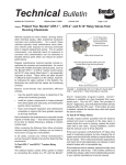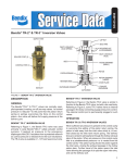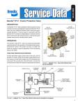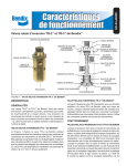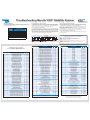
1
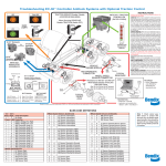
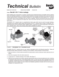
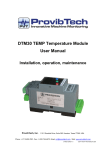
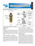
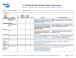
Troubleshooting Bendix ESP Stability System
®
DIAGNOSTIC MODES
In order to communicate with the ECU, the controller has several modes that the technician can
select, allowing information to be retrieved, or other ECU functions to be accessed.
To enter the various diagnostic modes:
No. of Times
to Press the
Blink Code
Switch
Active diagnostic trouble code retrieval
2
Inactive diagnostic trouble code retrieval
3
Clear active diagnostic trouble codes
4
System configuration check
Active Diagnostic Trouble Code Mode
For troubleshooting, typically the Active and Inactive Diagnostic Trouble Retrieval Modes are
used. The technician presses the blink code switch once and the ABS indicator lamp flashes
a first group of two codes, and if there are more trouble codes recorded, this is followed by a
second set of codes, etc. (See this page for a brief directory of these codes.)
Clearing Diagnostic Trouble Codes
To clear active diagnostic trouble codes (as problems are fixed), simply clear (or “self-heal”) by
removing and re-applying ignition power. The only exception is for wheel speed sensor trouble
codes, which clear when power is removed, re-applied, and the ECU detects valid wheel speed
from all wheel speed sensors. Alternately, codes may be cleared by pressing the diagnostic
blink code switch 3 times (to enter the Clear Active Diagnostic Trouble Code Mode) or by using
a hand-held or PC-based diagnostic tool. Hand-held or PC-based diagnostic tools are able to
clear wheel speed sensor trouble codes without the vehicle being driven.
System Mode Entered
1
®
5
Dynamometer Test Mode
7*
Reconfigure ECU (See SD sheet for details.)
BW1114 Quick Reference Catalog
BW1231 Tractor & Truck Air Brake System Troubleshooting Wallchart
BW1396 Tractor & Truck Air Brake System Troubleshooting
BW1555 Brake Balance Procedure
BW2780 Troubleshooting Bendix® ESP® Stability System Wallchart version of this piece
BW5057 Air Brake Handbook
SD-13-4869 Service Data Sheet for EC-60™ ABS/ATC Advanced Controllers
EXAMPLE OF BLINK CODE MESSAGE
Bendix Blink Code to Description
and Other Electronic Messaging Standards
(J1587 SID, J1939 SPN & FMI)
2
3
4
5
14
15
2
3
4
5
14
15
2
3
4
5
14
15
2
3
4
5
14
15
2
3
4
5
14
15
2
3
4
5
14
15
2
3
4
5
14
15
2
3
4
5
14
15
14
15
1
1
1
1
1
1
2
2
2
2
2
2
3
3
3
3
3
3
4
4
4
4
4
4
5
5
5
5
5
5
6
6
6
6
6
6
7
7
7
7
7
7
8
8
8
8
8
8
10
10
6
6
6
6
6
6
6
6
6
1
2
3
4
5
6
7
8
9
7
8
9
10
16
17
20
7
8
9
1
1
1
1
1
1
1
2
2
2
DTC Description
No DTCs
Wheel Speed Sensor DTCs
SA Left WSS Excessive Air Gap
SA Right WSS Excessive Air Gap
DA Left WSS Excessive Air Gap
DA Right WSS Excessive Air Gap
AA Left WSS Excessive Air Gap
AA Right WSS Excessive Air Gap
SA Left WSS Output Low @ Drive-Off
SA Right WSS Output Low @ Drive-Off
DA Left WSS Output Low @ Drive-Off
DA Right WSS Output Low @ Drive-Off
AA Left WSS Output Low @ Drive-Off
AA Right WSS Output Low @ Drive-Off
SA Left WSS Open or Shorted
SA Right WSS Open or Shorted
DA Left WSS Open or Shorted
DA Right WSS Open or Shorted
AA Left WSS Open or Shorted
AA Right WSS Open or Shorted
SA Left WSS Loss of Sensor Signal
SA Right WSS Loss of Sensor Signal
DA Left WSS Loss of Sensor Signal
DA Right WSS Loss of Sensor Signal
AA Left WSS Loss of Sensor Signal
AA Right WSS Loss of Sensor Signal
SA Left WSS Wheel End
SA Right WSS Wheel End
DA Left WSS Wheel End
DA Right WSS Wheel End
AA Left WSS Wheel End
AA Right WSS Wheel End
SA Left WSS Erratic Sensor Signal
SA Right WSS Erratic Sensor Signal
DA Left WSS Erratic Sensor Signal
DA Right WSS Erratic Sensor Signal
AA Left WSS Erratic Sensor Signal
AA Right WSS Erratic Sensor Signal
SA Left WSS Tire Size Calibration
SA Right WSS Tire Size Calibration
DA Left WSS Tire Size Calibration
DA Right WSS Tire Size Calibration
AA Left WSS Tire Size Calibration
AA Right WSS Tire Size Calibration
SA Left Poor Brake Performance
SA Right Poor Brake Performance
DA Left Poor Brake Performance
DA Right Poor Brake Performance
AA Left Poor Brake Performance
AA Right Poor Brake Performance
AA Left WSS Configuration Error
AA Right WSS Configuration Error
Power Supply DTCs
Battery Voltage Too Low
Battery Voltage Too High
Battery Voltage Too Low During ABS
Battery Voltage Input Open Circuit
Ignition Voltage Too Low
Ignition Voltage Too High
Ignition Voltage Too Low During ABS
Input Voltage Excessive Noise (Temp.)
Input Voltage Excessive Noise (Latched)
Pressure Modulator Valve DTCs
SA Left PMV REL Solenoid Shorted to Ground
SA Right PMV REL Solenoid Shorted to Ground
DA Left PMV REL Solenoid Shorted to Ground
DA Right PMV REL Solenoid Shorted to Ground
AA Left PMV REL Solenoid Shorted to Ground
AA Right PMV REL Solenoid Shorted to Ground
Trailer PMV REL Solenoid Shorted to Ground
SA Left PMV REL Solenoid Shorted to Voltage
SA Right PMV REL Solenoid Shorted to Voltage
DA Left PMV REL Solenoid Shorted to Voltage
Clearing Active Diagnostic Trouble Codes
The ECU will clear active trouble codes when the diagnostic blink code switch is depressed
and released three times.
Visit www.bendix.com or www.foundationbrakes.com for Service Data
Sheets and other literature such as the following:
* To enter the Reconfiguration Mode, the switch must be held in
before the application of ignition power. Once the power is supplied,
the switch is released and then pressed seven times.
Bendix Blink Code
1st digit 2nd digit
1
1
Inactive Diagnostic Trouble Code Mode
The ECU stores past trouble codes and comments (such as configuration changes) in its memory.
This record is commonly referred to as “event history.” When an active trouble code is cleared,
the ECU stores it in the event history memory as an inactive trouble code.
Using blink codes, the technician may review all inactive trouble codes stored on the ECU. The
ABS indicator lamp will display inactive diagnostic blink codes when the diagnostic blink code
switch is depressed and released two times.
Inactive trouble codes, and event history, may be retrieved and cleared by using a hand-held or
PC-based diagnostic tool, such as the Bendix® ACom™ Diagnostics software.
J1587 J1939
FMI
SID
SPN
N/A
N/A
1
2
3
4
5
6
1
2
3
4
5
6
1
2
3
4
5
6
1
2
3
4
5
6
1
2
3
4
5
6
1
2
3
4
5
6
1
2
3
4
5
6
82
83
84
85
86
87
5
6
789
790
791
792
793
794
789
790
791
792
793
794
789
790
791
792
793
794
789
790
791
792
793
794
789
790
791
792
793
794
789
790
791
792
793
794
789
790
791
792
793
794
3534
3535
3536
3537
3538
3539
793
794
1
1
1
1
1
1
14
14
14
14
14
14
2
2
2
2
2
2
10
10
10
10
10
10
7
7
7
7
7
7
8
8
8
8
8
8
13
13
13
13
13
13
7
7
7
7
7
7
13
13
251
251
251
251
251
251
251
251
251
627
627
627
627
627
627
627
627
627
4
3
4
5
4
3
4
2
14
48
49
50
51
52
53
66
48
49
50
795
796
797
798
799
800
1056
795
796
797
4
4
4
4
4
4
4
3
3
3
Bendix Blink Code
1st digit 2nd digit
10
2
16
2
17
2
20
2
7
3
8
3
9
3
10
3
16
3
17
3
20
3
7
4
8
4
9
4
10
4
16
4
17
4
20
4
7
5
8
5
9
5
10
5
16
5
17
5
20
5
7
6
8
6
9
6
10
6
16
6
17
6
20
6
7
7
8
7
9
7
10
7
16
7
17
7
20
7
7
8
8
8
9
8
10
8
16
8
17
8
20
8
11
11
11
11
11
11
1
2
3
4
5
6
11
7
11
12
12
12
12
1
2
3
12
4
12
5
12
12
12
12
12
12
6
7
8
9
10
11
12
12
12
12
12
12
12
12
12
13
14
15-21
22
23
24
25
13
13
1
2
DTC Description
DA Right PMV REL Solenoid Shorted to Voltage
AA Left PMV REL Solenoid Shorted to Voltage
AA Right PMV REL Solenoid Shorted to Voltage
Trailer PMV REL Solenoid Shorted to Voltage
SA Left PMV REL Solenoid Open Circuit
SA Right PMV REL Solenoid Open Circuit
DA Left PMV REL Solenoid Open Circuit
DA Right PMV REL Solenoid Open Circuit
AA Left PMV REL Solenoid Open Circuit
AA Right PMV REL Solenoid Open Circuit
Trailer PMV REL Solenoid Open Circuit
SA Left PMV HLD Solenoid Shorted to Ground
SA Right PMV HLD Solenoid Shorted to Ground
DA Left PMV HLD Solenoid Shorted to Ground
DA Right PMV HLD Solenoid Shorted to Ground
AA Left PMV HLD Solenoid Shorted to Ground
AA Right PMV HLD Solenoid Shorted to Ground
Trailer PMV HLD Solenoid Shorted to Ground
SA Left PMV HLD Solenoid Shorted to Voltage
SA Right PMV HLD Solenoid Shorted to Voltage
DA Left PMV HLD Solenoid Shorted to Voltage
DA Right PMV HLD Solenoid Shorted to Voltage
AA Left PMV HLD Solenoid Shorted to Voltage
AA Right PMV HLD Solenoid Shorted to Voltage
Trailer PMV HLD Solenoid Shorted to Voltage
SA Left PMV HLD Solenoid Open Circuit
SA Right PMV HLD Solenoid Open Circuit
DA Left PMV HLD Solenoid Open Circuit
DA Right PMV HLD Solenoid Open Circuit
AA Left PMV HLD Solenoid Open Circuit
AA Right PMV HLD Solenoid Open Circuit
Trailer PMV HLD Solenoid Open Circuit
SA Left PMV CMN Open Circuit
SA Right PMV CMN Open Circuit
DA Left PMV CMN Open Circuit
DA Right PMV CMN Open Circuit
AA Left PMV CMN Open Circuit
AA Right PMV CMN Open Circuit
Trailer PMV CMN Open Circuit
SA Left PMV Configuration Error
SA Right PMV Configuration Error
DA Left PMV Configuration Error
DA Right PMV Configuration Error
AA Left PMV Configuration Error
AA Right PMV Configuration Error
Trailer PMV Chuff Test/Configuration Error
J1939 DTCs
J1939 Serial Link
J1939 Retarder
J1939 Engine Communications
J1939 Invalid Data (Engine/Retarder)
J1939 Supply Pressure
J1939 ESP Messages Invalid Data
Miscellaneous DTCs
Time-Out or Invalid Data on ETC7/VP15 (for
HSA-Function)
J1939 HSA Switch Error or Unavailable
Stop Lamp Switch Not Detected
Stop Lamp Switch Always On
Dynamometer Test Mode
Retarder Relay or HSA Lamp Open Circuit or
Shorted to Ground
Retarder Relay Circuit or HSA Lamp Shorted to
Voltage
ABS Dash Indicator Circuit DTC
PMV Common Shorted to Ground
PMV Common Shorted to Voltage
ATC Disabled to Prevent Brake Fade
Tire Size Out of Range (Front to Rear)
Wheel Speed Sensors Reversed on an Axle
Diff Lock Solenoid Shorted to Ground or Open
Circuit
Diff Lock Solenoid Shorted to Voltage
Sensor CAN Supply Voltage Error
Reserved
ESP Sensor Voltage Out of Range
I/O2 or I/O3 Shorted High
HSA Solenoid Shorted to Voltage
HSA Solenoid Open or Shorted to Ground
ECU DTCs
ECU (02)
ECU (10)
J1587
SID
51
52
53
66
48
49
50
51
52
53
66
42
43
44
45
46
47
66
42
43
44
45
46
47
66
42
43
44
45
46
47
66
7
8
9
10
11
12
66
7
8
9
10
11
12
66
J1939
SPN
798
799
800
1056
795
796
797
798
799
800
1056
795
796
797
798
799
800
1056
795
796
797
798
799
800
1056
795
796
797
798
799
800
1056
795
796
797
798
799
800
1056
795
796
797
798
799
800
1056
231
231
231
231
231
231
639
639
639
639
639
639
FMI
3
3
3
3
5
5
5
5
5
5
5
4
4
4
4
4
4
4
3
3
3
3
3
3
3
5
5
5
5
5
5
5
5
5
5
5
5
5
5
13
13
13
13
13
13
7
12
14
2
2
2
2
231
639
2
231
55
231
17
639
1045
639
576
2
7
2
14
13
801
2
13
801
3
23
93
93
17
79
22
811
802
802
614
1069
810
2
4
3
14
13
7
102
564
5
102
103
N/A
103
154
94
94
564
3
1808 2
N/A N/A
1808 2
614
3
2622 3
2622 5
254
254
629
629
Bendix Blink Code
1st digit 2nd digit
13
3
13
4
13
5
13
6
13
7
13
8
13
9
13
10
13
11
13
12
13
13
13
14
13
15
13
16
13
17
13
18
13
19
13
20
13
21
13
22
13
23
13
24
13
25
18
18
18
18
19
19
19
19
1
2
3
4
1
2
3
4
21
21
21
21
21
21
21
21
21
21
1
2
3
4
5
6
7
8
9
10
22
22
22
22
22
22
22
22
22
22
22
22
1
2
3
4
5
6
7
8
9
10
11
12
22
13
22
14
22
22
15
16
23
23
23
23
23
1
2
3
4
5
23
6
23
7
24
24
24
24
24
24
1
2
3
4
5
6
DTC Description
ECU (11)
ECU (12)
ECU (13)
ECU (14)
ECU (15)
ECU (16)
ECU (17)
ECU (18)
ECU (1A)
ECU (1B)
ECU (80)
ECU (04)
ECU (06)
ECU (0E)
ECU (0D)
ECU (19)
ECU (1C)
ECU (27)
ECU (1D)
ECU (1E)
ECU (28)
ECU (37)
VIN / Chassis Mis-Match
TCV DTCs
TCV DA Solenoid Shorted to Ground
TCV DA Solenoid Shorted to Voltage
TCV DA Solenoid Open Circuit
TCV DA Configuration Error
TCV SA Solenoid Shorted to Ground
TCV SA Solenoid Shorted to Voltage
TCV SA Solenoid Open Circuit
TCV SA Configuration Error
Steering Angle Sensor DTCs
SAS Not Calibrated
SAS Calibration in Progress
SAS Static Signal
SAS Signal Out of Range
SAS Signal Reversed
SAS Invalid Signal
SAS Gradient Error
SAS CAN Timeout
SAS Long Term Calibration Error
SAS Plausibility Check (Ref Yaw Rate)
Yaw Rate Sensor DTCs
YRS Signal Out of Range
YRS Sensor Reversed Signal
YRS Invalid Signal
YRS Gradient Error
YRS CAN Timeout
YRS Static BITE Error
YRS Dynamic BITE Error
YRS Fast Calibration Error
YRS Static Calibration Error
YRS Normal Calibration Error
YRS Sensitivity Calibration Error
YRS Plausibility Check (Ref Yaw Rate)
YRS Plausibility Error (Inside Model Based
Limits)
YRS Plausibility Error (Outside Model Based
Limits)
YRS Sign Check Not Completed
YRS Vibration Detected
Lateral Acceleration Sensor DTCs
LAS Signal Out of Range
LAS Calibration in Progress
LAS Static Calibration Error
LAS Long Term Calibration Error
LAS Plausibility Error (Inside Model Based Limits)
LAS Plausibility Error (Outside Model Based
Limits)
Erratic ESP Sensor Signal
Pressure Sensor DTCs
PS1 Open or Shorted
PS2 Open or Shorted
PS3 Open or Shorted
PS1/PS2 Plausibility Error
PS Supply Voltage Error
PS Not Calibrated
J1587 J1939
FMI
SID
SPN
254
629 12
254
629
2
254
629
2
254
629 12
254
629
2
254
630 13
254
630 13
254
630 12
254
802 12
254
802 12
254
629 12
254
629 12
254
629 12
254
629 12
254
629
2
254
629
2
253
630 12
253
630 12
253
630 13
253
630 13
253
630 13
254
629 12
254
629 12
18
18
18
18
19
19
19
19
806
806
806
806
807
807
807
807
4
3
5
13
4
3
5
13
89
89
89
89
89
89
89
89
89
89
1807
1807
1807
1807
1807
1807
1807
1807
1807
1807
13
13
2
2
2
12
2
9
2
2
103
103
103
103
103
103
103
103
103
103
103
103
1808
1808
1808
1808
1808
1808
1808
1808
1808
1808
1808
1808
2
2
2
2
9
2
2
2
2
2
2
2
103
1808
2
103
1808
2
89
103
1808
1808
13
2
99
99
99
99
99
1809
1809
1809
1809
1809
2
13
2
2
2
99
1809
2
99
1809
14
77
78
69
77
77
77
1067
1068
1059
1067
1067
1067
2
2
2
11
2
7
12
12
See the Service Data sheet for full test and repair procedures:
SD-13-4869 Bendix® EC-60™ Advanced ABS Controllers
Troubleshooting Bendix
ESP Stability System
®
®
Typical Tractor System Schematic with ESP® Stability
PP-5™ Control
Valve
TP-3DC™
Tractor
Protection
Valve
MV-3®
Control Valve
Typical Truck System Schematic with ESP® Stability
Control
WS-24™ Wheel
Speed Sensor
C
WS-24™ Wheel
Speed Sensor
S
WS-24™ Wheel
Speed Sensor
Hose
Couplings
Stop Light Switch
ADB-22X™
Disc Brake
M-32™ / M-32QR™
Modulator
DC-4® Double
Check Valve
EC-60™
Electronic
Controller
Advanced
ADB-22X™
Disc
Brake
Supply
ADB-22X™
Disc Brake
M-32™ /
M-32QR™
Modulator
(4 places)
TCS-9000™
Valve
M-32™ /
M-32QR™
Modulator
(4 places)
Antilock
Traction
Relay
Valve
E-8P® / E-6®
Brake Valve with
BVA-85™ Brake
Valve Actuator
SAS-60™
Steering
Angle
Sensor
AD-IS®
Air Dryer
Rear Axle
Module (RAM)
with ATR-6™
Traction
Relay Valve
YAS-60™ Yaw
Rate & Lateral
Acceleration
Sensor
PP-DC® Park
Control Valve
YAS-60™ Yaw
Rate & Lateral
Acceleration
Sensor
SAS-60™
Steering Angle
Sensor
Antilock
Traction
Relay
Valve
Orifice Check
Valve
To Accessories
PR-3™/
PR-4™
Valve
AD-9®/
AD-IP®
Air Dryer
Low Pressure
Indicator
Safety
Valve
Front
Axle Reservoir
Supply
Reservoir
®
ES™ Drum Brake w/
ASA-5® Automatic
Slack Adjuster and
Service Chamber
Tu-Flo 550/
Tu-Flo® 750
BA-921® / BA-922®
Air Compressor
Rear
Axle Reservoir
To Accessories
WS-24™ Wheel
Speed Sensor
ES™ Drum Brake w/
ASA-5® Automatic Slack
Adjuster and SB-4™
Spring Brake Chamber
ES™ Drum Brake w/
ASA-5® Automatic
Slack Adjuster and
Service Chamber
Primary
Secondary
Park
(Supply)
Antilock
Traction
Relay Valve
SR-7®
Spring Brake
Modulating
Valve
Low
Pressure
Indicator
Front
Axle Reservoir
Rear
Axle Reservoir
WS-24™ Wheel
Speed Sensor
ES™ Drum Brake w/
ASA-5® Automatic Slack
Adjuster and SB-4™
Spring Brake Chamber
Tu-Flo® 550/Tu-Flo® 750/
BA-921®/ BA-922®
Air Compressor
Notes:
The color coding of the brake system schematic follows TMC Recommended Practice
#423.
Air disc & drum brake actuation combined on a single axle are shown for pictorial
purposes only.
TRUCKS AND TRUCK TRACTORS:
Charging
ADB-22X™
Disc
Brake
E-8P®/ E-6®
Brake Valve
Stop
Light
Switch
QR-1C®
Quick
Release
Valve
EC-60™
Electronic
Controller
Advanced
Parking Accessories
(Control)
Troubleshooting: PC-based Troubleshooting, Blink Codes and Diagnostic Tools & Modes
The information presented here is condensed from the troubleshooting section of the Bendix® EC-60™ Advanced ABS Controller Service Data Sheet, SD-13-4869 available for download on www.bendix.com. Whenever possible, use a PC-based diagnostic tool, such as the Bendix®
ACom™ Software (free download from www.bendix.com) or hand-held Bendix® Remote Diagnostic Unit (RDU). The Bendix® ACom™ Software uses on-screen troubleshooting steps to help correct any DTCs. The Bendix® ACom™ Software (BW2329) may also be ordered on CD from the
Literature Center at www.bendix.com.
Below: Bendix® Remote
Diagnostic Unit (RDU),
Right: Bendix® ACom™
Diagnostics Software for
ABS
BLINK CODES
Blink codes allow a technician to troubleshoot ABS problems in situations where a hand-held
or PC-based diagnostic tool is not available. Instead, information about the ABS system is
communicated by the ECU, using the ABS indicator lamp to display sequences of blinks.
Note: The ECU will not enter the diagnostic blink code mode if the wheel speed sensors show
that the vehicle is in motion. If the ECU is in the diagnostic blink code mode and then detects
vehicle motion, it will exit the blink code mode.
In addition, by operating the blink code switch as described below, one of several diagnostic
modes can be entered. See Diagnostic Modes section below.
Blink Code Switch Activation
When activating the blink code switch:
ECU DIAGNOSTICS
The EC-60™ controller contains self-testing diagnostic circuitry that continuously checks for the
normal operation of internal components and circuitry, as well as external ABS components
and wiring.
Active Diagnostic Trouble Codes (DTCs)
When an erroneous system condition is detected, the EC-60™ controller:
1. Illuminates the appropriate indicator lamp(s) and disengages part or all of the ABS, ATC
and ESP functions. (See Service Data Sheet.)
2. Places the appropriate trouble code information in the ECU memory.
3. Communicates the appropriate trouble code information over the serial communications
diagnostic link as required. Hand-held or PC-based diagnostic tools attach to the vehicle
diagnostic connector, typically located on or under the dash.
When using our PC-based Bendix® ACom™ Software, follow the on-screen troubleshooting
steps to correct any DTCs. A hand-held tool such as the Bendix Remote Diagnostic Unit (RDU)
provides direct access to the DTCs without the need to use blink codes.
1. Wait at least two seconds after “ignition on.” (Except when entering Reconfiguration Mode
- see Service Data sheet.)
2. For the ECU to recognize that the switch is activated “on,” the technician must press for at
least 0.1 seconds, but less than 5 seconds. (If the switch is held for more than 5 seconds,
the ECU will register a malfunctioning switch.)
3. Pauses between pressing the switch when a sequence is required, (e.g. when changing
mode) must not be longer than 2 seconds.
4. After a pause of 3.5 seconds, the ECU will begin responding with output information blinks.
Blink Code Timing
The ECU responds with a sequence of blink codes. The overall blink code response from the
ECU is called a “message.” Each message includes, depending on the mode selected by the
technician, a sequence of one or more groups of blinks. Simply record the number of blinks for
each sequence and then use the brief troubleshooting index shown here, or full troubleshooting
information in the Service Data sheet, for active or inactive trouble codes.
NOTE:
1. Sequences of blinks illuminate the ABS indicator lamp for half a second, with half-second
pauses between them.
2. Pauses between blink code digits are 1.5 seconds.
3. Pauses between blink code messages are 2.5 seconds.
4. The lamp remains on for 5 seconds at the end of the messages.
Once the ABS indicator lamp begins displaying a sequence of codes, it continues until all blink
code messages have been displayed and then returns to the normal operating mode. During
this time, the ECU will ignore any additional blink code switch activation.
All trouble codes, with the exception of voltage and J1939 trouble codes, will remain in an active
state for the remainder of the power cycle.
Voltage trouble codes will clear automatically when the voltage returns within the required limits.
All ABS functions will be re-engaged.
J1939 trouble codes will clear automatically when communications are re-established.
www.bendix.com
BW2786 © 2009 Bendix Commercial Vehicle Systems LLC, a member of the Knorr-Bremse Group • All Rights Reserved • 08/09 • Printed in U.S.A.
www.foundationbrakes.com