1
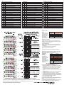
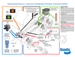
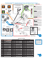
Troubleshooting EC-30™ Controller Antilock Systems with Optional Traction Control
ABS
TRACTION SERVICE Enable / Disable
(LOCATED IN DASH AREA)
Trailer ABS
ANTILOCK / TRACTION
CONTROLLER
(Ref. SD-13-4815)
When Servicing DRIVELINE
Disable TRACTION (Switch OFF)
DASH
LAMPS
Blink Code Switch
(Optional)
ATC
M-32™ Modulator
(Ref.
SD-13-4870)
EC-30™
CONTROLLER
DIAGNOSTIC
DISPLAY
M-32QR™
Modulator
M-30™
Modulator
Ty Wrap
(Ref. SD-13-4830)
ANTILOCK
MODULATOR
ASSEMBLIES
VEHICLE
ENGINE MODULE
Right
Angle
Mounting
Sensor
1587 DIAGNOSTIC
CONNECTOR
TYPICAL
REAR
AXLE
WHEEL SPEED
SENSOR-CONNECTOR
Lap Top
Toubleshooting Test
Source
B
Exhaust
A
Hold
C
M-32™ and M-32QR™
Modulator Twist-Lock (Bayonet)
and Threaded (Metric) Connectors
Source B
Connector
Exciter
Ring
Exhaust A
M-30™ and M-32™
Modulator Packard
Connector
M-30™ Modulator
M-32™ & M-32QR™
Modulators
Hold To Source:
C – B Read 3.5 to 5 Ohms Read 4.9 to 5.5 Ohms
Exhaust To Source: A – B Read 3.5 to 5 Ohms Read 4.9 to 5.5 Ohms
Exhaust To Hold: A – C Read 7.0 to 10 Ohms Read 9.8 to 11 Ohms
Source To Ground: B –
No Continuity
No Continuity
Computer
Parallel
or Serial
Cable
(Ref. SD-13-4754 for WS-20™sensors)
(Ref. SD-13-4860 for WS-24™sensors)
Straight
Sensor
Hold C
Resistance for WS-20™ and WS-24™
wheel speed sensors across pins:
1500-2500 Ohms
INSTRUCTIONS
ALWAYS USE EXTREME CAUTION WHEN WORKING ON
OR AROUND VEHICLES.
START UP: When power is applied the antilock and traction
dash warning lamps will illuminate for a period of 2.5 seconds
while the electronic control unit (ECU) is performing a self
check, and “Chuff” test. If a trailer being towed has PLC,
the trailer dash lamp will illuminate for 2.5 seconds then
turn off unless a fault is indicated. The ABS and traction
control modulators will be energized during the Chuff test.
It is recommended during the initial start up that the brakes
be applied to audibly hear the modulators exhaust during
the “Chuff’ test.
SERVICE NEEDED: When an issue is detected at start up,
the dash lights will flash and remain illuminated. When a
dynamic wheel speed issue is detected the dash lamps will
illuminate as early as 10 mph, indicating a wheel speed issue.
The dash lamps notify the driver that all or part of the ABS
function has been disengaged and standard air braking is
in effect. The ECU will automatically reset most intermittent
codes (self healing). In most instances, if the intermittent
code has occurred more than five times the issue will be
latched and require a magnetic reset. The area of concern
will always be identified in the diagnostic display.
TRACTION FUNCTION: The ECU monitors wheel spin.
When a spin condition exist, the traction dash lamp will
blink continuously indicating the traction control system
is active. IF SERVICING THE VEHICLE DRIVE LINE,
TRACTION SERVICE ENABLE / DISABLE SWITCH MUST
BE DISABLED.
(The traction dash lamp will be illuminated)
RESET: The ECU can be magnetically reset by momentarily
holding a magnet against the RESET area on the controller.
SELF CONFIGURING: During self configuring the ECU
will automatically determine the number of sensors and if
electronic engine equipped. The ECU will also determine if
the vehicle is traction equipped ONLY if the traction switch
is toggled prior to magnetically self configuring. Holding a
magnet against the RESET area for 30 seconds completes
self configuring.
BLINK CODE ACTIVATION: The ECU will provide blink
code diagnostics through the use of the blink code switch.
Details on active faults, fault history, ECU configuration, and
clearing of faults can be found in service data SD-13-4815.
Clip
TYPICAL
FRONT
AXLE
J1708/J1587
PC Software
• ACom® Diagnostics
order BW2329 or
download from
www.bendix.com
(RP-1210) Hardware
Interface Adapter
Hand Held Tools
• Brake-Link™* 5010749
• Application card available from
NEXIQ™*, SPX™*, Kent-Moore™*.
*Brake-Link and Nexiq are trademarks of NNT, Inc. SPX and Kent-Moore are trademarks of SPX Corporation.
BLINK CODE DEFINITIONS
1st 2nd
Digit Digit Fault Description
1
1
No Faults
Power / ABS Controller
1
2
Battery Voltage Too High
1
3
Battery Voltage Too Low
1
4
ABS Controller Fault (2)
1
5
ABS Controller Fault (6)
1
6
ABS Controller Fault (7)
1
7
ABS Controller Fault (9)
1
8
ABS Controller Fault (10)
1
9
ABS Controller Fault (11)
1
10
ABS Controller Fault (12)
1
11
ABS Controller Fault (13)
1
12
ABS Controller Fault (14)
1
13
ABS Controller Fault (1)
1
14
ABS Controller Fault (3)
1
15
ABS Controller Fault (8)
Wheel Speed Sensors
2
1
LF Sensor Start
3
1
RF Sensor Start
4
1
LR Sensor Start
5
1
RR Sensor Start
6
1
LM Sensor Start
7
1
RM Sensor Start
Wheel Speed Sensors (Continued)
2
2
LF Sensor Intermittent
3
2
RF Sensor Intermittent
4
2
LR Sensor Intermittent
5
2
RR Sensor Intermittent
6
2
LM Sensor Intermittent
7
2
RM Sensor Intermittent
2
3
4
5
6
7
3
3
3
3
3
3
LF Sensor Shorted to VBAT
RF Sensor Shorted to VBAT
LR Sensor Shorted to VBAT
RR Sensor Shorted to VBAT
LM Sensor Shorted to VBAT
RM Sensor Shorted to VBAT
2
3
4
5
6
7
4
4
4
4
4
4
LF Sensor Shorted to Ground
RF Sensor Shorted to Ground
LR Sensor Shorted to Ground
RR Sensor Shorted to Ground
LM Sensor Shorted to Ground
RM Sensor Shorted to Ground
2
3
4
5
5
5
LF Sensor Open
RF Sensor Open
LR Sensor Open
Wheel Speed Sensors (Continued)
5
5
RR Sensor Open
6
5
LM Sensor Open
7
5
RM Sensor Open
2
3
4
5
6
7
6
6
6
6
6
6
LF Sensor Shorted Across Sensor
RF Sensor Shorted Across Sensor
LR Sensor Shorted Across Sensor
RR Sensor Shorted Across Sensor
LM Sensor Shorted Across Sensor
RM Sensor Shorted Across Sensor
2
3
4
5
6
7
7
7
7
7
7
7
LF Sensor Lock Time Out
RF Sensor Lock Time Out
LR Sensor Lock Time Out
RR Sensor Lock Time Out
LM Sensor Lock Time Out
RM Sensor Lock Time Out
2
3
4
5
6
7
8
8
8
8
8
8
LF Sensor Frequency Doubling
RF Sensor Frequency Doubling
LR Sensor Frequency Doubling
RR Sensor Frequency Doubling
LM Sensor Frequency Doubling
RM Sensor Frequency Doubling
Note 1: Check sensor gap.
With sensor in contact with
the tone ring, for Bendix wheel
speed sensors, there should be
at least 0.25 vac voltage output
when turning wheel by hand at
0.5 rev/sec.
Wheel Speed Sensors (Continued)
2
9
LF Sensor High Frequency Noise
3
9
RF Sensor High Frequency Noise
4
9
LR Sensor High Frequency Noise
5
9
RR Sensor High Frequency Noise
6
9
LM Sensor High Frequency Noise
7
9
RM Sensor High Frequency Noise
2
3
4
5
6
7
10
10
10
10
10
10
LF Sensor Wobble Run
RF Sensor Wobble Run
LR Sensor Wobble Run
RR Sensor Wobble Run
LM Sensor Wobble Run
RM Sensor Wobble Run
4
5
6
7
11
11
11
11
LR Sensor Gross Mismatch
RR Sensor Gross Mismatch
LM Sensor Gross Mismatch
RM Sensor Gross Mismatch
2
3
4
5
6
7
12
12
12
12
12
12
LF Sensor Abnormal Speed
RF Sensor Abnormal Speed
LR Sensor Abnormal Speed
RR Sensor Abnormal Speed
LM Sensor Abnormal Speed
RM Sensor Abnormal Speed
ABS Modulators (Continued)
8
6
LF Modulator Shorted Between
8
12
RF Modulator Shorted Between
9
6
LR Modulator Shorted Between
9
12
RR Modulator Shorted Between
Retarder Relay Control
10
1
Retarder Relay Open
10
2
Retarder Relay Shorted
ATC - Traction Control
10
5
Traction Modulator Open
10
6
Traction Modulator Shorted to Ground
10
7
Traction Modulator Shorted
10
8
Traction Modulator Shorted to VBAT
Lamps
10
9
Traction Lamp Open
10
10
Traction Lamp Shorted
10
11
ABS - Warning Lamp Open
10
12
ABS - Warning Lamp Shorted
11
1
Trailer ABS - Warning Lamp Open (Dash Mounted)
11
2
Trailer ABS - Warning Lamp Shorted (Dash Mounted)
Engine Serial Communications
11
3
J1939 Data Link Retarder Communication Fault
11
4
J1939 Data Link Engine Communication Fault
11
5
J1922 Data Link Engine Communication Fault
11
6
J1922 Data Link Retarder Communication Fault
ABS Modulators
8
1
LF Modulator Lock Time Out
8
7
RF Modulator Lock Time Out
9
1
LR Modulator Lock Time Out
9
7
RR Modulator Lock Time Out
8
8
9
9
2
8
2
8
LF Modulator Open / Shorted to GND
RF Modulator Open / Shorted to GND
LR Modulator Open / Shorted to GND
RR Modulator Open / Shorted to GND
8
8
9
9
3
9
3
9
LF Modulator Shorted to Ground
RF Modulator Shorted to Ground
LR Modulator Shorted to Ground
RR Modulator Shorted to Ground
8
8
9
9
4
10
4
10
LF Modulator Shorted Solenoid
RF Modulator Shorted Solenoid
LR Modulator Shorted Solenoid
RR Modulator Shorted Solenoid
8
8
9
9
5
11
5
11
LF Modulator Shorted to VBAT
RF Modulator Shorted to VBAT
LR Modulator Shorted to VBAT
RR Modulator Shorted to VBAT
Display Active DTC
Codes
To display active DTC
codes, press the blink
code switch one time.
Following activation,
there will be a 3 second
delay followed by a
blink code display of all
active DTC codes.
Press the Blink
Code Switch
Blink Code Action
1 time
2 times
3 times
4 times
Display Active DTC Codes
Display DTC Code History
Reset Active DTC Codes
Display EC-30 Configuration
Display DTC Code History
To display history DTC codes, press the blink code switch two times.
Following activation, there will be a 3 second delay followed by a blink
code display of all history DTC codes.
M-30™ modulator
C1-D1 3.5-5.0 Ohms
C1-E1 3.5-5.0 Ohms
D1-E1 7.0-10.0 Ohms
™
M-30 modulator
H1-G1 3.5-5.0 Ohms
H1-F1 3.5-5.0 Ohms
G1-F1 7.0-10.0 Ohms
M-32™ modulator
4.9-5.5 Ohms
4.9-5.5 Ohms
9.8-11.0 Ohms
™
M-32 modulator
4.9-5.5 Ohms
4.9-5.5 Ohms
9.8-11.0 Ohms
Reset Active DTC Codes
To reset active DTC codes, press the blink code switch three times.
Following activation, there will be a 3 second delay followed by a blink
code message of:
1-1, (System Fully Operational - No DTCs Detected)
or,
A blink code display of all active DTC codes.
The ABS warning lamp will stay on if active DTCs are still present.
Resetting active DTCcodes with blink code diagnostics does not clear
information from DTC history. DTC history can be retrieved by using
blink code diagnostics or by using a diagnostic tool.
Display EC-30™
Controller
Configuration
To check the ECU
configuration, press the
blink code switch four
times. Following
activation, there will be
a 3 second delay
followed by a blink code
™
display of the EC-30
configuration.
M-30™ modulator
A1-B1 3.5-5.0 Ohms
A1-C1 3.5-5.0 Ohms
B1-C1 7.0-10.0 Ohms
M-32™ modulator
4.9-5.5 Ohms
4.9-5.5 Ohms
9.8-11.0 Ohms
M-30™ modulator
F1-E1 3.5-5.0 Ohms
F1-D1 3.5-5.0 Ohms
E1-D1 7.0-10.0 Ohms
M-32™ modulator
4.9-5.5 Ohms
4.9-5.5 Ohms
9.8-11.0 Ohms
Contacts above should have no continuity to ground, except contacts A1, A2, A3
of 30-pin connector. Contacts B1, K2, and K3 supply power to the EC-30™ controller connector
BW2175 © 2010 Bendix Commercial Vehicle Systems LLC • All Rights Reserved • Printed in U.S.A. 9/10
Products shown on this document may be covered by one or more of the following
Patents: 6254048, 6324468, 6209971, 4837552, 5341298, 5613744, 6237401.
1st Digit
2
3
2nd Digit
2
3rd Digit
2
3
4
5
Sensors
4 Sensors
6 Sensors
Modulators
4 Modulators
ATC
Not ATC
ATC Engine Torque Limiting Only
ATC Differential Brake Only
Full ATC (Engine Torque Limiting
and Differential Braking)
Most Commonly Encountered Problems
That Result In LED’s Being Illuminated
Repair or Replace Components as Necessary
1. Abraded or cut wires in the convoluted tubing near frame clamps.
2. Cut or corroded wires near sharp frame members and frame mounted
modulators.
3. Wire jacket worn through from overlapping sensor and modulator
wires near frame members and frame mounted modulators.
4. Corroded connectors and connections not properly sealed or damaged
seals.
5. Damaged connector latches or connectors not completely seated to
mating assemblies.
6. Terminals not completely latched or seated into connectors.
7. Excessive sensor air gap, sensor clip tension, or excessive bearing
end play (gently push sensor against wheel hub, or readjust bearings.)
8. Damage to exposed wires exiting or entering the convoluted tubing.
9. Worn, chipped or damaged sensor or modulator.
10. Non functioning antilock controller.
If Traction Dash Lamp Only Illuminated, Check/Repair These Items
First:
1. Traction enable/disable switch in wrong position.
2. Loss of traction engine serial communication (check service manual).
3. Traction solenoid not connected, or exceeds resistance range.