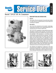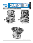
1
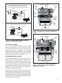
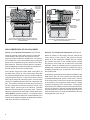
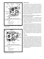
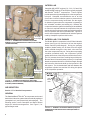
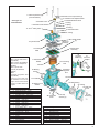
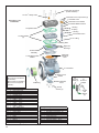
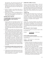
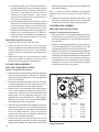
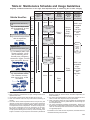
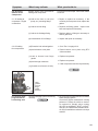
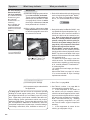
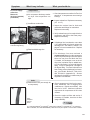
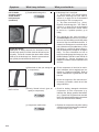
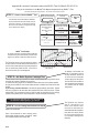
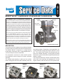
Section 2: Closed Room Compressor (refer to Figure 16)
Side View
1. Remove the discharge safety valve (12) from the
cylinder head (13).
2. To restrain the spring force exerted by balance piston
spring (8) of the unloader assembly, hold the unloader
cover (4) in place while removing the two unloader
cover cap screws (2). Carefully release the hold on the
unloader cover until the spring force is relaxed, then
remove the unloader cover.
3. Remove the unloader cover gasket (5).
4. Remove the balance piston (6), its spring (8) and the
unloader piston (10) along with its o-rings (7, 9 & 11)
from the cylinder head (13).
5. Remove the six hex head bolts from the cylinder head.
Note: The five hex bolts located towards the perimeter
of the cylinder head retain the cylinder head directly to
the crankcase. The single hex bolt in the center of the
cylinder head holds the cylinder head, cooling plate
and valve plate assembly together; independent of the
crankcase.
6. Gently tap the cylinder head, cooling plate (15) and
valve plate assembly (16) with a soft mallet to break
the gasket seal between the valve plate assembly and
the crankcase (21). Lift the cylinder head with cooling
plate and valve plate assembly off the crankcase.
7. Remove the metal inlet reed valve/gasket (17).
8. Gently tap the cylinder head, cooling plate and valve
plate assembly with a soft mallet to break the gasket
seals. Then separate the cylinder head from the cooling
plate (15) and valve plate assembly and remove the
two gaskets (14) between them.
Compressor
Oil Supply
Port
Pre-formed
Metal
Oil Supply
Tube
Lubricating
Oil outlet
Engine
Oil Supply
Line
Lubricating Oil
From the Engine
Enters Here
Crankcase Cover with
Oil Jet Assembly
FIGURE 17 – VIEWS OF SPECIAL CRANKCASE COVER
WITH OIL JET ASSEMBLY FOR CAT C11/C13 ENGINE
APPLICATIONS
NOTE: Mark position of the special crankcase cover. It
must be re-installed with the same orientation to assure
proper operation of the oil jet.
c. Remove the four crankcase cover cap screws
securing the special crankcase cover to the
crankcase. Using a soft mallet, gently tap the
crankcase cover to break the gasket seal. Remove
the crankcase cover gasket (27).
CRANKCASE COVER
REAR END COVER (If Present)
1. Remove the four crankcase cover cap screws (29)
securing the crankcase cover (28) to the crankcase
(21). Using a soft mallet, gently tap the crankcase cover
to break the gasket seal. Remove the crankcase cover
gasket (27).
1. Remove the four end cover cap screws (26) that secure
the rear end cover to the crankcase.
2. In the case of the Caterpillar C11 and C13 engine
application, the BA-921® standard compressor utilizes
an “oil jet” that sprays oil under the piston for purposes
of cooling. This oil jet is part of a special crankcase
cover that is used strictly on the BA-921® compressor for
the C11 and C13 engine installation (Figure 13). Refer
to section OPERATION – Lubrication for description
of the system. To disassemble, perform the following
steps. (Refer to Figure 17.)
CLEANING OF PARTS
a. Remove the oil supply line from the engine at the
inlet to the special crankcase cover.
b. Remove the metal oil supply tube at the compressor
oil supply port and at the outlet fitting of the special
crankcase cover.
14
2. Remove the rear end cover from the crankcase.
Remove the o-ring seal (24) from the end cover.
GENERAL
All parts should be cleaned in a good commercial grade of
solvent and dried prior to inspection.
CYLINDER HEAD ASSEMBLY
1. Carefully remove all gasket material adhering to the
cylinder head (13), cooling plate (15), valve plate
assembly (16) and cast iron crankcase (21). Make
certain not to scratch or mar the gasket surfaces.
Pay particular attention to the gasket surfaces of the
head.
2. Remove carbon deposits from the discharge and inlet
cavities of the cylinder head, cooling plate and valve