1
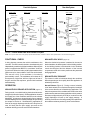
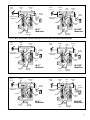
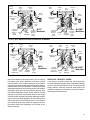
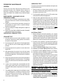
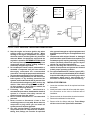
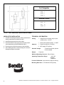
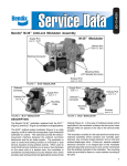
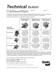
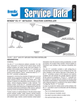
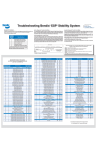
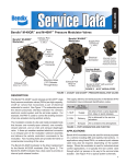
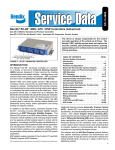
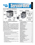
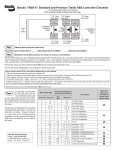
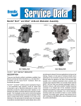
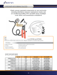
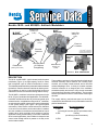
SD-13-4870
®
Bendix® M-32™ and M-32QR™ AntiLock Modulators
Delivery Port
™
M-32QR
Modulator*
(Casting has
2, DEL)
M-32™
Modulator
Supply Port
(Casting has
1, SUP)
Supply Port
(Casting has
1, SUP)
Electrical
Connector
Electrical
Connector
* All M-32QR™ modulators
except p/n 5011281 (Bluebird)
have the shorter exhaust port.
Previous
Model
M-30™
Modulator
Exhaust Port
(Casting has 3, EXH)
Mounting Holes
(.33" Diameter
Through Body)
Exhaust Port
(Casting has
3, EXH)
FIGURE 2: M-30™ MODULATOR
DESCRIPTION
The M-32™ and M-32QR™ (quick release) antilock system
modulators (Figure 1) are high capacity, on/off air valves
that incorporate a pair of electrical solenoids for control.
The solenoids provide the electro-pneumatic interface between
the antilock controller electronics and the air brake system.
The modulator is used to control the braking function on
individual or dual service actuators during antilock activity.
The M-32QR™ modulator is the direct replacement for the
M-30™ (Figure 2) modulator in all applications. The M-32QR™
modulator includes a bias valve to provide an internal quick
release function. In applications using an M-32™ modulator,
an external quick release valve may be required, depending
on the system design (see Figure 3 for typical system
schematics). When used to control both service chambers
on an axle or two chambers on the same side of a tandem
axle, the modulator is sometimes mounted ahead of a quick
release valve, which provides quick exhaust of service
applications during normal braking. In the case of individual
wheel control applications, the modulator is always the last
control valve through which air passes on its way to the
service brake actuator.
FIGURE 1: M-32™ AND M-32QR™ MODULATORS
The modulator consists of a die cast aluminum body and a
solenoid assembly which contains one normally open
solenoid, one normally closed solenoid, and an inlet and
exhaust diaphragm valve. A three pin, weather resistant
electrical connector is an integral part of the modulator
solenoid assembly and serves to carry control commands
from the antilock controller to the modulator. Two mounting
holes are provided for frame or cross member mounting of
the valve.
The supply, delivery and exhaust ports on the M-32™
modulator are identified with a cast, embossed numeral for
positive identification.
Identification
Air Line Connection
1, SUP
Supply
(incoming air from foot, relay or quick release valve)
2, DEL
Delivery
(air delivery to service actuators)
3, EXH
Exhaust
1
Front Axle Systems
Wheel Control
Rear Axle System
Wheel Control
Axle Control
Wheel Control
Service Brake
Chamber
To Antilock
Controller
To Antilock
Controller
M-32QR ™
Modulator
To Antilock
Controller
M-32 ™ or M-32QR™
Modulator
Controller/Relay
Assembly
or
or
M-32™ or M-32QR™
Modulator
Quick Release Valve
™
M-32QR
Modulator
M-32™ or M-32QR™
Modulator
To Antilock
Controller
To Antilock
Controller
Service Brake
Chamber
To Antilock
Controller
Service Brake
Chamber
Quick
Release
Valve
Service Brake
Chamber
M-32™ or
M-32QR ™
Modulator
M-32™ or M-32QR™
Modulator
To Antilock
Controller
Service &
Spring Brake
Chamber
FIGURE 3: TYPICAL WHEEL AND AXLE CONTROL SYSTEMS
NOTE: use of a quick release valve is not typically required with the M-32QR™ modulator. Refer to vehicle specifications for recommended configuration.
FUNCTIONAL CHECK
NON-ANTILOCK HOLD (Figure 5)
A wiring harness connects the vehicle modulators to the
controller. The ABS controller is able to simultaneously and
independently control the individual modulators. When vehicle
power is supplied to the ABS ECU, a modulator "chuff" test
is performed. When the brake pedal is depressed and the
ignition turned on, the modulator "chuff" test can be heard.
This test will verify if the modulator is functioning
pneumatically correct. The modulators will exhaust air in
the sequence of right front, left front, right rear, left rear. If
they do not follow this sequence, proceed with modulator
troubleshooting.
When the desired air pressure is attained in the service
brake chambers, the brake system is in the Holding position.
In the Holding position, both solenoids in the modulator
remain de-energized and the balance of the internal
components remain in the same position as they assumed
during application.
OPERATION
Normal Exhaust (Figure 6) - During a normal, relatively
“slow” brake release, air moves back through the modulator
in the reverse direction as it flowed during application. The
internal components of the modulator will remain in the same
position as they assumed during application until air pressure
decreases to approximately one half psi, at which time the
supply diaphragm will seat on the supply passage. A
relatively small amount of air will generally be expelled from
the modulator exhaust port during “slow” brake release.
NON-ANTILOCK BRAKE APPLICATION (Figure 4)
During normal, non antilock braking, both solenoids are deenergized (no electrical power). Brake application air enters
the Supply port of the modulator and flows to the exhaust
diaphragm. Air pressure, along with spring force, seats the
exhaust diaphragm on the exhaust passage, thus preventing
the escape of service air. Simultaneously, application air
flows to the supply diaphragm and forces it away from its
seat. Air flows past the open supply port and out the
modulator delivery port to the service brake chambers.
2
NON-ANTILOCK EXHAUST
The manner in which air exhausts through the modulator
differs depends upon how rapidly the brake application is
released by the driver.
Brake
Valve
Supply
Port
Delivery
Port
Brake
Valve
Supply
Port
Bias
Valve
Delivery
Port
Brake
Chamber
Supply or Hold
Diaphragm
Brake
Chamber
Supply or Hold
Diaphragm
Spring
Spring
Exhaust
Valve
Exhaust
Port
Exhaust
Valve
M-32™
Modulator
M-32QR™
Modulator
Exhaust
Diaphragm
Exhaust
Port
Exhaust
Diaphragm
FIGURE 4: M-32™ AND M-32QR™ MODULATORS NON-ANTILOCK APPLICATION OF SERVICE BRAKES
Brake
Valve
Supply
Port
Delivery
Port
Brake
Valve
Supply
Port
Bias
Valve
Delivery
Port
Brake
Chamber
Supply or Hold
Diaphragm
Brake
Chamber
Supply or Hold
Diaphragm
Spring
Spring
Exhaust
Valve
Exhaust
Port
Exhaust
Valve
M-32™
Modulator
M-32QR™
Modulator
Exhaust
Diaphragm
Exhaust
Port
Exhaust
Diaphragm
FIGURE 5: M-32™ AND M-32QR™ MODULATORS NON-ANTILOCK BRAKE APPLICATION HELD POSITION
Brake
Valve
Supply
Port
Delivery
Port
Brake
Valve
Supply
Port
Bias
Valve
Delivery
Port
Brake
Chamber
Supply or Hold
Diaphragm
Brake
Chamber
Supply or Hold
Diaphragm
Spring
Exhaust
Valve
Exhaust
Port
Spring
Exhaust
Valve
M-32™
Modulator
Exhaust
Diaphragm
M-32QR™
Modulator
Exhaust
Port
Exhaust
Diaphragm
FIGURE 6: M-32™ and M-32QR™ MODULATORS “SLOW” NON-ANTILOCK EXHAUST OF SERVICE BRAKES
3
Brake
Valve
Supply
Port
Delivery
Port
Brake
Valve
Supply
Port
Bias
Valve
Delivery
Port
Brake
Chamber
Supply or Hold
Diaphragm
Open
Brake
Chamber
Supply or Hold
Diaphragm
Open
Spring
Exhaust
Valve
Open
Exhaust
Port
Spring
Exhaust
Valve
Open
M-32™
Modulator
Exhaust
Diaphragm
M-32QR™
Modulator
Exhaust
Port
Exhaust
Diaphragm
FIGURE 7: M-32™ AND M-32QR™ MODULATORS RAPID NON-ANTILOCK EXHAUST OF SERVICE BRAKES
Rapid Exhaust (Figure 7) - The Rapid Exhaust operation
described in the following text occurs when the modulator is
controlling service chamber(s). During a rapid brake release
the quick release modulator will exhaust air differently to a
“slow” brake release.
An example of this would be the case if the driver made a
severe brake application then lifted his foot from the foot
valve. During a rapid brake release, the air previously delivered
to the brake chamber is vented through the M-32 ™
modulators as follows:
For the M-32QR™ Modulator: The bias valve moves to its
closed position, closing the air return route to the brake
valve’s exhaust. Air pressure against the exhaust valve within
the M-32™ modulator overcomes the spring force and allows
air to exhaust through the M-32QR™ modulator exhaust port.
Residual air pressure between the bias valve and the brake
pedal flows back to the brake valve exhaust.
For the M-32™ Modulator: As in the “slow” brake release,
air pressure travels back to the brake valve’s exhaust, but
also the air pressure against the exhaust valve within the
M-32™ modulator overcomes the spring force and allows air
to exhaust through the M-32™ modulator exhaust port.
ANTILOCK OPERATION
GENERAL
If a service brake application is made and the antilock system
detects an impending wheel lockup, the antilock controller
will make a controlled brake application using the modulator.
In order to control the brake application, the coils of the two
solenoid valves contained in the modulator are energized or
de-energized in a preprogrammed sequence by the antilock
controller. When a solenoid coil is energized, and depending
whether the exhaust or hold solenoid is energized, it either
4
opens or closes, thereby causing the exhaust or
reapplication of air pressure to the brake actuator. The
solenoids in the modulator are controlled independently by
the antilock controller (ECU).
An experienced driver (of a vehicle without ABS) who
encounters wheel lock-up may sometimes “pump the brakes”
in order to attempt to prevent wheel lock-up and maintain
vehicle control. In the case of an ABS braking system, the
driver does not need to “pump the brakes” since the antilock
controller is able to apply and release the brakes using the
modulators, with far greater speed and accuracy. Depending
on the number of modulators used, some systems are able
to apply braking power to wheels independently (see page
2).
ANTILOCK EXHAUST (Figure 8)
When wheel lock is detected or imminent, the antilock
controller energizes the supply and exhaust solenoids in
the modulator.
Energizing the supply solenoid allows application air to flow
to the control side of the supply diaphragm. Air pressure
acting on the supply diaphragm, along with the spring force,
enables the diaphragm to prevent further delivery of air to
the brake chamber.
Energizing the exhaust solenoid shuts off the air normally
applied to the control side of the exhaust diaphragm to keep
it closed. Air pressure acting on the exhaust diaphragm,
overcomes the spring force, and allows air to exhaust through
the exhaust port.
ANTILOCK HOLD MODE (Figure 9)
The antilock controller will place the modulator in the Hold
position when it senses that the correct wheel speed (braking
force) has been attained. The antilock controller will also
Brake
Valve
Supply
Port
Delivery
Port
Brake
Valve
Supply
Port
Bias
Valve
Delivery
Port
Brake
Chamber
Supply or Hold
Diaphragm
Closed
Brake
Chamber
Supply or Hold
Diaphragm
Spring
Spring
Exhaust
Valve
Open
Solenoid
Energized:
Moves to Exhaust
Down
Port
Position
Solenoid
Energized:
Exhaust Moves to
Down
Diaphragm
Position
M-32™
Modulator
Solenoid
Energized:
Moves to
Down
Position
Exhaust
Valve
Exhaust
Port
Solenoid
Energized:
Moves to
Exhaust
Down
Diaphragm Position
M-32QR™
Modulator
FIGURE 8: M-32™ MODULATOR ANTILOCK EXHAUST OF BRAKES
Brake
Valve
Supply
Port
Delivery
Port
Brake
Valve
Supply
Port
Delivery
Port
Bias
Valve
Brake
Chamber
Supply or Hold
Diaphragm
Closed
Supply or Hold
Diaphragm
Spring
Solenoid
Energized: Exhaust
Moves to
Port
Down Position
Brake
Chamber
Exhaust
Valve
Closed
Exhaust
Diaphragm
Solenoid
Returns
to Up
Position
M-32™
Modulator
Spring
Solenoid
Energized:
Moves to Exhaust
Down Position Port
Exhaust
Valve
Exhaust
Diaphragm
Solenoid
Returns
to Up
Position
M-32QR™
Modulator
FIGURE 9: M-32™ AND M-32QR™ MODULATORS ANTILOCK APPLICATION HELD POSITION
place the modulator in the hold position, prior to entering
the reapply mode, when it detects recovery from a locked
wheel condition. In this mode of operation, the modulator
supply/hold solenoid remains energized while the exhaust
solenoid returns to its normal position. The exhaust solenoid
allows application air to flow to the control side of the exhaust
diaphragm, which then seals the exhaust passage. With
the exhaust diaphragm seated, further exhaust of brake
chamber air pressure is prevented. Because the supply
solenoid remains energized, the supply diaphragm remains
seated, thus preventing application air from flowing to the
delivery port and out to the brake chamber. The modulator
can enter both the antilock exhaust or reapply mode from
the antilock hold mode depending on the needs of the
antilock controller.
ANTILOCK “REAPPLY” MODE
If the antilock controller senses that wheel speed has
increased sufficiently enough to allow re-application of braking
pressure, without further wheel lock-up, it de-energizes the
supply solenoid. With both solenoids de-energized, the
modulator re-applies air to the brakes in the same manner it
did during a non-antilock event.
5
PREVENTIVE MAINTENANCE
OPERATION TEST
GENERAL
To properly test the function of the modulator will require two
(2) service technicians.
Perform the tests and inspections presented at the
prescribed intervals. If the modulator fails to function as
described, or leakage is excessive, it should be replaced
with a new Bendix unit, available at any authorized parts
outlet.
EVERY MONTH, 10,000 MILES OR 350
OPERATING HOURS
1. Remove any accumulated contaminates and visually
inspect the exterior for excessive corrosion and physical
damage.
2. Inspect all air lines and wire harnesses connected to
the modulator for signs of wear or physical damage.
Replace as necessary.
3. Test air line fittings for leakage and tighten or replace as
necessary.
4. Perform the ROUTINE OPERATION AND LEAKAGE
TESTING described in this manual.
OPERATION & LEAKAGE TESTS
LEAKAGE TEST
1. Park the vehicle on a level surface and block or chock
the wheels. Release the parking brakes and build the
air system to full pressure.
2. Turn the engine OFF and make 4 or 5 brake applications
and note that the service brakes apply and release
promptly.
3. Build system pressure to governor cut-out and turn the
engine OFF.
4. After determining the pressure loss with the brakes
released (2 PSI/minute allowed), make and hold a full
service brake application. Allow the pressure to stabilize
for one minute.
5. Begin timing pressure loss for two minutes while watching the dash gauges for a pressure drop. The leakage
rate for the service reservoirs should not exceed 3 PSI/
minute.
6. If either circuit exceeds the recommended two PSI/
minute, apply soap solution to the exhaust port of the
modulator and any other components in the respective
circuit.
7. The leakage at the exhaust port of most Bendix components, including M-32™ modulators, should not exceed
a one-inch bubble in three seconds. If leakage at the
modulator is determined to exceed the maximum
limits, replace the modulator.
6
1. Park the vehicle on a level surface and block or chock
the wheels. Release the parking brakes and build the
air system to governor cut out.
2. Turn the engine ignition key to the OFF position then
make and hold a full brake application.
3. With the brake application held and one (1) service
technician posted at one (1) of the modulators, turn the
vehicle ignition key to the ON position. ONE OR TWO
SHORT bursts of air pressure should be noted at the
modulator exhaust. Repeat the test for each modulator
on the vehicle. If at least a single burst of exhaust is not
noted or the exhaust of air is prolonged and not short,
sharp and well defined, perform the Electrical Tests.
ELECTRICAL TESTS
1. Before testing the solenoid assembly of a suspect
modulator, its location on the vehicle should be confirmed
using the Trouble Shooting or Start Up procedure for the
specific antilock controller in use. (See the Service Data
Sheet for the antilock controller for this procedure.)
2. Proceed to the modulator in question and inspect its
wiring connector. Disconnect the connector and test the
resistance between the pins ON THE MODULATOR.
Refer to Figures 10 and 11.
A. HOLD TO SOURCE (41-42): Read 4.9 to 5.5 Ohms.
B. EXHAUST TO SOURCE (43-41): Read 4.9 to 5.5 Ohms.
C. EXHAUST TO HOLD (43-42): Read 9.8 to 11.0 Ohms.
D. Individually test the resistance of each pin to vehicle
ground and note there is NO CONTINUITY.
If the resistance readings are as shown, the wire harness
leading to the modulator may require repair or
replacement. Before attempting repair or replacement
of the wire harness, refer to the test procedures specified
for the antilock controller in use for possible further testing
that may be required to substantiate the wire harness
problem. If the resistance values are NOT AS STATED,
replace the modulator.
WARNING! PLEASE READ AND FOLLOW
THESE INSTRUCTIONS TO AVOID
PERSONAL INJURY OR DEATH:
When working on or around a vehicle, the following
general precautions should be observed at all times.
1. Park the vehicle on a level surface, apply the
parking brakes, and always block the wheels.
Always wear safety glasses.
41
43
41
42
Source
41
Hold
42
Exhaust
43
42
43
43
41
Threaded
(Metric)
Connector
42
Twist-Lock Connector
(Bayonet Connector)
FIGURE 10: M-32™ AND M-32QR™ MODULATORS CONNECTOR VIEWS
2. Stop the engine and remove ignition key when
working under or around the vehicle. When
working in the engine compartment, the engine
should be shut off and the ignition key should be
removed. Where circumstances require that the
engine be in operation, EXTREME CAUTION should
be used to prevent personal injury resulting from
contact with moving, rotating, leaking, heated or
electrically charged components.
3. Do not attempt to install, remove, disassemble or
assemble a component until you have read and
thoroughly understand the recommended
procedures. Use only the proper tools and observe
all precautions pertaining to use of those tools.
4. If the work is being performed on the vehicle’s air
brake system, or any auxiliary pressurized air
systems, make certain to drain the air pressure from
all reservoirs before beginning ANY work on the
vehicle. If the vehicle is equipped with an AD-IS™
air dryer system or a dryer reservoir module, be
sure to drain the purge reservoir.
5. Following
the
vehicle
manufacturer’s
recommended procedures, deactivate the electrical
system in a manner that safely removes all
electrical power from the vehicle.
6. Never exceed manufacturer’s recommended
pressures.
7. Never connect or disconnect a hose or line
containing pressure; it may whip. Never remove a
component or plug unless you are certain all
system pressure has been depleted.
8. Use only genuine Bendix ® replacement parts,
components and kits. Replacement hardware,
tubing, hose, fittings, etc. must be of equivalent
size, type and strength as original equipment and
be designed specifically for such applications and
systems.
9. Components with stripped threads or damaged
parts should be replaced rather than repaired. Do
not attempt repairs requiring machining or welding
unless specifically stated and approved by the
vehicle and component manufacturer.
10. Prior to returning the vehicle to service, make
certain all components and systems are restored
to their proper operating condition.
11. For vehicles with Antilock Traction Control (ATC),
the ATC function must be disabled (ATC indicator
lamp should be ON) prior to performing any vehicle
maintenance where one or more wheels on a
drive axle are lifted off the ground and moving.
MODULATOR REMOVAL
1. Locate the modulator that will be replaced and clean
the exterior.
2. Identify and mark or label all air lines and their respective connections on the valve to facilitate ease of
installation.
3. Disconnect both air lines and the electrical connector.
4. Remove the modulator from the vehicle.
5. Remove all air line fittings and plugs. These fittings
will be re-used in the replacement modulator.
7
Port Designation
Supply
1
Delivery 2
Exhaust
3
Electrical Control
Source
41
Hold
42
Exhaust
43
FIGURE 11: M-32™ AND M-32QR™ MODULATORS DIN SYMBOL
MODULATOR INSTALLATION
TECHNICAL INFORMATION
1. Install all air line fittings and plugs, making certain thread
sealing material does not enter the valve.
Porting
1
Supply Port (from brake, relay or quick
release valve) - 1/2" NPT
1
Delivery Port (brake actuator) - 1/2" NPT
1
Push-to-connect for 1/2" tubing
2
NPT supply, PTC delivery
2. Install the assembled valve on the vehicle.
3. Reconnect both air lines to the valve using the identification made during VALVE REMOVAL step 5.
Optional:
4. Reconnect the electrical connector to the modulator.
5. After installing the valve, test all air fittings for excessive
leakage and tighten as needed.
Solenoid Voltage:
Weight:
12 Volts DC Nominal, optional
24 Volt available.
1.7 pounds
Maximum Operating Pressure: 150 psi Gauge
Operating Temperature Range:
-40 to 185
degrees
Fahrenheit
Pressure Differential: 1 psi maximum (supply to delivery)
Mounting Hole Sizes: 0.33" diameter through body
8
BW2335 © 2004 Bendix Commercial Vehicle Systems LLC 5/2004 Printed in U.S.A. All rights reserved.