1
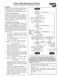
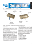
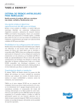
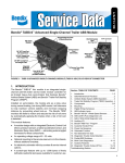
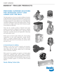
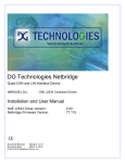
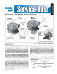
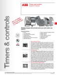
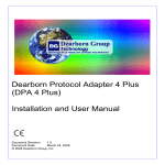
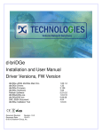
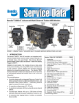
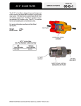
Bendix TABS-6™ Standard and Premium Trailer ABS Controller Checklist
®
• This checklist only takes a few minutes.
Follow all General Safety Guidelines (see back page.)
c R. Front
Axle WSS
Front
of
Trailer
c Additional
Modulator
Valve?
c R. Middle
Axle WSS
TABS-6
ABS
Controller
c L. Front
Axle WSS
Step 1
c R. Rear
Axle WSS
c Additional
Modulator
Valve?
c L. Rear
Axle WSS
c L. Middle
Axle WSS
What equipment does the trailer have?
Record the total of checked boxes: ______ Wheel Speed Sensors (WSSs), ______ Modulator Valves (MVs).
Step 2
What Blink Code (BC) numbers are shown as active or intermittent?
We recommend that you use a PC/laptop with associated RP1210 harnesses, etc. to connect to the trailer. The computer will need the Bendix
ACom Diagnostics software (version 6.5 and above). (For a free software download of Bendix ACom Diagnostics, visit www.bendix.com.)
Look up active and recurring/intermittent Diagnostic Trouble Codes (DTCs) and their equivalent BCs.
®
®
Record the active and recurring/intermittent BCs found using ACom Diagnostics here: ___________________________________
If a PC with ACom Diagnostics is not available, read the box below.
How to retrieve active DTCs, when ACom Diagnostics is not available:
1. Wait at least two seconds after switching the ignition ON.
2. Depress and release the stop lamp switch (or the brake pedal) three (3) times within 15 seconds after switching the ignition ON.
3. After a pause of five (5) seconds, the ECU will begin responding with active Blink Codes (BCs).
For example, seven blinks... pause... two blinks = 7-2. There is a long pause before any further BCs.
To Obtain Inactive DTCs — Switch off and re-apply the ignition power. Then depress and release the stop lamp switch (or the brake pedal) four (4) times
within 15 seconds to display the BCs of all of the inactive diagnostic trouble codes.
Record the active and recurring/intermittent BCs found here: __________________________________________________________
For each BC, use the table
Step 3 to the right and find the
recommended action code
to use. Open this document and follow
the troubleshooting checks for that code.
The actions shown will typically resolve
the issue.
See the Service Data Sheet for complete
troubleshooting information, and for any
other BCs not listed. Only go to Step 4
in cases where the troubleshooting
suggested, and any actions the technical
help line(s) recommend, do not resolve
the issue.
Bendix Technical Help
Line: 1‑800‑AIR‑BRAKE
(1‑800‑247‑2725), option 2-1,
Mon. - Fri., 8 a.m. - 6 p.m. ET.
Blink Codes (BC)
Equivalent Diagnostic
Trouble Codes (DTCs)
Description
1st code
2nd code
SID
code
2
1-4
1
0-5
SL WSS Signal
3
1-4
2
0-5
SR WSS Signal
4
1-4, 6
3
0-5, 13
SAL WSS Signal
5
1-4, 6
4
0-5, 13
SAR WSS Signal
2
5
1
13
SL Tire Configuration
3
5
2
13
SR Tire Configuration
4
5
3
13
SAL Tire Configuration
SAR Tire Configuration
FMI code
5
5
4
13
6
Any
251
3, 4, 13
7
Any
42
3, 4, 5, 6, 12 Modulator 1 DTC
8
1-3
43
3, 4, 5, 6, 12 Modulator 2 DTC
9
8
9
10
1-3
4
4
Any
44
3, 4, 5, 6, 12
8
13
9
13
1-7, 7-4, 7-7, 9-4
Modulator 3 DTC
Modulator 2 Configuration Error
Modulator 3 Configuration Error
Modulator Common
11
Any
254
12, 13
Electronic Control Unit (ECU)
12
Any
250
3, 4, 5, 12
J1587 Diagnostic
13
Any
81
3, 4, 5, 12
Trailer-Mounted ABS Indicator Lamp
Power
Open This
Document
and Take the
Action Code
Shown Below
Take Action Recommended in Step 3
Action
Code
Troubleshooting Checks To Make First
Then Do This
c Verify that the number of WSSs found in Step 1 match the stored configuration
c Verify that the sensor wiring has no visible damage or has no shorts to ground or battery
c Verify proper tire inflation
c Check that the WSS’s face is touching the exciter ring/tone ring face
c Verify 950-1950 ohms across sensor leads. Reading: .............. ohms*,
c While turning the wheel at 0.5 revs/sec, verify a minimum of 0.25 AC volts across the sensor leads.
Reading: ........ volts*
* Out of range? – go to the Bendix BW2453 WSS inspection guide
c Verify correct tire size as desired
c Verify proper tire inflation
c Verify correct number of exciter ring teeth, on both sides of the axle
c Verify that the ECU has the proper tire size settings
c Verify that the wiring and connections are free from damage
c With ignition power to the trailer, measure voltage between
the Ignition Power pin and the Ground pin of the ECU
harness connector. Repeat voltage measurement with
Brake Lamp Power pin and Ground pin of the ECU harness
connector. The operating range of the module is 8.0-16.0
VDC. Verify that voltage measurements are equal to
vehicle voltage at both ends of the harness.
Readings:
Ignition pin _____ Vdc
Brake Lamp Power pin _____ Vdc
(Incorrect? Then investigate the harnesses and connectors)
c If the proper voltage is measured at the ECU harness
connector, and no corrosion or damage is found on the
wiring connectors or ECU, then replace the module. Go
to Step 4.
c If the BC is 7-1 or 7-2, clear the active BC and cycle the
power. Check the BC again, and if the same code is
returned, replace the module. Go to Step 4.
c Check the following pins if the system is equipped with more
than one modulator (Bendix TABS-6 Premium ECU only):
• 3.0 to 8.0 Ohms across the Hold/Common connector pins
• 3.0 to 8.0 Ohms across the Exhaust/Common pins
• 6.0 to 16.0 Ohms across the Hold/Exhaust pins
• No continuity should be measured from any modulator pin
to ground
• Vbat is not measured from any modulator connector pin
• Modulator/connector wiring and pins should not be damaged
or corroded
Looking into
the system’s
main ECU wire
harness 18‑Pin
connector
(Bendix ®
TABS‑6
Premium)
Pin 6 (Ignition Power), Pin 12 (Brake Lamp
Power), Pin 18 (Ground)
Looking into
the system’s
main ECU wire
harness 5‑Pin
Connector
(TABS‑6
Standard)
Pin B (Ignition Power)
Pin A (Brake Lamp Power) Pin E (Ground)
(Looking
into the wire
harness
connector)
18‑Pin
Connector
(TABS-6
Premium)
Pin 3 is MOD2 Common, Pin 4 is MOD3
Common
Pin 9 is MOD2 exhaust, Pin 10 is MOD3
exhaust
Pin 15 is MOD2 Hold, Pin 16 is MOD3
Hold
Looking into
Modulator
Connector
Pins:
Pin 1 (Release), Pin 2 (Common)
Pin 3 (Hold)
c Verify the correct ABS configuration using blink codes or other diagnostic tool(s).
If needed, reset to the default ABS configuration and power-up to initiate an auto-configuration.
• Clear the Blink
Codes (BCs)
• Is the same BC
back?
c Yes – see the
Service Data sheet
Troubleshooting
section and/or
contact the Bendix
Tech Team
c No – follow the
actions above for
any other remaining
BCs
Take Action Recommended in Step 3
Action
Code
Troubleshooting Checks To Make First
Then Do This
c Check the modulator wiring and also look for corrosion of its connector pins
c At the modulator harness, no continuity should be measured from any modulator pin to ground.
c Vbat is not measured from any modulator connector pin
c Verify proper modulator-valve activation (during the system start-up Chuff Test) with brake pressure
applied at power-up and/or using diagnostic tool. The wiring to the modulator may be reversed
c Refer to Action A and check for proper function and configuration of the WSS
c For a code of 11-1, check for damaged or corroded connectors and wiring. Clear DTCs if no problems
are found. If a DTC returns upon ignition ON, replace the module. Go to Step 4.
c For a code of 11-2, verify correct ABS configuration using blink codes or other diagnostic tool(s).
c If needed, reset the default ABS configuration and power-up to initiate auto-configuration. See Action E.
c Check for corroded/damaged wiring or connectors between the ECU
and J1587 Diagnostic
• Clear the Blink
Codes (BCs)
• Is the same BC
back?
6
12
c Verify the following at the 18-pin ECU harness connector:
18
• +12V is not measured at the J1587 Diagnostic pins
• No continuity of the J1587 diagnostic pins to ground
• No continuity of the J1587 diagnostic pins to any other ECU pin(s)
c Verify the following at the J1587 4-pin Diagnostic connector:
• +12V is not measured at J1587 Diagnostic pins.
• No continuity of the J1587 diagnostic pins to ground
• No continuity of the J1587 diagnostic pins to any other ECU pin(s)
• Replace/repair J1587 Diagnostic wiring or components as required
Looking into Premium TABS‑6
Module Wire Harness, ECU
Connector Measure:
Pin 6 (Ignition Power),
Pin 18 (ground) and Pin 12
(Brake Light Power) to
Pin 1 (J1587+) and
Pin 7 (J1587-)
c Yes – see the
Service Data sheet
Troubleshooting
section and/or
contact the Bendix
Tech Team
c No – follow the
actions above for
any other remaining
BCs
c Check for corroded/damaged wiring or connectors between the ECU and the
ABS indicator lamp.
At the ECU harness connector [Pin D of the 5-pin, or Pin 5 of the 18-pin], verify
the following:
• Continuity of the ABS indicator lamp wiring to the lamp (auxiliary device)
• +12V is not measured at ABS indicator lamp lead
Verify the following at the ABS indicator lamp lead:
• No continuity of the ABS indicator lamp lead to ground
• No continuity from the ABS indicator lamp lead to any other ECU pin(s)
• Replace/repair the ABS indicator lamp wiring or components as required
Reference Documents - Bendix® Service Data sheets:
SD-13-4767 (Bendix® TABS-6™ Trailer ABS Module standard & premium controllers.)
Visit www.bendix.com for free downloads of Service Data Sheets, Warranty Policies, or to download/order copies of the SD sheets
Step 4
(If necessary)
Replace the ECU. If it is still under warranty coverage, file a claim and include:
a) the returned part; b) a copy of this document; and c) a print-out of the Bendix ACom Diagnostics report.
®
®
VIN #: ______________________________________________________ Claim #: ___________________
Vehicle Make: _________________________________________ Model: _______________ Mileage: _______________
To Reset the DTCs Using
a Bendix ® TRDU™
To Reset the DTCs Using Bendix ®
ACom® Diagnostics
• R eset Diagnostic Trouble Codes by
holding a magnet over the reset of the
• Use the Reset Diagnostic Codes feature.
Bendix ® Trailer Remote Diagnostic Unit
(TRDU™) tool for less than 6 seconds.
Alternate Method to Reset the DTCs
• Depress and release the stop lamp switch (or brake pedal) five (5)
times within 15 seconds of switching the ignition ON to reset the
diagnostic trouble codes. There will be a BC of 1-1 will be displayed
if all trouble codes were cleared but if any trouble codes remain the
ABS light will remain on.
Log-on and Learn from the Best
On-line training that's available when you are — 24/7/365.
Visit www.brake-school.com.
BW2910 ©2013 Bendix Commercial Vehicle Systems LLC, a member of the Knorr-Bremse Group. 7/13. All Rights Reserved.