1
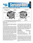
EC-15™ ANTILOCK
CONTROLLER
AR-1™ ANTILOCK RELAY
VALVE
TYPICAL
MOUNTING
BRACKET
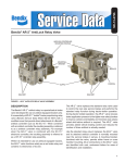
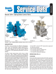
FIGURE 2 - CR-15™ ANTILOCK RELAY CONTROLLER
provides for rapid exhaust of control air pressure from
above the relay piston. The standard AR-1™ valve is offered
with a 4 psi crack pressure, however, with the addition
of various springs beneath the relay piston, higher crack
pressures are possible.
The AR-1™ valve’s internal components are interchangeable
with the R-12® and R-14® relay valves, therefore, the same
maintenance kit is used to service all three valves.
OPERATION
BRAKE APPLICATION
Brake application air enters the AR-1™ valve’s service port
and encounters the exhaust diaphragm which flexes in
response to the incoming air, sealing the exhaust passage
in the cover. Air flows around the exhaust diaphragm and
moves through a passage in the cover to the top of the
relay piston. In response to air pressure, the relay piston
2
moves into contact with the exhaust portion of the inlet and
exhaust valve. With the exhaust passage sealed, continued
movement of the relay piston unseats the inlet portion of
the inlet and exhaust valve, allowing supply air from the
reservoir to flow out the AR-1™ valve’s delivery ports to
the antilock modulators and then to the brake actuators.
(See Figure 3)
HOLDING-BALANCED
The air pressure being delivered to the antilock modulators
and brake actuators is also present beneath the relay
piston. When the air pressure above and below the relay
piston is equal, the piston moves slightly allowing the inlet
valve to return to its seat. The exhaust valve remains
closed. With both the inlet and exhaust valves closed, air
pressure in the antilock modulators and brake actuators
is held stable and neither increases nor decreases. (See
Figure 4)