1
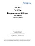
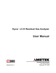
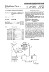
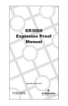
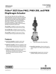
SD-06-1801
®
Bendix® TE-1™ Trailer Emergency Stop Light Switch
TERMINALS
SPRING
DIAPHRAGM
PLUNGER
FIGURE 1
TE-1™ TRAILER EMERGENCY STOP LIGHT SWITCH IN
TP-2™, TW-1™ TRACTOR PROTECTION SYSTEM.
TW-1™ TWO WAY
CONTROL VALVE
TE-1™ TRAILER EMERGENCY STOP LIGHT SWITCH IN
TP-3™, PP-3™ TRACTOR PROTECTION SYSTEM.
PP-3™ TRAILER
SUPPLY VALVE
SUPPLY
SUPPLY
SUPPLY AND
MOUNTING
PORT
OPTIONAL TE-1™
TRAILER EMERGENCY
STOP LIGHT SWITCH
SUPPLY POINTS
TP-2™ TRACTOR
PROTECTION VALVE
SUPPLY AND
MOUNTING
PORT
OPTIONAL TE-1™
TRAILER
EMERGENCY STOP
LIGHT SWITCH
SUPPLY POINTS
TP-3™ TRACTOR
PROTECTION VALVE
TRAILER
EMERGENCY
TRAILER
EMERGENCY
FIGURE 2
FIGURE 3
DESCRIPTION
If air pressure in the air brake system reduces to
approximately 60* psi for any reason, the spring overcomes
the pressure under the diaphragm, closes the contacts and
lights both tractor and trailer stop lights.
The trailer emergency stop light switch is an electropneumatic switch and lights the trailer stop lights if pressure
in the tractor emergency line reduces to approximately 60*
psi for any reason, or if the tractor protection valve is operated
manually.
Continued reduction of air pressure will disconnect tractor
stop lights but the trailer stop light will continue to light.
Referring to Figure 1 (Sectional View), with air pressure
above approximately 60* psi in the line in which the switch
is connected, air pressure acting upon the diaphragm under
the plunger overcomes pressure of the spring and keeps
the contacts separated.
*Older switches were set at 55 psi.
1
TE-1™ TRAILER EMERGENCY STOP LIGHT SWITCH WIRING DIAGRAM
ACCESSORY POLE, IGNITION
SWITCH, ETC., THAT IS OFF
WHEN ENGINE IS OFF
TRACTOR STOP
LIGHT SWITCH
TRACTOR STOP LIGHTS
IGN
TLR
BATTERY
TE-1™ TRAILER
EMERGENCY STOP
LIGHT SWITCH
ELECTRICAL
COUPLING
TTR
TRAILER STOP LIGHTS
FIGURE 4
PREVENTIVE MAINTENANCE
Important: Review the Bendix Warranty Policy before
performing any intrusive maintenance procedures. A warranty
may be voided if intrusive maintenance is performed during
the warranty period.
REMOVING
A. Place tractor protection control valve in emergency
position.
B. Disconnect electrical connections at switch.
C. Remove switch.
No two vehicles operate under identical conditions; as a
result, maintenance intervals may vary. Experience is a
valuable guide in determining the best maintenance interval
for air brake system components. At a minimum, the TE-1™
valve should be inspected every 6 months or 1500 operating
hours, whichever comes first, for proper operation and
electrical connections. Should the TE-1™ valve not meet
the elements of the operational tests noted in this document,
further investigation and service of the valve may be required.
INSTALLING
TESTING FOR SERVICEABILITY
WARNING! PLEASE READ AND FOLLOW
THESE INSTRUCTIONS TO AVOID
PERSONAL INJURY OR DEATH:
A. Operating Test
1. With ignition switch on and system fully charged,
make and hold a foot valve application and note that
stop lights on tractor and trailer are functioning
properly.
2. Place tractor protection control valve in the
emergency position and note that the trailer stop
lights are functioning properly.
3. Place tractor protection control valve in normal
position and reduce air pressure in system by making
several foot valve applications or by slowly draining
reservoirs and observing dash gauge; note that trailer
stop lights function at approximately 60* psi.
B. Leakage Test
Coat the entire switch with soap solution and check for
leaks; no leakage permitted.
If the trailer emergency stop light switch does not function
as described or if leakage is present, it is recommended
that the switch be replaced with a new switch available at
the nearest Bendix authorized distributor.
No attempt should be made to disassemble and repair faulty
switch.
*Older switches were set at 55 psi.
2
(Refer to piping diagrams - Figure 2 and Figure 3.)
A. Install in delivery port of tractor protection control valve
or in control line between control valve and tractor
protection valve. Alternate installation can be made with
a tee connection off the emergency line after the tractor
protection valve.
B. Wire as per wiring diagram (Figure 4).
When working on or around a vehicle, the following
general precautions should be observed at all times.
1. Park the vehicle on a level surface, apply the
parking brakes, and always block the wheels.
Always wear safety glasses.
2. Stop the engine and remove ignition key when
working under or around the vehicle. When
working in the engine compartment, the engine
should be shut off and the ignition key should be
removed. Where circumstances require that the
engine be in operation, EXTREME CAUTION should
be used to prevent personal injury resulting from
contact with moving, rotating, leaking, heated or
electrically charged components.
3. Do not attempt to install, remove, disassemble or
assemble a component until you have read and
thoroughly understand the recommended
procedures. Use only the proper tools and observe
all precautions pertaining to use of those tools.
4. If the work is being performed on the vehicle’s air
brake system, or any auxiliary pressurized air
systems, make certain to drain the air pressure from
all reservoirs before beginning ANY work on the
vehicle. If the vehicle is equipped with an AD-IS™
air dryer system or a dryer reservoir module, be
sure to drain the purge reservoir.
5. Following
the
vehicle
manufacturer’s
recommended procedures, deactivate the electrical
system in a manner that safely removes all
electrical power from the vehicle.
6. Never exceed manufacturer’s recommended
pressures.
7. Never connect or disconnect a hose or line
containing pressure; it may whip. Never remove a
component or plug unless you are certain all
system pressure has been depleted.
8. Use only genuine Bendix ® replacement parts,
components and kits. Replacement hardware,
tubing, hose, fittings, etc. must be of equivalent
size, type and strength as original equipment and
be designed specifically for such applications and
systems.
9. Components with stripped threads or damaged
parts should be replaced rather than repaired. Do
not attempt repairs requiring machining or welding
unless specifically stated and approved by the
vehicle and component manufacturer.
10. Prior to returning the vehicle to service, make
certain all components and systems are restored
to their proper operating condition.
3
BW1595 © 2004 Bendix Commercial Vehicle Systems LLC All rights reserved. 3/2004 Printed in U.S.A.
4