1
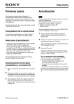
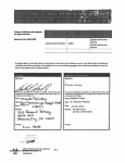
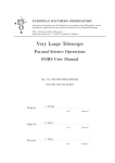
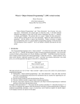
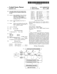
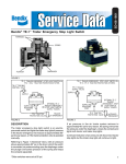
lllllllllllllllllIlllllllllllllllllllIlllllllllllllllllllllllllllllllllllll
_
US00510579OA
UI'lltEd States Patent [19]
[11] Patent Number:
Nye, Jr.
[45]
[54] CURRENT CONTROLLED FLUID BLEED
[76] Inventor!
Dudley D- Nye! Jr" 4020 631‘ Ocean
Dl'w #6O61FOYT Lauderdale, Fla33308
5,105,790
Date of Patent:
Apr. 21, 1992
OTHER PUBLICATIONS
Moore Products Co. Spring House, Pa., Model 771, UP
Transducers Installation/Service Manual, Feb. 1986.
Hammel Dahl Electropneumatic Transducer Model
'r-zs Grinnell Valve Co., Warwick, R.l., Dec. 1977,
Instructions HDC 14048.
Fisher Controls Kent ME, England Model 546 and
[21] Appl' NO‘: 633’394
546$, Electropneumatic Controls Bulletin 62.1:546,
Feb. 1981.
[22] Filed:
Dec. 21, 1990
Primary Examiner-Noah P. Kamen
Attorney, Agent, or Firm-Alvin S. Blum
[51]
1111. CLS ............................................ .. F02B 43/00
[57]
[52]
U_-S- C]- t - - ~ - - - - ' - ~ - - - -
A ?uid bleed device for controlling the amount of natu
- t - ~ -- 123/5271 251/1292
Fleld of Search ................ ..
[56]
fa] gas Supplied to the carburetor of a turbocharged
251/ 129-22
carburetednatural gas engine provides a regulated out
put ?uid pressure to the setpoint of the natural gas sup
ply regulator feeding the carburetor. This regulated
output ?uid pressure is related to the magnitude of two
input variables, the turbocharger output pressure and an
__ 137/82
137/32
electric signal from an exhaust gas sensor re?ecting the
engine exhaust gas composmon. Turbocharger air input
_
References C'ted
U.S. PATENT DOCUMENTS
3,621,862 11/1971 wojtecki _______ __
3,799,498 3/1974 wickham et al.
4,084,539
4/1978
Schmidt _ _ _ _ _ _ _ _ _ _
4,294'214 10/1981 Treible
4,325,399
4/1982
ABSTRACT
_ _ _ " 113/3
to the bleed device passes through two restrictive ori
, 137/495
?ces and a nozzle in series. The nozzle is variably oc
Frick . . . . . . .
. . . . . .. 137/85
4,481,967 11/1984 Frick ..... ..
137/85
magnet powered by the electric signal. The regulated
output ?uid pressure is taken from the junction between
416531523
3/1987
Brow" ------- -
137/85
4,665,938
5/1987
Brown et al7
i. l37/85
4,729,398
3/1988 Benson et al.
137/82
4,811.720
3/1989
4,836.0“
6/1989 Dombrowski er a].
Katumata et al. .... ..
"Liza/527
~~~~ " 73/4 R
4,1174‘oo5 10/1990 Potter .................................. .. 137/85
cluded by a movable member controlled by an electro
the two restrictive ori?ces to su
l
a
, ‘
outlet pressure and the exhaust gas composmon for
enhanced engine eff-‘Clancy
4.90l.756 2/1990 Rovner
4,905,720
3/1990 Benson ................................ .. 137/82
20\
ressure to the
p turbocharger
gas supply regulator that is relatedpptoyboth
5 Claims, 3 Drawing Sheets
US. Patent
Apr. 21, 1992
Sheet 2 of 3
5,105,790
FIG.
my
“my?
“1/2.
\wm%5
\7%
\
\ \,,_
58
.w/WQM
112..
§/ / %, w;
w/9
US. Patent
Apr. 21, 1992
Sheet 3 of 3
5,105,790
T.
607
63
\_e2
'
FIG. 4
5 P816 TURBO
INPUT TO OUT
PRESSURE DROP PSI
I
2
3
INPUT CURRENT MA
4
5
1
5,105,790
2
as input, supplies regulated gas (typically 5 psig) 14 to
carburetor 16. The engine speed is controlled by gover
CURRENT CONTROLLED FLUID BLEED
nor 18 in conjuction with butter?y valve 20 at outlet of
carburetor 16. Engine intake manifold 17 conducts air
and gas mixture to the engine. Gas pressure 14 is set by
BACKGROUND OF INVENTION
This invention relates to a stable and calibratable ?uid
bleed unit which can be used as a controlling element in
the setpoint spring 22 in regulator 12 and by the pres
air/fuel control systems for turbocharged carbureted
natural gas reciprocating engines. Presently, com
sure biasing or loading pressure from the current con
trolled bleed device 24 of the invention. The current
pressed air from the turbocharger is used as a loading
pressure on the spring or setpoint side of the gas pres
sure regulator. Gas pressure to the carburetor is then
controlled bleed unit 24 is supplied with compressed air
from the turbocharger 19 after the intercooler 23 and it
also receives dc. current via cable 29 from the propor
tional plus integral air/fuel ratio controller 28. Current
automatically increased when more air produced by the
turbocharger and this combined with the design of the
is not quite good enough, however, for obtaining maxi
controlled bleed unit 24 has a small exhaust ?ow from
outlet 25. This is air exhaust in the system 10 since the
supply air applied to the bleed unit 24 is air from turbo
mum life from a catalytic converter when used, and for
charger 19. The control loop is closed by supplying
minimizing pollution.
controller 28 with an electrical signal from oxygen
sensor 30, located in the exhaust manifold of the engine.
carburetor keeps the air/fuel ratio about constant. This
The current controlled ?uid bleed device of this in
vention is used to bleed and reduce the air pressure
FIG. 2 is a cross section view of the current con
applied to the setpoint side of the fuel gas regulator, set
trolled bleed unit 24 of the invention. The device incor
porates balance shaft 32, ?exures 34 spring bias ?exures
34'. force coil 36, coil terminals 37, magnet 38, soft iron
to run the engine slightly rich, so as to trim the air/fuel
ratio in response to the current output of a proportional
plus integral controller. This results in more perfect
control of the air/fuel ratio.
25
SUMMARY OF INVENTION
The current controlled bleed unit of the invention
resembles, in some respects, certain current to air pres
sure transducers available for industrial instrumentation
systems except that is does not have an output pressure
dependent on d.c. input current only. The output pres
sure of the bleed unit of the invention is a function of a
pressure input as well as the dc. input current. A closed
pole piece 40, nozzle 43, nozzle ori?ce 46, input ori?ce
44, channel 48, input pressure port 49, output pressure
port 50, zeroing magnets 52, zero adjustment 54, damp
ing vane 56, damping oil 58, exhaust port 59 and unit
enclosure 60. When an electric current passes through
force coil electromagnet 36, the magnetic ?eld gener
ated therein opposes the ?eld of magnet 38, forcing the
balance shaft 32 upward.
With the device depicted as in FIG. 2, an input cur
rent into force coil 36 causes balance shaft 32 to ap
proach the open end of nozzle 43, and at this point, with
loop air/fuel ratio control system is reduced in com
the proper setting of zero adjustment 54, nozzle 43 is not
35
plexity by using the bleed unit of the invention. This
materially obstructed with respect to air ?ow, resulting
results in lower costs and increased reliability.
in maximum air ?ow through ori?ces 44 and 46. The
It is therefore one object of the invention to provide
pressure drop at outlet port 50 is then near its maximum
a ?uid bleed unit controlled by a dc. current (usually
with these settings. As balance shaft 32 moves closer to
1-5 mA or 4-20 mA.).
Another object is to provide a ?uid bleed unit which 40 nozzle 43 air flow is reduced, reducing the pressure
can be used on natural gas as well as air.
Another object of the invention is to set forth a com
drop at outlet port 50 until nozzle 43 is completely
sealed off. When nozzle 43 is completely sealed off
there is no pressure drop at outlet port 50 and the pres- ,
plete closed loop control system for air/fuel ratio con
sure is equal to input pressure at port 49. The pressure in
trol incorporating the current controlled bleed unit of
45 nozzle 43 is self adjusting, up to the point of being sealed
the invention.
off, such that the ?uid force on balance shaft 32 bal
These and further objects and advantages of the in
ances the force produced by force coil 36 and other
vention will become more apparent upon reference to
forces on balance shaft 32. This insures that device 24 of
the following speci?cations, drawings and claims
the invention has stable and linear characteristics. Zero
wherein.
ing magnets 52 oppose each other to support balance
BRIEF DESCRIPTION OF THE DRAWINGS
shaft 32 and to provide for a calibration adjustment via
screw 54. Damping vane 56in damping oil 58 prevents
FIG. 1 is a simpli?ed drawing of a fuel to air ratio
the closed loop mechanical spring and mass system
control system incorporating the current controlled
from oscillating. Alternatively, the buoyancy of damp
bleed unit of the invention.
FIG. 2 is a cross sectional drawing showing the con 55 ing vane 56 and the spring bias of ?exures 34' may be
arranged to provide sufficient upward bias to balance
struction of the current controlled bleed unit of the
shaft 32 to eliminate zeroing magnets 52.
invention.
FIG. 3 is block/schematic drawing of the current
FIG. 3 is a combination block diagram and equivalent
controlled bleed device of the invention. Here signal 49,
schematic for the bleed unit of the invention.
FIG. 4 is a graph representing the input to output 60 representing pressure from the turbocharger in FIG. 1,
is directed to the input of ori?ce 44 and the output of
pressure drop of a typical bleed unit as a function of
ori?ce 44 is connected to a terminal representing the
input dc. current and input pressure.
outlet pressure port 50 of device 24 of FIG. 1. Flow,
DETAILED DESCRIPTION OF THE
controlled by the pressure at 63 determines the drop in
PREFERRED EMBODIMENTS
65 outlet pressure 50. Current input 60 controls pressure 63
via block 62. The transfer function for the ratio of a
FIG. 1 shows an air/fuel ratio control system 10 for
pressure change at 50 to a current change at 60 is essen
use with turbocharged carbureted natural gas engine. In
tially constant for a given selection of ori?ces 44 and 46.
this system gas pressure regulator 12, with gas supply 15
3
5,105,790
4
This is important when considering the proportional
a stationary second magnetic means connected to said
gain of the closed loop system of FIG. 1. It has been
suggested by others that the variable bleed device might
body member and arranged to interact magneti
cally with said ?rst magnetic means to thereby
apply a moving force to said movable member for
variably occluding said outlet end of said nozzle, at
incorporate a motor positioned needle valve for ori?ce
46. But this would result in variation ofthe proportional
loop gain of the closed loop system of FIG. 1 and result
in sluggish response at the low ?ow end of ori?ce 46
settings. A modi?ed gas pressure regulator 90 reduces
and controls the pressure of fuel gas coming from a
supply 15 by opening and closing valve 92 that is con 10
least one of said magnetic means being an electro
magnet in which a magnetic ?eld is generated by
an electric current applied thereto by said variable
electric current;
whereby said electric current controls the magnetic
nected to diaphragm 91 until the forces on both sides of
force regulating the force on said movable member
diaphragm 91 are equal. Gas pressure in chamber 94 is
the only force on a ?rst side of the diaphragm and will
re?ect the regulator outlet pressure in conduit 14 sup
plying fuel to the carburetor 16. The second side of
diaphragm 91 has two forces acting on it: An adjustable
spring bias 22 which is well known in the art, and a
second force, the gas pressure in chamber 26, as sup
plied by conduit 93. This controlling gas pressure is
regulated by a sensor 30 in the exhaust stream of the 20
engine (not shown) to modulate the carburetor fuel
for variably occluding said nozzle, and the force
occluding said nozzle regulates the ?ow of said
pressurized supply ?uid through said restrictions
and past the partially occluded nozzle, and the ?uid
pressure at said outlet port will be substantially
equal to the pressure at the outlet of said second
restriction and that pressure will be controlled by
the magnitude of said electric current in combina
tion with the pressure of said pressurized supply
?uid.
2. A current controlled bleed device according to
supply for cleaner fuel burning to reduce stress on the
environment and any catalytic converter.
claim 1 in which said bias force is provided by a spring
connected between said movable member and said body
current controlled bleed device of the invention as a 25 member.
3. A current controlled bleed device according to
function of input pressure derived from the turbo
claim 1 in which said bias force is obtained by magnetic
charger and the input current derived from the air/fuel.
The turbocharger pressure is initially at a very low
force provided by permanent magnets with one magnet
connected to said body member and another magnet
value when the engine is ?rst started. It then gradually
connected to said movable member.
builds up with engine temperature and load application.
4. The bleed device according to claim 1 further
The turbocharger air output pressure reaches a maxi
comprising:
mum value, oftypically 5 psig. as controlled by a regu
a fuel gas pressure regulator having an inlet for a
lator (not shown) on the engine exhaust side of the
supply of fuel gas and an outlet for supplying gas
turbocharger. Since the lines in the graph shown are
FIG. 4 shows the input to output pressure drop of the
almost parallel there is very little proportional gain
change, when considering the closed loop system of
35
fuel to an internal combustion engine at a con
trolled gas pressure regulated by the composition
FIG. 1.
The invention has been described with reference to
of exhaust gas emitted by said engine, in which said
the preferred embodiments. Obviously, modi?cations
sure regulator provided with a diaphragm having
and alterations will occur to others upon reading and
understanding the preceding detailed descriptions. It is
two broad faces with said gas fuel on a ?rst broad
face and a controlling force applied to a second
intended that this invention be construed as including
all such alterations and modi?cations insofar as they
come within the scope of the appended claims or the
broad face, said controlling force provided by a
setpoint spring and by a loading or biasing ?uid
pressure in combination;
equivalents thereof.
Having thus described the preferred embodiments,
controlled gas pressure is controlled by a gas pres
45
a conduit connection means for ?uid connection be
tween said pressure regulator and said outlet port
of said bleed device for providing said biasing ?uid
the invention is now claimed to be:
1. An electric current controlled ?uid bleed device
pressure; and
comprising:
an exhaust gas sensing means for sensing the composi
ton of the exhaust gas from the engine, said sensing
a body member having a ?uid inlet port, an outlet 50
means including means for generating said variable
port, and an exhaust port, said inlet port arranged
electric current for applying to said electromagnet
for supplying pressured ?uid thereto;
of said bleed device.
a movable member with a ?rst magnetic means for
5. A transducer for providing an output ?uid pressure
providing a magnetic ?eld rigidly attached thereto;
a channel connecting said inlet port to said outlet 55 whose magnitude is related to the magnitude of two
port; a branch line connected intermediate said
different input variables, an inlet ?uid pressure and an
channel to be variably occluded by said movable
inlet electrical current, the transducer comprising:
a) a transducer body having a pressurized ?uid inlet,
member; two restrictions, a ?rst restriction located
in said branch line and a second restriction located
in said channel upstream of said branch line,
a ?uid pressure outlet, a ?uid exhaust port, and an
60
a nozzle having an inlet end and an outlet end, with
the outlet end arranged to be variably occluded by
electrical current input;
b) a channel connecting said ?uid inlet to said ?uid
pressure outlet; a branch line connected intermedi
said movable member and with the inlet to said
ate said channel; two restrictions, a ?rst restriction
nozzle communicating with said branch line
located in said channel upstream of said branch line
conduit means for conducting ?uid from said nozzle 65
to said exhaust port;
bias means for applying a bias force between said
movable member and said body member; and
and a second restriction located in said branch line;
an aperture means for conduction of ?uid there
through located in said branch line downstream of
said second restriction, said ?uid exhaust port
5
5,105,790
being connected downstream of said apperture
6
occludes said aperture means with a force that
varies in relation to said electrical current;
means in said branch line; and
c) a movable member having attached thereto an
whereby the outlet ?uid pressure re?ects the inlet ?uid
pressure minus the pressure drop across the ?rst restric
tion, and the pressure drop across the ?rst restriction is
related to the ?uid ?ow therethrough which is related
aperture-occluding means for variably occluding
said aperture means, said movable member ar
ranged t'or movement within said body under a
moving force generated by a biasing means in com
bination with a variable electrical current supplied
by connection to said electrical current input,
wherein said aperture-occluding means variably
to the occluding force produced by said variable electri
cal current.
'
15
25
35
45
55
65
t
I
t
i