1
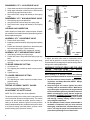
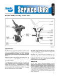
DISASSEMBLY: ST-1™ ADJUSTABLE VALVE
1. Clamp lower wrench flat in vise (flat nearest pipe thread).
2. Using upper wrench flat, unscrew lock nut. Unscrew and
remove spring cage from body of valve.
3. Remove ball valve, spring and release pin from spring
cage.
RELEASE
PIN
ADJUSTING
NUT
LOCK
NUT
SPRING
CAGE
SPRING
DISASSEMBLY: ST-3™ NON-ADJUSTABLE VALVE
1. Clamp spring cage in soft jawed vise.
2. Using wrench flat, unscrew body from spring cage.
3. Remove ball valve, spring and release pin from spring
cage.
CLEANING AND INSPECTION
BALL
VALVE
BODY
PIPE
THREAD
RELEASE
PIN
Clean all parts in mineral spirits. Inspect all parts. All parts
not considered serviceable should be replaced with genuine
Bendix replacement parts.
ASSEMBLY: ST-1™ ADJUSTABLE VALVE
1. Place the ball valve in body.
2. Install spring and release pin in spring cage with adjusting
screw.
3. Position the release pin overball valve. Screw body with
ball into the spring cage. Tighten securely.
4. Adjust for proper setting (see “Adjustment” section).
ASSEMBLY: ST-3™ NON-ADJUSTABLE VALVE
1. Install spring, release pin in spring cage.
2. Position ball valve in body and screw spring cage onto
body.
3. Hold spring cage in soft jawed vise and tighten body
securely.
TO RAISE PRESSURE SETTING
ST-1™ SAFETY
VALVE
SPRING
CAGE
SPRING
BALL
VALVE
BODY
PIPE
THREAD
ST-3™ SAFETY
VALVE
To adjust, the safety valve must be connected to an air
system with air pressure in excess of desired setting. It is
important that an accurate gauge be used to check pressure
settings while making adjustments.
1. Loosen lock nut.
2. Turn adjusting nut clockwise to obtain correct pressure
setting.
3. Tighten lock nut.
WARNING! PLEASE READ AND FOLLOW
THESE
INSTRUCTIONS
TO AVOID
PERSONAL INJURY OR DEATH:
TO LOWER PRESSURE SETTING
When working on or around a vehicle, the following
general precautions should be observed at all times.
1. Loosen lock nut.
2. Turn adjusting nut counter clockwise to obtain correct
pressure setting.
3. Tighten lock nut.
TESTING OF REBUILT SAFETY VALVES:
Perform operating and leakage checks.
ADJUSTMENT OF SAFETY VALVE
NOTE: The ST-3™ safety valve is not adjustable.
The pressure setting of the safety valve is stamped on the
cover wrench flat (closest to the pipe thread). The vehicle
manual may also provide the proper pressure setting. If
setting is not known, determine governor cutout pressure
setting and adjust safety valve so that the safety valve closes
at a pressure setting somewhat above governor cutout
pressure setting (See “Operation” section).
2
1. Park the vehicle on a level surface, apply the parking brakes, and always block the wheels. Always
wear safety glasses.
2. Stop the engine and remove ignition key when
working under or around the vehicle. When working in the engine compartment, the engine should
be shut off and the ignition key should be removed.
Where circumstances require that the engine be
in operation, EXTREME CAUTION should be used
to prevent personal injury resulting from contact
with moving, rotating, leaking, heated or electrically charged components.
3. Do not attempt to install, remove, disassemble or
assemble a component until you have read and
thoroughly understand the recommended procedures. Use only the proper tools and observe all
precautions pertaining to use of those tools.