1
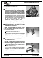
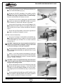
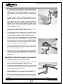
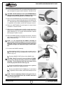
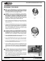
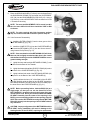
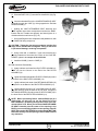
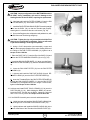
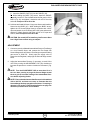
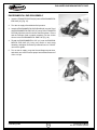
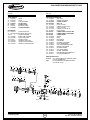
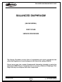
BALANCED DIAPHRAGM FIRST STAGE
R
O
BALANCED DIAPHRAGM
(INLINE SWIVEL)
FIRST STAGE
SERVICE PROCEDURE
This Service Procedure conveys lists of components and service procedures that
reflect the Regulator as it was configured at the time of the writing (3/24/03).
Future issues may also contain Supplemental Information intended to assist the
Authorized AERIS Service Technician who is servicing a Balanced Diaphragm First
Stage that may be configured with older components.
© 2002 Design 2003
1
Product Service Manual
Doc. No. 12-7509-r01 (3/24/03)
BALANCED DIAPHRAGM FIRST STAGE
R
O
CONTENTS
TROUBLESHOOTING .................................................................................................................................................................. 3
DISASSEMBLY PROCEDURE .................................................................................................................................................... 4
REASSEMBLY PROCEDURE ..................................................................................................................................................... 8
ADJUSTMENT ........................................................................................................................................................................... 12
ENVIRONMENTAL KIT REASSEMBLY .................................................................................................................................... 12
PARTS LIST AND EXPLODED VIEW DIAGRAM ...................................................................................................................... 14
REGULATOR GENERAL PROCEDURES
REFER TO ............................................................................................................................................................... DOC. 12-7508
SPECIFICATIONS
Torques
P/N 30.96767
Yoke Retainer
P/N 30.94544.200
DIN Filter Retainer
P/N 30.96766
DIN Filter Housing
P/N 30.93462
HP Port Plug
P/N 30.93463
LP Port Plug
P/N 30.96769
Swivel Post
P/N 30.6580
Environ. End Cap
HP Hose into First Stage Body
LP Hose into First Stage Body
Inflator Hose into First Stage Body
23 to 25 ft-lbs
16 to 18 ft-lbs
16 to 18 ft-lbs
35 to 40 in-lbs
35 to 40 in-lbs
40 to 50 in-lbs
33 to 34 ft-lbs
35 to 40 in-lbs
35 to 40 in-lbs
35 to 40 in-lbs
Intermediate Pressure
Recommended 138 to 142 psi
Acceptable
137 to 143 psi
TOOLS REQUIRED
Standard Tools
Inch Pounds Torque Wrench
Foot Pounds Torque Wrench
5/32" Hex Key Socket
1/4" Hex Key Socket
1/2" Open End Wrench
9/16" Open End Wrench
5/8" Open End Wrench
13/16" Open End Wrench
1" Open End Wrench
5/32" Hex Key
1/4" Hex Key (for DIN model)
5/16" Hex Key
3/8" Drive Socket
Soft Jawed Vise
© 2002 Design 2003
Specialty Tools
P/N 30.02302
P/N 30.06671
P/N 30.09311
P/N 30.09315
P/N 30.09520
2
Christo-Lube MCG111 - 2 oz
End Cap Tool Kit
Filter Circlip Pliers
Intermediate Press. Gauge
O-ring Tool Kit
Product Service Manual
Doc. No. 12-7509-r01 (3/24/03)
BALANCED DIAPHRAGM FIRST STAGE
R
O
TROUBLE SHOOTING
SYMPTOM
POSSIBLE CAUSE
TREATMENT
* Restricted airflow and
inhalation resistance through
complete system.
1. Cylinder valve not completely
opened.
2. Cylinder valve requires service.
3. CONE FILTER (4,12) is contaminated.
1. Open valve completely.
2. Connect Regulator to a
different Cylinder.
3. Replace with new and
perform a complete service.
* Air leakage detected from
beneath the ADJUSTMENT
CUP (38), inside the END
CAP (35).
1. END CAP (35) is loose.
2. DIAPHRAGM (32) is worn or
damaged.
3. Seating surface inside BODY (30)
is damaged.
1. Tighten END CAP (35) onto
BODY (30), using prescribed
torque value in Reassembly
Procedure.
2. Replace with new.
3. Replace BODY (30) with new.
* Air leakage detected from
beneath the YOKE, or DIN,
Connector.
1. YOKE RETAINER (6), or DIN
FILTER HOUSING (14), is loose.
2. RETAINER O-RING (7, 10) is
worn or damaged.
1. Tighten onto BODY (30)
using prescribed torque
value in Reassembly
Procedure.
2. Replace with new.
* Insufficient intermediate
pressure.
1. END CAP (35) is loose.
2. First stage improperly adjusted.
3. DIAPHRAGM SPRING (36) is
weakened or damaged.
4. Seating surface of BODY (30)
beneath DIAPHRAGM (32) is
damaged.
* Excessive intermediate pressure/Intermediate pressure
creeps.
1. First Stage improperly adjusted.
2. HP SEAT (20) is damaged or
worn.
3. HP SEAT O-RING (19) is damaged or worn.
4. Seating surface of HP SEAT (20)
or BODY (30) or its Orifice Cone
is damaged.
5. RETAINING SPRING (18) is
weakened or damaged.
© 2002 Design 2003
3
1. Tighten END CAP (35) onto
BODY (30), using prescribed
torque value in Reassembly
Procedure.
2. Readjust according to the
procedure specified in Final
Adjustment Procedure.
3. Replace with new.
4. Replace BODY (30) with new.
1. Readjust according to
Adjustment Procedure.
2. Replace with new.
3. Replace with new.
4. Replace with new.
5. Replace with new.
Product Service Manual
Doc. No. 12-7509-r01 (3/24/03)
BALANCED DIAPHRAGM FIRST STAGE
R
O
DISASSEMBLY PROCEDURE
NOTE: Be sure to check and record the Intermediate Pressure and perform the Leak Detection Test outlined in the
Initial Inspection Procedures (Doc. 12-7508) prior to Disassembling the Regulator. Review the Troubleshooting Section on page 3 to gain a better idea of which internal parts may
be worn, and to better advise your customer of the service
that is needed.
1. Before disassembling the First Stage, remove the Low Pressure
Hoses with a 9/16" open end wrench, the High Pressure Hose(s)
with a 5/8" open end wrench, and the Low Pressure Inflator Hose
with either a 9/16" or 1/2" open end wrench. Remove all
remaining PORT PLUGS (21, 23) with a 5/32" hex key.
Fig. 1
2. Remove and inspect the O-RING(S) now visible on all these
items for any signs of decay. If found, discard the O-RING(S).
CAUTION: It is important to remove the YOKE/DIN Connector end components first to avoid damage of the HP Seat
Cone located inside the BODY (30).
NOTE: For units received with Yoke Connectors perform
step 3Y. For those with DIN Connectors perform step 3D.
3Y. Yoke Connector Disassembly:
A. Remove the KNOB (1) from the YOKE (2)
B. Secure the BODY (30) in a soft jawed or well padded vise and
apply a thin wall, or modified, 1" open end wrench to the YOKE
RETAINER (6). Using firm steady force, turn the YOKE RETAINER counter clockwise to loosen it. DO NOT use impact.
Fig. 2
CAUTION: It is important that the wrench is properly seated
over the entire hex portion of the YOKE RETAINER to prevent
any damage to the part (Fig. 1).
CAUTION: Tighten the vise only as needed to hold the First
Stage secure, and DO NOT overtighten. Doing so will result
in permanent damage, rendering it inoperable.
C. Remove the Regulator from the vise and stand it on the work
bench with the Yoke end up (Fig. 2).
D. Lift the YOKE (2), YOKE RETAINER (6) with RETAINING
SPRING (18), and HP SEAT (20) straight up and out of the BODY
(30) (Fig. 3) and set them aside.
E. Remove the DUST CAP (17), and set it aside.
Fig. 3
© 2002 Design 2003
4
Product Service Manual
Doc. No. 12-7509-r01 (3/24/03)
BALANCED DIAPHRAGM FIRST STAGE
R
O
F. Remove the HP SEAT (20) and RETAINING SPRING (18)
from the YOKE RETAINER (6) (Fig. 4).
G. Discard the HP SEAT, regardless of its condition, and DO
NOT attempt to reuse it. Using a magnifier, closely examine the
SPRING for any signs of corrosion, cracks, or other damage.
Discard if found and DO NOT attempt to reuse it.
H. Using care not to scratch or damage the YOKE RETAINER
(6), remove and discard the RETAINER O-RING (7) and HP
SEAT O-RING (21), and DO NOT attempt to reuse them.
I. Using Internal Circlip Pliers, remove the RETAINING CLIP
(3) that retains the CONE FILTER (4). The CONE FILTER should
drop out freely into your hand. Discard, and DO NOT attempt to
reuse it.
Fig. 4
J. Remove the FILTER O-RING (5) and discard, regardless of
its condition, and DO NOT attempt to reuse it.
3D. DIN Connector Disassembly:
A. Secure the First Stage in a soft-jawed or well padded vise,
with the DIN Connector facing up. Apply a 1/4" hex key to the DIN
FILTER RETAINER (9) and loosen it in a counter clockwise
direction (Fig. 5).
Fig. 5
CAUTION: Tighten the vise only as needed to hold the First
Stage secure, and DO NOT overtighten. Doing so will result
in permanent damage, rendering it inoperable.
B. Remove the DIN FILTER RETAINER (9), COUPLER WHEEL
(11), FILTER HOUSING SPACER (16), and DUST CAP (17), and
set them aside.
C. Apply a 13/16" deep socket (recommended), or open end
wrench, to the flange at the Base of the DIN FILTER HOUSING
(Fig. 6). Using firm, steady force, loosen it in a counter clockwise
direction. DO NOT use impact.
Fig. 6
CAUTION: If used, it is important that the open end wrench
is deep enough to seat entirely over the Flange to avoid any
damage to the Seating Surface.
D. Remove the Regulator from the vise and stand it on the work
bench with the DIN Connector facing up. Lift the DIN FILTER
HOUSING (14) with RETAINING SPRING (18) and HP SEAT
(20) straight up and out of the BODY (30) (Fig. 7) and set them
aside.
E. Remove the DIN FACE O-RING (8) and RETAINER O-RING
(10) from the DIN FILTER RETAINER. Discard both, regardless
of their condition, and DO NOT attempt to reuse them.
Fig. 7
© 2002 Design 2003
5
Product Service Manual
Doc. No. 12-7509-r01 (3/24/03)
BALANCED DIAPHRAGM FIRST STAGE
R
O
F. Turn the DIN FILTER HOUSING (14) over and tap it lightly to
drop out the DIN CONE FILTER (12). Remove the FILTER ORING (13) and FILTER HOUSING O-RING (15). Discard them
both regardless of their condition and DO NOT attempt to reuse
them.
G. Remove the HP SEAT (20), RETAINING SPRING (18), and
HP SEAT O-RING (19) from the FILTER HOUSING (14) (Fig. 8).
H. Discard the HP SEAT and HP SEAT O-RING, regardless of
their condition, and DO NOT attempt to reuse them. Using a
magnifier, closely examine the RETAINING SPRING for any
signs of corrosion, cracks, or other damage. Discard if found and
DO NOT attempt to reuse it.
Fig. 8
I. Inspect the FILTER HOUSING SPACER (16), checking for
any signs of damage or distortion. Discard if found.
4. Turn the Regulator over and stand it on the work bench with the
ENVIRONMENTAL CAP (41) facing up and remove the CAP by
turning it counter clockwise by hand. DO NOT use tools.
5. Gently peel the Lip of the ENVIRONMENTAL DIAPHRAGM (40)
away from the Rim of the ENVIRONMENTAL END CAP (35) and
lift it out to remove. Examine the condition of the ENVIRONMENTAL DIAPHRAGM, checking for any signs of wear, distortion,
corrosion, or perforation. Discard if found.
6. Turn the First Stage Diaphragm side down and remove the
TRANSFER PISTON (39). Check for any signs of wear, distortion, or corrosion. Discard if found.
7. Secure the First Stage in a soft-jawed or well padded vise and
apply a Spanner Tool to the ENVIRONMENTAL END CAP (35),
turning it counter clockwise to loosen it (Fig. 9). DO NOT remove
it at this time.
Fig. 9
CAUTION: Tighten the vise only as needed to hold the First
Stage secure, and DO NOT overtighten. Doing so will result
in permanent damage, rendering it inoperable.
8. Remove the Regulator from the vise and stand it on the work
bench with the ENVIRONMENTAL END CAP (35) up.
9. While holding the ENVIRONMENTAL END CAP (35) secure with
one hand, turn ADJUSTMENT CUP (38) counter clockwise using
a 5/16" hex key to remove it (Fig. 10).
10. Hold the BODY secure with one hand and remove the ENVIRONMENTAL END CAP (35) by turning it counter clockwise.
11. Remove the DIAPHRAGM SPRING (36) and SPRING WASHER
(37). Inspect both for any signs of wear or distortion. Discard if
found.
© 2002 Design 2003
6
Fig. 10
Product Service Manual
Doc. No. 12-7509-r01 (3/24/03)
BALANCED DIAPHRAGM FIRST STAGE
R
O
12. Lift out the DIAPHRAGM PLATE (34) and DIAPHRAGM WASHER
(33), and inspect for signs of wear or distortion. Discard if found.
CAUTION: DO NOT attempt to remove the DIAPHRAGM (32)
with the use of a metallic instrument. Doing so will seriously
damage the brass Seating Surface of the BODY (30).
13. Remove the DIAPHRAGM (32) from the BODY (30) by pressing
down on it with your finger causing the edge to turn upward (Fig.
11). Grasp the edge of the DIAPHRAGM and lift it out. Discard
it, regardless of its condition, and DO NOT attempt to reuse it.
14. Remove the BUTTON/PIN (31) and inspect it for signs of wear
or distortion. Discard if found.
Fig. 11
15. With the use of a penlight and a magnifier, closely examine the
Seating Surface of the Orifice Cone inside the BODY (30) for any
signs of damage (Fig. 12). If found, discard the BODY and DO
NOT attempt to repair or reuse it.
16. Remove all PORT PLUGS (21,23) with a 5/32" hex key. Remove
and inspect the PORT PLUG O-RINGS (22,24) for any signs of
decay. Discard if found.
NOTE: It is not required that the SWIVEL Assembly be
removed each time the First Stage is serviced or to clean the
BODY (30). However, it will have to be removed to replace the
O-RINGS if leakage was detected during the Initial Inspection.
Fig. 12
17. To remove the SWIVEL Assembly:
A. While holding the BODY (30) secure with one hand, turn the
SWIVEL POST (25) counter clockwise with a 5/32" hex key to
remove it (Fig. 13).
B. Press the SWIVEL POST (25) out of the SWIVEL (29).
CAUTION: DO NOT use tools to remove the Swivel O-RINGS.
Doing so may damage the sealing surfaces of the SWIVEL
Assembly. Pinch (squeeze) them with your fingers of one
hand and grasp them with the other (Fig. 14).
Fig. 13
C. Remove the SWIVEL O-RING (28) and discard it, regardless
of condition, and DO NOT attempt to reuse it.
D. Remove the SWIVEL POST O-RINGS (26, 27) and discard
them, regardless of their condition, and DO NOT attempt to reuse
them.
NOTE: There is a small drop of Patch Lock (green color) on
the Threads of the SWIVEL POST (25). DO NOT remove this
when cleaning the POST.
Fig. 14
© 2002 Design 2003
7
Product Service Manual
Doc. No. 12-7509-r01 (3/24/03)
BALANCED DIAPHRAGM FIRST STAGE
R
O
REASSEMBLY PROCEDURE
NOTE: Prior to Reassembly, it is necessary to Inspect all
parts, both new and those that are being reused. Check to
ensure that O-rings are clean and supple, and that every part
and component has been thoroughly cleaned.
WARNING: Use only genuine AERIS parts, subassemblies,
and components whenever assembling AERIS products. DO
NOT attempt to substitute an AERIS part with another
manufacturer’s, regardless of any similarity in shape, size, or
appearance. Doing so may render the product unsafe, and
could result in serious injury or death of the user.
Fig. 15
1. Place the Stem of the BUTTON/PIN (31) directly into the Center
Hole in the BODY (30), ensuring that it enters without any
restriction (Fig. 15).
2. Position the DIAPHRAGM (32) flat, directly over the opening of
the BODY (28). Gently push the Edges of the DIAPHRAGM
down inside the Internal Threads of the BODY, one Thread at a
time. Rotate the BODY while doing this, to facilitate an even
seating of the DIAPHRAGM. Closely inspect to ensure it is well
seated at the Base of the Threads (Fig. 16).
CAUTION: DO NOT force the DIAPHRAGM into the BODY in
a manner that will damage either the Lip or Surface of the
DIAPHRAGM, or the Threads of the BODY. The use of a sharp
instrument, such as a screwdriver, is to be strictly avoided.
3. Place the DIAPHRAGM WASHER (33) into the BODY (30) on top
of the DIAPHRAGM (32) with the Collar facing up.
Fig. 16
4. Lay the DIAPHRAGM PLATE (34) into the Center of the DIAPHRAGM (32), with its Flat Surface against the DIAPHRAGM.
5. Thread the ENVIRONMENTAL END CAP (35) into the BODY
(30), turning clockwise by hand until secure.
6. Secure the BODY (30) in a soft jawed or well padded vise, and
using the End Cap Hook/Wrench Link (from End Cap Tool) and
a foot-pounds torque wrench, tighten the ENVIRONMENTAL
END CAP (35), into the BODY to a torque of 33 to 34 ft-lbs (Fig.
17).
CAUTION: Tighten the vise only as needed to hold the First
Stage secure, and DO NOT overtighten. Doing so will result
in permanent damage, rendering it inoperable.
7. Remove the Regulator from the vise and place it on the work
bench. Apply a very light film of lubricant (Christo Lube MCG
#111) to both Ends of the DIAPHRAGM SPRING (36), and place
it down onto the DIAPHRAGM PLATE (34).
Fig. 17
© 2002 Design 2003
8
Product Service Manual
Doc. No. 12-7509-r01 (3/24/03)
BALANCED DIAPHRAGM FIRST STAGE
R
O
8. Place the SPRING WASHER (37) directly onto the Upper End of
the DIAPHRAGM SPRING (36) and install the ADJUSTMENT
CUP (38) into the ENVIRONMENTAL END CAP (35). Using a
5/16" hex key, turn the ADJUSTMENT CUP clockwise until 3 OR
4 Threads are showing.
NOTE: The more the ADJUSTMENT CUP is turned in at this
time, the more difficult it will be to install the YOKE or DIN
Connector.
NOTE: For units received with Yoke Connectors perform
step 9Y, for those with DIN Connectors perform step 9D.
Fig. 18
9Y. Yoke Connector Reassembly:
A. Install the FILTER O-RING (5) into the inner groove of the
YOKE RETAINER (6) (Fig. 18).
B. Install the CONE FILTER (4) into the YOKE RETAINER (6)
and install the RETAINING CLIP (3) into the Groove above it,
using Internal Circlip Pliers (Fig. 19).
NOTE: Close examination of the RETAINING CLIP will show
that one side is slightly rounded and the other is flat. Install
with the flat side facing out of the YOKE RETAINER to ensure
greater holding strength.
Fig. 19
C. Lightly lubricate and install the RETAINER O-RING (7) onto
the Groove at the Base of the Threads.
D. Lightly lubricate and install the HP SEAT O-RING (19) into the
Inner Bore of the YOKE RETAINER (6) (Fig. 20).
E. Lightly lubricate both ends of the RETAINING SPRING (18)
and place it on the Barrel of the YOKE RETAINER (6).
F. Lightly lubricate the lower 1/4" of the Shaft of the HP SEAT
(20) and carefully guide the Shaft of the HP SEAT through the
RETAINING SPRING (18) and into the HP SEAT O-RING (19) in
the Inner Bore of the YOKE RETAINER (6) (Fig. 21).
Fig. 20
NOTE: Before proceeding further, hold the BODY (30) at a
slight angle, so that you can see the Stem End of the
BUTTON/PIN (31) protruding through the Center of the machined Orifice Cone. When you insert the YOKE RETAINER/
HP SEAT Assembly into the center of the opening in the
BODY, you must carefully guide the center opening of the HP
SEAT (20) onto the BUTTON/PIN ensuring that the BUTTON/
PIN enters directly into the opening of the HP SEAT without
any restriction.
CAUTION: Improper alignment of the BUTTON/PIN and the
HP SEAT during installation will result in damage to the
Seating Surface of the HP SEAT, requiring its replacement.
© 2002 Design 2003
9
Fig. 21
Product Service Manual
Doc. No. 12-7509-r01 (3/24/03)
BALANCED DIAPHRAGM FIRST STAGE
R
O
G. Place the DUST CAP (17) onto the Rim of the BODY (30) (Fig.
22).
H. Insert the threaded End of the YOKE RETAINER/HP SEAT
Assembly through the YOKE (2), facing opposite the End that
holds the KNOB (1).
I. Holding the YOKE RETAINER/HP SEAT Assembly and
YOKE together insert them straight down into/onto the BODY.
Ensure that the Threads seat properly and hand tighten in a
clockwise direction until secure (Fig. 23).
J. Secure the Regulator in a soft jawed or well padded vise, with
the YOKE End facing straight up.
Fig. 22
CAUTION: Tighten the vise only as needed to hold the first
stage secure, and DO NOT overtighten. Doing so will result
in permanent damage, rendering it inoperable.
K. Using a thin-wall, or modified, 1" open end wrench that is
properly seated over the entire Hex Portion of the YOKE RETAINER, tighten it to a torque of 23 to 25 ft-lbs.
L. Install the KNOB (1) into the YOKE (2).
9D. DIN Connector Reassembly:
A. Lightly lubricate and install the DIN FILTER HOUSING ORING (15) into the Groove on the End of the DIN FILTER
HOUSING (14).
B. Lightly lubricate and install the HP SEAT O-RING (19) into the
Inner Bore of the DIN FILTER HOUSING (14).
C. Lightly lubricate both ends of the RETAINING SPRING (18)
and place it on the Barrel of the DIN FILTER HOUSING (14).
Fig. 23
D. Lightly lubricate the lower 1/4" of the Shaft of the HP SEAT
(20) and carefully guide the Shaft of the HP SEAT through the
RETAINING SPRING (18) and into the HP SEAT O-RING (19) in
the Inner Bore of the DIN FILTER HOUSING (14).
NOTE: Before proceeding further, hold the BODY (30) at a
slight angle, so that you can see the Stem End of the
BUTTON/PIN (31) protruding through the Center of the machined Orifice Cone. When you insert the YOKE RETAINER/
HP SEAT Assembly into the center of the opening in the
BODY, you must carefully guide the center opening of the HP
SEAT (20) onto the BUTTON/PIN ensuring that the BUTTON/
PIN enters directly into the opening of the HP SEAT without
any restriction.
© 2002 Design 2003
10
Product Service Manual
Doc. No. 12-7509-r01 (3/24/03)
BALANCED DIAPHRAGM FIRST STAGE
R
O
CAUTION: Improper alignment of the BUTTON/PIN and the
HP SEAT during installation will result in damage to the
Seating Surface of the HP SEAT, requiring its replacement.
E. Lubricate and install the FILTER O-RING (13) into the DIN
FILTER HOUSING (14), at the Base of the Filter Cavity.
F. Install the DIN FILTER HOUSING/HP SEAT Assembly straight
down into the BODY (30), so that the Threads seat properly.
Hand tighten in a clockwise direction until secure (Fig. 24).
G. Secure the Regulator in a soft jawed or well padded vise, with
the DIN Connector End facing straight up.
Fig. 24
CAUTION: Tighten the vise only as needed to hold the First
Stage secure, and DO NOT overtighten. Doing so will result
in permanent damage, rendering it inoperable.
H. Using a 13/16" deep socket (recommended), or open end
wrench, that is properly seated over the entire Seating Surface of
the Flange of the DIN FILTER HOUSING (14), tighten it to a
torque of 16 to 18 ft-lbs.
I. Place the DUST CAP (17) onto the Rim of the BODY (30) and
position the FILTER HOUSING SPACER (16) on it (Fig. 25).
J. Install the DIN COUPLER WHEEL (11) down over the Barrel
of the DIN FILTER HOUSING (14), with the Threaded End facing
up.
K. Insert the DIN CONE FILTER (12) into the DIN FILTER
HOUSING (14).
L. Lubricate and install the DIN FACE O-RING (8) and RETAINER O-RING (10) onto the DIN FILTER RETAINER (9).
Fig. 25
M. Insert the Threaded End of the DIN FILTER RETAINER (9)
through the DIN COUPLER WHEEL (11) into the DIN FILTER
HOUSING (14), and tighten until secure. Using a 1/4" hex socket,
tighten it to a torque of 16 to 18 ft-lbs.
10. Lubricate and install PORT PLUG O-RINGS (22, 24) onto the
PORT PLUGS (21, 23). While holding the BODY (30) secure,
install the PORT PLUGS into the BODY, tightening clockwise
with a 5/32" hex key socket to a torque of 35 to 40 in-lbs.
11. If the SWIVEL Assembly was removed and disassembled:
A. Lightly lubricate and install the SWIVEL POST O-RINGS (26,
27) in the grooves on the Shaft of the SWIVEL POST (25).
B. Lightly lubricate and install the SWIVEL O-RING (28) in the
groove at the Base of the Threads of the SWIVEL POST (25).
© 2002 Design 2003
11
Product Service Manual
Doc. No. 12-7509-r01 (3/24/03)
BALANCED DIAPHRAGM FIRST STAGE
R
O
C. Insert the SWIVEL POST (25) into the SWIVEL (29).
D. While holding the BODY (30) secure, install the SWIVEL
Assembly into the LP Port located below the flat portion of the
BODY (Fig. 26), and tighten it clockwise with a 5/32" hex key
socket to a torque of 40 to 50 in-lbs.
12. Lubricate and install all Hose O-rings onto Hoses and install the
Hoses into the BODY (30). While holding the BODY secure,
tighten the LP Second Stage Hose(s) clockwise with a 9/16"
open end wrench, the HP Hose(s) with a 5/8" open end wrench,
and the LP Inflator Hose(s) with either a 9/16" or 1/2" open end
wrench, all to a torque of 35 to 40 in-lbs.
Fig. 26
CAUTION: Be certain NOT to install any Low Pressure Hose
into a High Pressure Port using an adaptor.
ADJUSTMENT
1. Connect a recently calibrated Intermediate Pressure Test Gauge
to a Low Pressure Hose, and connect the First Stage with
Second Stage and Low Pressure Test Gauge to a pure breathing
gas source of 3000 PSI. Slowly open the supply valve to
pressurize the Regulator, and purge the Second Stage several
times.
2. Adjust the Intermediate Pressure, if necessary, to read 138 to
142 PSI by turning the ADJUSTMENT CUP (38) clockwise to
increase the pressure or counter clockwise to decrease it (Fig.
24).
NOTE: Turn the ADJUSTMENT CUP no more than 1/8 of a
turn at a time, pausing to purge the Second Stage several
times to gain an accurate reading of the Intermediate Pressure before adjusting further.
NOTE: Ensure that the Intermediate Pressure holds stable at
138 to 142 PSI, and does not creep or fluctuate after the
Second Stage has been purged several times. If creeping is
detected, refer to the Troubleshooting Section on page 3 to
determine possible cause and treatment.
© 2002 Design 2003
12
Product Service Manual
Doc. No. 12-7509-r01 (3/24/03)
BALANCED DIAPHRAGM FIRST STAGE
R
O
ENVIRONMENTAL END REASSEMBLY
1. Insert the TRANSFER PISTON (39) into the ENVIRONMENTAL
END CAP (35) (Fig. 27).
2. Turn the air supply off and bleed off all pressure.
3. Insert the ENVIRONMENTAL DIAPHRAGM (40) over the Top of
the ENVIRONMENTAL END CAP (35) on top of the TRANSFER
PISTON (39) with the thin Perimeter Seal facing down. Ensure
that the Perimeter Seal is seated completely into the circular
Groove in the ENVIRONMENTAL END CAP (Fig. 28).
Fig. 27
4. Thread the ENVIRONMENTAL CAP (41) onto the ENVIRONMENTAL END CAP (35), being very careful to avoid cross
threading, and tighten clockwise by hand until secure. DO NOT
use tools to tighten.
5. Turn on the air supply, purge the Second Stage several times,
and check once more to ensure proper Intermediate Pressure of
138 to 142 psi.
Fig. 28
© 2002 Design 2003
13
Product Service Manual
Doc. No. 12-7509-r01 (3/24/03)
BALANCED DIAPHRAGM FIRST STAGE
R
O
Dia. Part
No. No.
Dia. Part
No. No.
Description
YOKE VERSION
1c 30.96809
2c 30.96562
3c 30.93530
4a 30.93545
5a 30.9013
6c 30.96767
7a 30.96508
KNOB
YOKE
CLIP, RETAINING
FILTER, CONE
O-RING, FILTER
RETAINER, YOKE
O-RING, RETAINER
DIN VERSION
8a• 30.96374
9c 30.94544.200
10a• 30.9012
11c 30.96806
12a• 30.94546
13a• 30.9011
14c 30.96766
15a• 30.96508
16c• 30.96763
O-RING, DIN FACE
RETAINER, DIN FILTER
O-RING, RETAINER
WHEEL, DIN COUPLER
FILTER, DIN CONE
O-RING, FILTER
HOUSING, DIN FILTER
O-RING, FILTER HOUSING
SPACER, FILTER HOUSING
Description
YOKE AND DIN VERSIONS
17c 30.96807
CAP, DUST
18c 30.96512
SPRING, RETAINING
19a• 30.96498
O-RING, HP SEAT
20a• 30.96490
SEAT, HP
21c 30.93462
PLUG, HP PORT
22c 30.93.904
O-RING, HP PORT PLUG
23c 30.93463
PLUG, LP PORT
24c 30.93.903
O-RING, LP PORT PLUG
25c 30.96769
POST, SWIVEL
26a• 30.9012
O-RING, SWIVEL POST OUTER
27a• 30.9012
O-RING, SWIVEL POST INNER
28a• 30.9903
O-RING, SWIVEL
29c 30.96768
SWIVEL
30c 30.96765
BODY
31c 30.96576
BUTTON/PIN
32c 30.96574
DIAPHRAGM
33c 30.96699
WASHER, DIAPHRAGM
34c 30.96577
PLATE, DIAPHRAGM
35c 30.96580
CAP, ENVIRONMENTAL END
36c 30.96717
SPRING, DIAPHRAGM
37b 30.96524
WASHER, SPRING
38c 30.96518
CUP, ADJUSTMENT
39c 30.96516
PISTON, TRANSFER
40c 30.96511
DIAPHRAGM, ENVIRONMENTAL
41c 30.96711
CAP, ENVIRONMENTAL
SERVICE PARTS KITS
30.90011 KIT, YOKE CONNECTION SERVICE PARTS
(Includes all Bold items.)
TBD
KIT, DIN CONNECTION SERVICE PARTS
(Includes all • items)
8•
9 10•
3 4
5
11
12• 13• 14
6
15•
16
25
7
26•
27•
28•
29
30
31
1
2
17
© 2002 Design 2003
18
20•
19•
22
24
21
23
14
32 33
34
35
36 37
38
39
40
41
Product Service Manual
Doc. No. 12-7509-r01 (3/24/03)