1
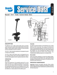
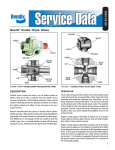
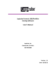
SD-03-3410
®
Bendix® VM-3™ Firewall Manifold
DESCRIPTION
NO.3
The VM-3™ is a control manifold serving as a manifold unit
for air passages between cab and engine compartment and
housing a double check valve and PR-4™ pressure protection
valve.
NO.9
NO.2
NO.4
NO.8
OPERATION
1. The double check valve receives supply air from the rear
(primary) supply system, through port No. 3 on Fig. 1,
and front (secondary) supply system, through port No.
1 on Fig. 1, and delivers whichever is higher in pressure
to the spring brake system and through another port to
the trailer supply through the dash mounted PP-7™ tractor
protection control valve.
2. The PR-4™ pressure protection valve receives supply air
from the front (secondary) supply port and supplies
protected air to three ports, one on the engine side and
two on the cab side. The PR-4™ valve will deliver air to
these ports only after the front supply system has built
up to at least 60 psi.
NO.1
NO.7
WARNING! PLEASE READ AND FOLLOW
THESE INSTRUCTIONS TO AVOID
PERSONAL INJURY OR DEATH:
3.
4.
5.
When working on or around a vehicle, the following
general precautions should be observed at all times.
1. Park the vehicle on a level surface, apply the
parking brakes, and always block the wheels.
Always wear safety glasses.
2. Stop the engine and remove ignition key when
working under or around the vehicle. When
working in the engine compartment, the engine
should be shut off and the ignition key should be
NO.5
FIGURE 1 - ENGINE SIDE
3. Supply air for the trailer control hand valve is taken from
a port inside the cab supplied from the rear (primary) air
supply.
The location and function of the various ports are shown in
Fig. 1 for the engine side of the VM-3™ manifold and in Fig.
2 for the cab side. The chart shown on Fig. 1 explains the
purpose and function of each port on the engine side and
the chart shown on Fig. 2 the cab side.
NO.6
6.
7.
removed. Where circumstances require that the
engine be in operation, EXTREME CAUTION should
be used to prevent personal injury resulting from
contact with moving, rotating, leaking, heated or
electrically charged components.
Do not attempt to install, remove, disassemble or
assemble a component until you have read and
thoroughly understand the recommended
procedures. Use only the proper tools and observe
all precautions pertaining to use of those tools.
If the work is being performed on the vehicle’s air
brake system, or any auxiliary pressurized air
systems, make certain to drain the air pressure from
all reservoirs before beginning ANY work on the
vehicle. If the vehicle is equipped with an AD-IS™
air dryer system or a dryer reservoir module, be
sure to drain the purge reservoir.
Following
the
vehicle
manufacturer’s
recommended procedures, deactivate the electrical
system in a manner that safely removes all
electrical power from the vehicle.
Never exceed manufacturer’s recommended
pressures.
Never connect or disconnect a hose or line
containing pressure; it may whip. Never remove a
component or plug unless you are certain all
system pressure has been depleted.
1
1
NO.3
2
3
4
NO.9
5
NO.2
NO.4
NO.8
6
7
10
11
8
NO.1
NO.7
9
NO.6
NO.5
ENGINE SIDE FIGURE 1
Port
No.
1
2
3
4
5
Diff. Lock
Blk.
6
Trl. Sup.
Yel.
7
(None)
8
2
Ident. on
Casting
Frt. Sup.
Blue
Park Sup.
Red
Rear Sup.
Green
Rad. Fan
Blk.
Air Rest.
Blk.
9
Prk. Del.
Red
10
Spg. Brk.
Rest. - Grn.
12
Function
Supply from No. 2 circuit reservoir.
Delivers air from double check valve
area to spring brake relay valve (R-8).
Supply from No. 1 circuit reservoir.
CAB BULKHEAD SIDE FIGURE 2
Port
No.
1
2
3
4
Delivers protected air supply from
PR-4 valve. Suggested use - air
operated fan clutch.
Connects directly to port No. 9 (Fig.
2) in cab. Suggested use - manifold
connection to differential lockout
mechanism. This is a 900 pass-through
passage.
Connects directly to port No. 10 in
cab. Suggested use - deliver air from
trailer supply valve (such as BW PP-7)
to trailer. This is a 90° pass-through
passage.
Connects directly to port No. 11 in
cab. Suggested use - any auxiliary
manifold function. This is a straight
through passage.
Connects directly to port No. 12 in
cab. Suggested use - air cleaner
restriction gauge. This is a straight
through passage.
Connects directly to port No. 8 (Fig.
2) in cab. Suggested use - deliver air
from park control valve to spring
brake control valve (SR-1™ valve).
This is a straight-through passage.
Connects to secondary circuit reservoir
and to port No. 4 (Fig. 2) in cab.
Suggested use - supplies secondary
reservoir air to the balance port of the
SR-1 spring brake control valve.
5
6
7
Ident. on
Casting
Frt. Gauge
Blue
Prk. Sup.
Red
Rear Gauge
Green
Hand Brake
Supply
Green
Access
Blk.
Access
Blk.
Trl. Sup.
Red
8
Prk. Del.
Red
9
Diff. Lock
10
Trl. Del.
11
(None)
12
Air Rest.
Blk.
Function
Connects to gauge for No. 2 circuit
reservoir.
Supplies air from double check valve
to park control valve.
Connects to gauge for No. 1 circuit
reservoir.
Supplies air from No. 2 circuit reservoir
to trailer hand control valve in
cab. Connects with No. 10 on engine
side.
Supplies protected air from PR-4™ valve
to any accessory control in cab.
Supplies protected air from PR-4™ valve
to any accessory control in cab.
Supplies air from double check valve
to trailer supply valve (tractor
protection).
Receives air from delivery of park
control valve to deliver to SR-1™ spring
brake control valve. Connects with No.
9 on engine side.
Receives air from delivery of differential lockout control valve. Connects
with No. 5 on engine side.
Receives air from trailer supply valve
(tractor protection) to supply trailer.
Connects to No. 6 on engine side.
Auxiliary manifold for any accessory
function connects to No. 7 on engine
side.
Suggested use - air cleaner restriction
gauge. Connects with No. 8 on engine
side.
3
4
1
3
2
FIGURE 3
FIGURE 4
8. Use only genuine Bendix ® replacement parts,
components and kits. Replacement hardware,
tubing, hose, fittings, etc. must be of equivalent
size, type and strength as original equipment and
be designed specifically for such applications and
systems.
9. Components with stripped threads or damaged
parts should be replaced rather than repaired. Do
not attempt repairs requiring machining or welding
unless specifically stated and approved by the
vehicle and component manufacturer.
10. Prior to returning the vehicle to service, make
certain all components and systems are restored to
their proper operating condition.
SERVICE CHECKS
PREVENTIVE MAINTENANCE
Important: Review the Bendix Warranty Policy before
performing any intrusive maintenance procedures. A warranty
may be voided if intrusive maintenance is performed during
the warranty period.
No two vehicles operate under identical conditions, as a
result, maintenance intervals may vary. Experience is a
valuable guide in determining the best maintenance interval
for air brake system components. At a minimum, the VM-3™
manifold should be inspected every year or 3600 operating
hours, whichever comes first, for proper operation. Should
the VM-3™ manifold not meet the elements of the operational
tests noted in this document, further investigation and service
of the valve may be required.
OPERATING AND LEAKAGE CHECKS
1. Start engine and charge both sides of dual system.
2. Stop engine, drain the front brake reservoir and disconnect
tube fitting at port No. 1 in Fig. 1, identified as Frt.
Sup. - Blue. Excessive leakage would indicate a faulty
double check valve.
3. Restore and recharge both systems. Drain the rear brake
reservoir and disconnect the fitting at port No. 3 in Fig.
1, identified as Rear Sup. - Grn. Excessive leakage would
indicate a faulty double check valve.
4. After closing the drain cock and restoring the plumbing
for the front reservoir remove the fitting at port No. 4 in
Fig. 1. Start the engine and observe front dash gauge.
Stop the engine when the gauge shows 40 psi. Excessive
leakage from port No. 4 would indicate a faulty PR-4™
valve. Restart engine and observe front gauge. Air should
start to blow from port No. 4 at 60-75 psi, indicating
PR-4™ valve is operating correctly. With engine shut off,
PR-4™ valve should close and retain at least 60 psi in
front reservoir.
If the VM-3™ manifold does not function as described above
or leakage is excessive, it is recommended that it be returned
to the nearest Bendix authorized distributor for an exchange
or a replacement unit. If this is not possible, the unit can be
repaired with genuine Bendix parts in which case the following
should prove helpful. A field maintenance kit is available under
pc. no. 289062.
3
DISASSEMBLY
ASSEMBLY
Block the wheels and drain the air brake system. Remove
air lines and remove manifold from vehicle.
Before assembly, lubricate all o-rings, bores and mating
surfaces with BW-650M lubricant pc. no. 291126 (Dow
Corning 55M). Replace any worn or deteriorated o-rings and
shuttle, item 2 in Fig. 5, if necessary.
Remove the large cap nut at port No. 1 and remove the
double check shuttle.
Remove the four machine screws from the PR-4™ valve cover.
(Caution - the cover is spring loaded.) Remove the PR-4™
valve piston assembly. Do not attempt to remove the retaining
ring and stem from the piston.
Install shuttle in guide in body and install cap nut
After cleaning and lubricating, assemble the PR-4™ valve
section, replacing o-ring item 3 and inlet exhaust valve item
4 in Fig. 6 as required.
Replace valve on vehicle and check per operating and
leakage tests.
BW1576 © 2004 Bendix Commercial Vehicle Systems LLC. All rights reserved. 4/2004 Printed in U.S.A.
4