1
NOTE: The valve is correctly modulating the brake
application.
2. Install shims (11 ) and graduating spring (12).
If the valve does not function as described, or if leakage is
excessive, it is recommended that it be replaced with a new
or remanufactured unit or repaired with genuine Bendix parts
available at Bendix outlets.
4. Install piston return spring (14) on piston; holding this
assembly vertical, place the body over the top of the
piston assembly, then turn over letting the assembly fall
into place.
REMOVING AND INSTALLING
5. Install the torsion spring (8) over the lever (7) noting that
parts are in correct relation to body as previously marked.
REMOVING
Block and hold vehicle by means other than air brakes.
Drain all air brake system reservoirs.
Identify air lines to TC-4™ valve to facilitate installation;
disconnect lines.
Remove mounting screws, then valve.
3. Install piston (13) on plunger (10).
6. Place the ends of the torsion spring (8) in holes in the
body. Install pin (9) and center in place.
7. Check for correct handle assembly by noting the torsion
spring and handle assembly will move the piston past
the inlet seat surface. (This can be seen by looking at
the supply port end of the valve.) If handle is not
assembled into body correctly, reassemble.
8. Install inlet valve (4) and inlet valve spring (3).
INSTALLING
Clean air lines to valve.
Mount valve securely with two mounting screws.
Identify and connect air lines to valve.
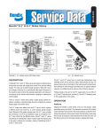
DISASSEMBLY (Refer to Figure 3)
9. Install sealing ring (2) on cap nut (1); install cap nut
(Torque to 50-100 inch pounds.)
10. Install disc (6) in locking button (5) and install button
into valve.
11. Test valve as outlined in “Operating and Leakage Test”
section.
1. Remove cap nut (1) and cap nut sealing ring (2).
2. Remove inlet valve spring (3) and inlet valve (4).
3. Remove locking button (5) and rubber friction disc (6).
4. Mark lever (7) in relation to body and torsion spring (8) in
relation to handle so that proper position can be
determined during assembly.
5. Using a small drift, carefully remove pin (9), lever (7) and
spring (8).
6. Remove plunger (10), shims (11) (if present), graduating
spring (12), piston (13) and piston return spring (14).
7. Remove o-rings (15 and 16) from plunger (10) and piston
(13).
CLEANING AND INSPECTION
Wash all metal parts in mineral spirits. Wipe all rubber parts
dry.
Inspect all parts for signs of wear or deterioration; check
springs for cracks, corrosion or distortion. Inspect piston
and inlet and exhaust seat for nicks or burrs.
It is recommended that all rubber parts and any other part
showing signs of wear or deterioration be replaced.
ASSEMBLY
Prior to assembly, lubricate the piston, o-rings and body
bores with Dow Corning 55-M pneumatic grease (Bendix
Pc. No. 291126).
1. Install o-rings (15 & 16) on plunger (10) and piston (13).
WARNING! PLEASE READ AND FOLLOW
THESE INSTRUCTIONS TO AVOID
PERSONAL INJURY OR DEATH:
When working on or around a vehicle, the following
general precautions should be observed at all times.
1. Park the vehicle on a level surface, apply the
parking brakes, and always block the wheels.
Always wear safety glasses.
2. Stop the engine and remove ignition key when
working under or around the vehicle. When
working in the engine compartment, the engine
should be shut off and the ignition key should be
removed. Where circumstances require that the
engine be in operation, EXTREME CAUTION should
be used to prevent personal injury resulting from
contact with moving, rotating, leaking, heated or
electrically charged components.
3. Do not attempt to install, remove, disassemble or
assemble a component until you have read and
thoroughly understand the recommended
procedures. Use only the proper tools and observe
all precautions pertaining to use of those tools.
4. If the work is being performed on the vehicle’s air
brake system, or any auxiliary pressurized air
systems, make certain to drain the air pressure from
all reservoirs before beginning ANY work on the
vehicle. If the vehicle is equipped with an AD-IS™
air dryer system or a dryer reservoir module, be
sure to drain the purge reservoir.