1
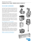
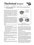
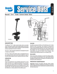
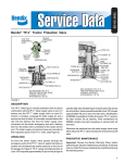
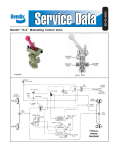
SD-03-824
®
Bendix® TC-7™ Trailer Control Brake Valve
19 O-RING
BRACKET
5 CAM FOLLOWER
LOCKWASHER
3
(SPECIAL)
18 O-RING
2 RETAINING RING
HANDLE
6 ADJUSTING RING
4 ADJUSTING RING
VALVE
FRICTION
WASHER 17
ADAPTER
7 CAM
SEALING 15
RING
8 GRADUATING SPRING
EXTERIOR VIEW
14 SCREW
9 PISTON
EXHAUST VALVE
10 O-RING
BODY
1
16
11 SPRING
HANDLE
12 INLET SEAT
INLET
VALVE
PARTIAL VIEW
(VALVE & HANDLE)
13 O-RING
FIGURE 1
S Y S T E M TRAILER TRACTOR
PARK
PARK
PARK
TRUCK/TRACTOR SYSTEM
TRACTOR
PARK
BRAKE
CHAMBERS
DS-2
DOUBLE CHECK
STOPLIGHT SWITCH
DC-4
PP-8
PP-1 OPTIONAL
SYSTEM T.M.C.
PARK TRACTOR
PARK
LQ-4
RATIO VALVE
TP-3 TRACTOR PROTECTION
SUPPLY LINE
SUPPLY LINE
SR-1 SPRING
BRAKE VALVE
E-7
TRAILER
CONTROL VALVE
DC-4
DOUBLE
CHECK
VALVE
AIR
DRYER
GAUGE
LP-3
ANTICOMPOUND
LINE
R-12 RELAY
VALVE
FRONT AXLE
SERVICE
RESERVOIR
ST-3
SAFETY
VALVE
SUPPLY
RESERVOIR
LP-3 LOW
PRESSURE
INDICATOR
CHECK
VALVE
D-2 GOVERNOR
COMPRESSOR
R-8 RELAY
VALVE
REAR AXLE
SERVICE
RESERVOIR
GAUGE
SPRING
BRAKES
FIGURE 2 - TYPICAL PIPING DIAGRAM
DESCRIPTION
The TC-7™ trailer control brake valve is a hand operated control
valve that provides graduated control of service brake air
pressure. The most common vehicle application is the
independent control of the trailer’s service brakes on a tractor
trailer combination.
Typically, the TC-7™ valve is mounted either inside the
steering column or clamped to the exterior of the column.
The three basic components of the TC-7™ valve are available
separately (valve, handle, bracket) to accommodate the
appropriate mounting configuration.
1
Because of its use as a trailer service brake control valve,
the TC-7™ valve should NOT be used in lieu of the vehicle
parking brakes. The handle is marked NOT FOR PARKING.
In general the TC-7™ valve should not be in use and left
unattended.
OPERATION
APPLYING
When the handle or actuating lever is moved in a clockwise
direction from the released position, force is exerted on the
pressure graduating spring through the action of the cam
and cam follower. The force of the spring on the piston causes
it to move down.
The exhaust seat, which is in the center of the piston,
contacts the exhaust valve and closes the exhaust passage
in the piston. The continued downward movement of the
piston moves the inlet valve-off its seat. Reservoir air
pressure flows by the open inlet valve and out the delivery
port.
HOLDING
The air pressure that flows by the open inlet valve also
becomes effective on the bottom area of the piston. As the
force of the air pressure beneath the piston balances the
force of the depressed graduating spring above, the piston
lifts slightly and the inlet valve returns to its seat. The exhaust
valve remains seated so the flow of air through the valve is
stopped and air pressure in the service line is held.
RELEASING
When the handle or operating lever is moved in a
counterclockwise direction the force above the piston is
decreased. The air pressure beneath will then lift the piston,
moving it away from the exhaust valve. With the exhaust
passage open, air pressure in the service line will exhaust
out the exhaust port of the valve.
PREVENTIVE MAINTENANCE
Important: Review the warranty policy before performing
any intrusive maintenance procedures. An extended warranty
may be voided if intrusive maintenance is performed during
this period.
Because no two vehicles operate under identical conditions,
maintenance and maintenance intervals will vary. Experience
is a valuable guide in determining the best maintenance
interval for any one particular operation.
Visually check for physical damage to the brake valve such
as broken air lines and broken or missing parts.
Every 3 months, 25,000 miles (40,000 km.) or 900 operating
hours perform Operating and Leakage Tests.
2
SERVICE CHECKS
OPERATING TEST
Park the vehicle on a level surface and block the wheels.
Connect an accurate test gauge to the delivery port of the
TC-7™ valve or connect the gauge to the service hose
coupling of the tractor. When the gauge is connected to the
service hose coupling, install a dummy hose coupling on
the supply (emergency) hose coupling and place the tractor
protection control in the trailer charging position. When the
TC-7™ valve handle is moved to the fully applied position,
the gauge should register full reservoir pressure.
NOTE: Some valves may be preset to deliver lower than
reservoir pressure; however, the standard valves
generally used on tractors are set to deliver full
reservoir pressure. Intermediate positions should
deliver proportional intermediate pressures. Upon
release, the gauge should immediately register zero.
LEAKAGE TEST
Locate the exhaust port or exhaust line and apply a soap
solution. (It is common practice to connect a line from the
valve exhaust port to a location remote from the immediate
driver’s area.) With the valve in the released position, exhaust
leakage should not exceed a 1" bubble in 5 seconds (100
sccm).
With the valve fully applied, leakage at the exhaust should
not exceed a 1" bubble in 3 seconds (175 sccm).
If the valve does not function as described or leakage is
excessive, it is recommended that it be replaced with a new
or remanufactured unit, or repaired with genuine parts
available at Bendix outlets.
REMOVAL & INSTALLATION
The removal, disassembly, assembly and installation
procedures are number keyed to the sectional and exterior
views of the TC-7™ valve in Figure 1.
REMOVAL
1. Block the wheels or hold the vehicle on a level surface
by means other than air brakes.
2. Drain all air pressure from all reservoirs.
3. Identify the air lines and connections and remove from
the TC-7™ valve.
4. Consult the vehicle manual for instructions on
disassembly of the steering column components.
NOTE: Some TC-7™ valve installations will be on the exterior
of the steering column, in which case Step 4 can
be disregarded.
5. Remove the TC-7™ valve handle(16) by first removing the
flat head Phillips machine screw(14) from the center of
the head/handle assembly.
6. Install rubber sealing ring(15) on cam follower(5).
6. Dismount the TC-7™ valve from the steering column.
8. Install cam follower(5) in body.
DISASSEMBLY
The following assembly and disassembly instructions are
written for the use of a Bendix Maintenance Kit 102145.
NOTE: Stop “ear” on cam follower will not permit improper
assembly of cam follower; however, make certain
that the positioning “ear” of the friction washer fits
in the wide slot in the body.
If the valve is disassembled in a vise, be sure that the vise is
not overtightened as the body and internal parts will distort.
9. Install o-ring(18) in adjusting ring adapter(4) and install
o-ring(19) in adjusting ring(6).
1. Remove and discard the adjusting ring lockwasher(3).
2. Remove and retain adjusting ring(6).
10. Install adjusting ring(6) in adapter(4) until adjusting ring
is flush with the underside of the adapter.
NOTE: A spanner wrench can be used to rotate the adjusting
ring, but if such a wrench is not available, the
adjusting ring can be returned with a small
screwdriver inserted in one of the inner notches of
the ring.
NOTE: There are two indexing lugs on the adapter that fit
into slots in the valve body when the adapter is
installed. Be sure to install the adjusting ring with
its wrench slots accessible (up) after the valve is
assembled.
3. Remove and discard retaining ring(2).
11. Position the adapter(4) and adjusting ring(6) assembly
over the cam follower(5), making certain the adapter lugs
fit into the body slots.
4. Remove adjusting ring adapter(4), cam follower(5), sealing
ring(15) and friction washer(17). Discard sealing ring(15)
and o-rings (18 & 19). Retain all other parts.
NOTE: Note whether friction washer is installed with ribs
against or away from sealing ring. Must be installed
same-way during assembly.
7. Install the friction washer(17) on cam follower(5) in same
manner as noted in Step 4 of Disassembly.
12. Push down on cam follower(5) and install snap ring(2).
Be certain the snap ring is completely seated in its
groove.
5. Remove and retain cam(7) and graduating spring(8).
NOTE: If lugs on adapter(4) are not in their body slots, the
snap ring cannot be installed completely.
6. Remove and retain piston(9). Remove and discard
o-ring(10) from piston(9).
13. Before installing the lockwasher(3), adjust the valve as
described.
7. Remove and discard piston return spring(11).
ADJUSTMENT
8. Using an 11/16" deep well socket wrench, remove and
discard inlet and exhaust valve assembly(12) and
o-ring(13).
Generally, the TC-7™ brake valve should deliver full reservoir
pressure; however, there are a few exceptions in special
applications.
ASSEMBLY
1. If the delivered pressure is below specified final delivery
pressure, it can be adjusted by removing the head and
adjusting ring lockwasher and rotating the adjusting ring
clockwise to raise the delivery pressure.
Prior to assembly, wash parts retained during disassembly
in mineral spirits and dry thoroughly. Using Bendix lubricant
291126 or a silicone lubricant equivalent to Dow Corning
55-M, lubricate the body bores, cam, cam follower and all
o-rings and o-ring grooves. NOTE: Do not lubricate sealing
ring, friction washer or cam follower serrations.
1. Install o-ring(13) on inlet and exhaust valve assembly(12)
and using an 11/16" deep well socket wrench, install
inlet and exhaust valve assembly(12). Torque to 15 inch
pounds.
2. Install piston return spring(11).
3. Install o-ring(10) on piston(9) and install piston(9) in
body(1).
4. Install graduating spring(8) in body(1).
Care should be taken not to raise the delivery pressure
beyond the design limits; exhaust opening could be
restricted.
2. If the delivery pressure is above specified final delivery
pressure, it can be lowered by rotating the adjusting
ring counter-clockwise.
NOTE: A spanner wrench can be used to rotate the adjusting
ring, but if such a wrench is not available, the
adjusting ring can be turned with a small screwdriver
inserted in one of the inner notches of the ring.
3. After adjustment is complete, install lockwasher(3) to
hold the adjustment.
5. Install cam(7) in body(1) with flat side toward graduating
spring. Index cam “ears” to corresponding slots in body.
3
INSTALLATION
1. Using the identification made during removal, reconnect
the air lines to the TC-7™ valve. NOTE: Maximum torque
for fittings is 10 ft. lbs.
2. Consult the vehicle manual for instructions on remounting
the TC-7™ valve in or on the steering column. Do not
overtorque the three 1/4-20 mounting screws. (30-60 inch
pounds) (3.39-6.77 kPa)
3. Remount the TC-7™ valve handle(16) on the hex cam
follower(5) and secure flat head screw(14). Torque to
30-60 inch pounds. (3.39-6.77 kPa)
NOTE: Handle position cannot be adjusted.
WARNING! PLEASE READ AND FOLLOW
THESE INSTRUCTIONS TO AVOID
PERSONAL INJURY OR DEATH:
When working on or around a vehicle, the following
general precautions should be observed at all times.
1. Park the vehicle on a level surface, apply the
parking brakes, and always block the wheels.
Always wear safety glasses.
2. Stop the engine and remove ignition key when
working under or around the vehicle. When
working in the engine compartment, the engine
should be shut off and the ignition key should be
removed. Where circumstances require that the
engine be in operation, EXTREME CAUTION should
be used to prevent personal injury resulting from
contact with moving, rotating, leaking, heated or
electrically charged components.
4
3. Do not attempt to install, remove, disassemble or
assemble a component until you have read and
thoroughly understand the recommended
procedures. Use only the proper tools and observe
all precautions pertaining to use of those tools.
4. If the work is being performed on the vehicle’s air
brake system, or any auxiliary pressurized air
systems, make certain to drain the air pressure from
all reservoirs before beginning ANY work on the
vehicle. If the vehicle is equipped with an AD-IS™
air dryer system or a dryer reservoir module, be
sure to drain the purge reservoir.
5. Following
the
vehicle
manufacturer’s
recommended procedures, deactivate the electrical
system in a manner that safely removes all
electrical power from the vehicle.
6. Never exceed manufacturer’s recommended
pressures.
7. Never connect or disconnect a hose or line
containing pressure; it may whip. Never remove a
component or plug unless you are certain all
system pressure has been depleted.
8. Use only genuine Bendix ® replacement parts,
components and kits. Replacement hardware,
tubing, hose, fittings, etc. must be of equivalent
size, type and strength as original equipment and
be designed specifically for such applications and
systems.
9. Components with stripped threads or damaged
parts should be replaced rather than repaired. Do
not attempt repairs requiring machining or welding
unless specifically stated and approved by the
vehicle and component manufacturer.
10. Prior to returning the vehicle to service, make
certain all components and systems are restored
to their proper operating condition.
BW1568 © 2004 Bendix Commercial Vehicle Systems LLC. All rights reserved. 3/2004 Printed in U.S.A.